TSerie - Electric bike Flyer - Free user manual and instructions
Find the device manual for free TSerie Flyer in PDF.
User questions about TSerie Flyer
0 question about this device. Answer the ones you know or ask your own.
Ask a new question about this device
Download the instructions for your Electric bike in PDF format for free! Find your manual TSerie - Flyer and take your electronic device back in hand. On this page are published all the documents necessary for the use of your device. TSerie by Flyer.
USER MANUAL TSerie Flyer
natural_image
Side profile of a modern bicycle with visible front wheel, rear seat, and front basket (no text or symbols)FLYER Tour/Urban

17 Knopfzellen-Fach
natural_image
Two-step diagram showing hand positioning of a vehicle seatbelt mechanism, no text or symbols present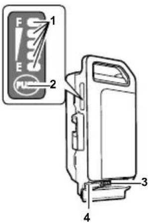
Akku laden
natural_image
Abstract geometric pattern with star-like shapes and shaded rectangular blocks (no text or symbols)natural_image
Line drawing of a hand adjusting a mechanical component with a black arrow indicating rotation (no text or symbols)
natural_image
Illustration showing a hand holding a bicycle with a cable, and a close-up of the foot using a bicycle pedal (no text or symbols present)
natural_image
Pure mechanical cross-section diagram without any text, numbers, or symbols
natural_image
Mechanical linkage diagram showing a lever mechanism with directional arrows and safety symbols (no readable text or labels)natural_image
Three diagrams showing different clamp or clamping techniques (no text or symbols present)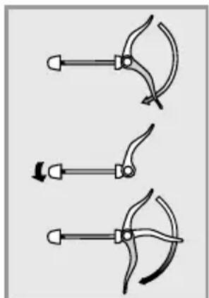
natural_image
Three diagrams showing a tool with curved blades and arrows indicating motion (no text or symbols)natural_image
Close-up of a bicycle wheel assembly with two circular warning symbols (X and Y) placed on it, no readable text or labels present.natural_image
Close-up of a hand adjusting a bicycle wheel rim, with an arrow pointing to the component (no text or symbols visible)natural_image
Close-up of hands adjusting a mechanical component with directional arrows and a plus sign (no readable text or symbols)natural_image
Close-up of a bicycle wheel assembly with a white component and a directional arrow indicating rotation (no text or symbols)Ausbau
natural_image
Close-up of a bicycle wheel with a hand adjusting a component, showing a curved arrow indicating rotation (no text or symbols present)natural_image
Close-up of a hand adjusting a mechanical component with a white arrow pointing to it (no visible text or symbols)natural_image
Close-up of a hand adjusting a mechanical component with an arrow indicating rotational motion (no text or symbols visible)natural_image
Close-up of a hand adjusting a bicycle wheel component with a black arrow pointing to the handle (no text or symbols visible)natural_image
Silhouette of a person riding a bicycle with 90-degree angle annotations (no text or symbols on the diagram itself)natural_image
Mechanical assembly diagram showing a lever mechanism with no visible text or symbolsnatural_image
Illustration of a hand holding a tool with a labeled arrow indicating direction (no text or symbols present)natural_image
Illustration of a hand using a mechanical tool to adjust or install a component, with no visible text or symbols.natural_image
Illustration of hands performing a medical procedure with a tool, no text or symbols presentnatural_image
Illustration of a robotic arm with a curved tool and labeled step 4 (no text or symbols on the diagram itself)
natural_image
Technical line drawing of a mechanical assembly (no text or symbols)natural_image
Diagram of a manual tool with lever and handle, showing motion trajectory (no text or symbols)natural_image
Diagram of a bicycle steering wheel with lever mechanism (no text or labels)natural_image
3D illustration of a cylindrical mechanical component labeled 'Autoventil' (no other text or symbols)natural_image
Diagram of a bicycle wheel with two vertical guide rails, no text or symbols presentDE

natural_image
Mechanical gear mechanism diagram showing interlocking gears and linkages (no text or symbols)natural_image
Mechanical gear mechanism diagram showing interlocking gears and chains (no text or symbols)natural_image
Mechanical gear mechanism diagram showing chain and gear components (no text or symbols)Quelle: Shimano ^® techdocs

natural_image
Diagram of a manual tool with lever and handle, showing motion lines (no text or symbols)Rücktrittbremse
natural_image
Pure technical line drawing of a curved metal profile (no text or symbols)natural_image
Pure technical line drawing of a curved mechanical component (no text or symbols)verschlissene Felge
natural_image
Line drawing of a bicycle brake lever system (no text or symbols)neue Bremsgummis
natural_image
Line drawing of two bicycle levers with attached clips (no text or symbols)natural_image
Mechanical assembly diagram showing two clamps and a bracket (no text or symbols)natural_image
Illustration of hands using a tool to adjust or install a component, no text or symbols visibleAkku entnehmen
natural_image
Mechanical linkage diagram showing a lever and chain assembly (no text or symbols)natural_image
Diagram showing a hand operating a car wheel with a faucet, no text or symbols present
natural_image
Diagram showing a mechanical linkage or wheel assembly before and after division (no text or symbols present)natural_image
Three types of clamping tools with different grip configurations (no text or symbols)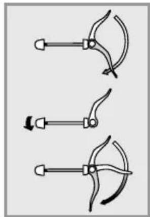
natural_image
Three diagrams showing a hand tool with curved blades and a handle, no text or symbols presentFaltgelenks: 10kg/98,1N

natural_image
Mechanical assembly diagram showing a lever mechanism with no visible text or symbolsnatural_image
Illustration of a robotic arm with a numbered label (1) indicating a step, showing motion and movement without any text or symbols.natural_image
Illustration of a hand using a tool to adjust or install a mechanical component, with no visible text or symbols.natural_image
Diagram showing a person interacting with a device, possibly a robotic or mechanical system (no text or symbols present)natural_image
Line drawing of a bicycle with front wheel, rear wheels, and side-mounted sensors (no text or symbols)natural_image
Illustration of a person climbing a rope with a downward arrow, no text or symbols presentnatural_image
Diagram of a mechanical component with an arrow indicating direction, no text or symbols present
natural_image
Diagram of hands performing a mechanical or electrical procedure with no visible text or symbolsnatural_image
Mechanical assembly diagram showing a lever mechanism with a numbered label (1) indicating a step or component, no text or symbols present.


natural_image
Two-step diagram showing hand positioning of a vehicle seatbelt mechanism, with no text or symbols present.natural_image
Abstract pattern of star-shaped shapes with rounded corners and a central gray rectangle (no text or symbols)natural_image
Line drawing of a hand adjusting a mechanical component with a black arrow indicating rotation (no text or symbols)
natural_image
Illustration showing a hand using a tool to lift a bicycle, and the foot wearing a seatbelt (no text or symbols present)
natural_image
Pure mechanical component diagram without any text, numbers, or symbols
natural_image
Mechanical linkage diagram showing lever mechanism and safety symbols (no text labels)natural_image
Three diagrams showing different types of clamp or tool configurations (no text or symbols present)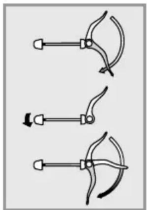
natural_image
Three hand-painted diagrams showing mechanical clamping or tool positioning (no text or symbols)natural_image
Close-up of a bicycle wheel assembly with two circular button symbols (X and ✓) highlighted in black, no readable text or labels present.natural_image
Close-up of hands using a bicycle wheel to adjust the wheel rim (no text or symbols visible)natural_image
Close-up of a hand adjusting a mechanical component with an arrow indicating rotation (no text or symbols visible)natural_image
Close-up of a bicycle wheel assembly with a white component and a curved arrow indicating rotation (no text or symbols)Démontage
natural_image
Close-up of a bicycle wheel assembly with a hand adjusting a component, showing no text or symbols.natural_image
Close-up of hands adjusting a mechanical component with a white arrow pointing to the part (no visible text or symbols)natural_image
Close-up of a hand adjusting a mechanical component with an arrow indicating rotational motion (no text or symbols visible)4. Retirez l'axe
natural_image
Close-up of a hand adjusting a bicycle wheel component with a tool (no visible text or symbols)11.2 Réglage de la position assise
natural_image
Mechanical assembly diagram showing a lever mechanism with a handle and lever (no text or symbols)natural_image
Illustration of a hand holding a tool with a directional arrow, no text or symbols presentnatural_image
Mechanical assembly diagram showing a hand operating a clamp or clamp device with a pointer indicating motion (no text or symbols present)natural_image
Illustration of hands performing a mechanical or electrical procedure with no visible text or symbolsnatural_image
Illustration of a robotic arm with a handle and lever, labeled with number 4 (no text or symbols on the diagram itself)
natural_image
Technical line drawing of a mechanical assembly (no text or symbols)Potence réglable
natural_image
Diagram of a mechanical lever mechanism with dashed lines indicating motion or force (no text or symbols)natural_image
Illustration of a hand using a manual tool to lift a bicycle wheel (no text or symbols)Source : Shimano® techdocs
natural_image
Technical illustration of a cylindrical mechanical component with threaded shaft and flange (no text or symbols)natural_image
Diagram of a bicycle wheel with two vertical guide rails (no text or labels)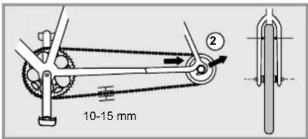


natural_image
Mechanical gear mechanism diagram showing pulleys and gears (no text or labels)natural_image
Mechanical gear mechanism diagram showing interlocking gears and chains (no text or symbols)natural_image
Mechanical gear mechanism diagram showing pulley, chain, and gear assembly (no text or symbols)Source : Shimano® techdocs

natural_image
Diagram of a manual tool with lever and handle, showing motion lines (no text or symbols)natural_image
Technical line drawing of a curved metal profile (no text or symbols)natural_image
Simple line drawing of a curved, segmented object with no text or symbolsJante usée
natural_image
Line drawing of a bicycle brake lever system (no text or symbols)natural_image
Line drawing of two bicycle brake clips with no text or symbolsnatural_image
Mechanical clamp assembly diagram showing two clamps and connecting wires (no text or labels)Source : Shimano ^® techdocs


Source : Shimano® techdocs
natural_image
Line drawing of hands using a tool to adjust or install a component, no text or symbols presentRetirez la batterie
natural_image
Mechanical linkage diagram showing a lever and chain assembly (no text or labels)natural_image
Diagram showing a hand holding a tool above a car wheel, with a faucet and tire in the background (no text or symbols)
natural_image
Diagram showing a mechanical linkage or wheel assembly before and after division (no text or symbols present)natural_image
Three diagrams showing different types of clamping or tool positions (no text or symbols present)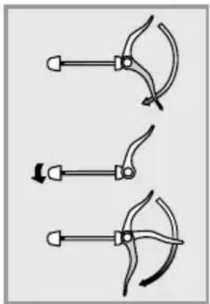
natural_image
Three diagrams showing a tool with curved blades and arrows indicating motion (no text or symbols)natural_image
Mechanical assembly diagram showing a lever mechanism with no visible text or symbolsnatural_image
Illustration of a robotic arm with a handle and lever, labeled with number 1 (no text or symbols on the diagram itself)natural_image
Illustration of a hand holding a mechanical component with a numbered label (2), no text or symbols present.natural_image
Diagram showing a person climbing a slope with an arrow and number 3, no readable text or symbols present.natural_image
Line drawing of a bicycle with front wheel, rear wheels, and side-mounted sensors (no text or symbols)natural_image
Illustration of a person climbing a rope with a downward arrow, no text or symbols presentnatural_image
Diagram of a mechanical component with directional arrows indicating movement or force (no text or symbols)
natural_image
Illustration of hands connecting a tool to a mechanical component, no text or symbols presentnatural_image
Mechanical assembly diagram showing a lever mechanism with a numbered label (1) indicating a step or component, no text or symbols present.


natural_image
Technical illustration showing two mechanical assembly steps with arrows indicating motion (no text or symbols)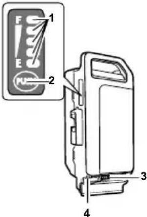
natural_image
Abstract pattern of star-shaped shapes with rounded corners and shaded inner rectangles (no text or symbols)natural_image
Line drawing of a hand adjusting a mechanical component with a black arrow indicating rotation (no text or symbols)
natural_image
Illustration showing a hand using a tool to lift a bicycle, and the foot wearing a seatbelt (no text or symbols present)
natural_image
Pure mechanical cross-section diagram without any text, numbers, or symbols
natural_image
Mechanical linkage diagram showing lever mechanism and safety symbols (no text labels)natural_image
Three diagrams showing different types of clamping or tool manipulation techniques (no text or symbols present)natural_image
Three hand tools with curved blades and arrows indicating motion (no text or symbols)natural_image
Close-up of a bicycle wheel assembly with two circular control buttons (X and ✓) highlighted, no readable text or symbols present.natural_image
Close-up of a hand adjusting a bicycle wheel rim, with a white arrow pointing to the rim (no text or symbols visible)natural_image
Close-up of hands adjusting a mechanical component with directional arrows and a plus sign (no readable text or symbols)natural_image
Close-up of a bicycle wheel assembly with a white component and black hub, showing a circular arrow indicating rotational motion (no text or symbols)Smontaggio
natural_image
Close-up of a bicycle wheel assembly with a hand adjusting the wheel (no visible text or symbols)- Premere la bussola fi no a far entrare la fl angia.
natural_image
Close-up of hands adjusting a mechanical component with a white arrow pointing to the part (no visible text or symbols)natural_image
Close-up of a hand adjusting a mechanical component with an arrow indicating rotational motion (no text or symbols visible)- Estrarre l'asse.
natural_image
Close-up of a hand adjusting a bicycle wheel component with a tool, no visible text or symbolsnatural_image
Silhouette of a person riding a bicycle with marked angles (90° and 90°) indicating bicycle lane markings.natural_image
Diagram of a robotic arm with motion arrows indicating movement (no text or symbols)natural_image
Illustration of a robotic arm with a labeled step (1), showing motion and movement without any text or symbols.natural_image
Illustration of a mechanical clamp or clamp mechanism with a hand operating it, no text or symbols presentnatural_image
Illustration of hands performing a medical procedure with a tool and arrow (no text or symbols)natural_image
Illustration of a robotic arm with a curved tool and labeled step 4 (no text or symbols on the diagram itself)
natural_image
Technical line drawing of a mechanical assembly with no visible text or symbolsnatural_image
Diagram of a manual tool with handle and lever mechanism, showing motion lines (no text or symbols)natural_image
Illustration of a hand using a manual tool to lift a bicycle wheel (no text or symbols)Fonte: Shimano® techdocs
natural_image
Diagram of a bicycle wheel with two vertical guide rails (no text or labels)

natural_image
Mechanical gear mechanism diagram showing interlocking gears and linkages (no text or symbols)natural_image
Mechanical gear mechanism diagram showing interlocking gears and chains (no text or symbols)natural_image
Mechanical gear mechanism diagram showing pulley, chain, and gear assembly (no text or symbols)Fonte: Shimano ^® techdocs

natural_image
Diagram of a manual tool with lever and handle, showing motion lines (no text or symbols)Freno a contropedale
natural_image
Pure technical line drawing of a curved mechanical component (no text or symbols)natural_image
Pure technical line drawing of a curved mechanical component (no text or symbols)Cerchio usurato
natural_image
Line drawing of a bicycle brake lever mechanism (no text or symbols)natural_image
Line drawing of a bicycle brake lever mechanism (no text or symbols)natural_image
Mechanical clamp assembly diagram showing two clamps and a handle (no text or labels)Fonte: Shimano® techdocs
Fonte: Shimano® techdocs
natural_image
Illustration of hands using a tool to adjust or install a component, no text or symbols visiblenatural_image
Mechanical linkage diagram showing a lever and chain assembly (no text or labels)natural_image
Diagram showing a mechanical component with a lever and gear, intersected by a diagonal line (no text or symbols)
natural_image
Diagram showing a mechanical linkage or wheel assembly before and after division (no text or symbols present)natural_image
Three diagrams showing mechanical clamping or turning mechanisms with arrows indicating direction (no text or symbols)natural_image
Three diagrams showing a hand tool with curved blades and arrows indicating motion (no text or symbols)natural_image
Line drawing of a bicycle with a person riding its side, no text or symbols present
natural_image
Mechanical assembly diagram showing a lever mechanism with a numbered component (no text or symbols present)natural_image
Illustration of a robotic arm with a numbered label (1) indicating a step, showing motion and movement without any text or symbols.natural_image
Illustration of a hand using a tool to adjust or install a mechanical component, with no visible text or symbols.natural_image
Diagram showing a mechanical assembly with an arrow and numbered label (3), no readable text or symbols present.natural_image
Line drawing of a bicycle with front wheel, rear wheels, and side-mounted sensors (no text or symbols)natural_image
Illustration of a person climbing a rope with a downward arrow indicating motion (no text or symbols)natural_image
Diagram of a mechanical component with an arrow indicating direction, no text or symbols present
natural_image
Illustration of hands connecting a tool to a mechanical component, no text or symbols presentnatural_image
Mechanical assembly diagram showing a lever mechanism with no visible text or symbols

Built with a Panasonic motor
Translation of the original instruction manual
The FLYER and its components
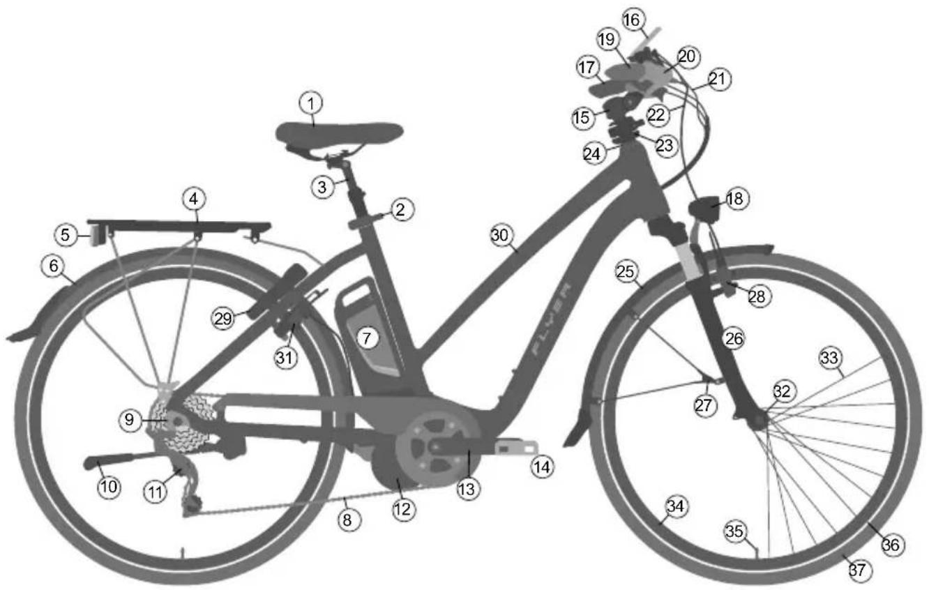
① Seat
② Seat post clamp with quick release
③ Seat post
④ Rack
⑤ Rear light with integrated rear reflector
⑥ Mudguard for the back tyre
⑦ Battery
⑧ Chain
⑨ Dropout
⑩ Side stand
⑪ Rear derailleur
⑫ Electrical motor
⑬ Crank arm
⑭ Pedal
⑮ Stem
⑯ Display
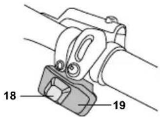
⑰ Handlebars with grip
18 Front headlight with reflector
⑲ Shifter
20 Brake lever
21 Shifter cable
22 Brake cable
23 Speedlifter Twist
⑳ Stem bearing or headset
25 Front mudguard
26 Suspension fork
27 Safety fixture mudguard
28 Front wheel brake
29 Frame lock
30 Frame
31 Rear wheel brake
Wheel
32 Front wheel hub
③3 Spoke
③4 Rim
35 Valve
36 Reflector stripes
③7 Tyres
Index
IMPORTANT:
You can find a current instruction manual here: flyer-bikes.com/manuals
- Foreword 134
- Definition of terms.... 134
- Safety information.... 134
- Safety instructions for all electrical systems ..... 136
- FLYER with Panasonic motor 137
5.1 Operation with central display 137
5.2 Operation with laterally mounted display ..... 138
5.3 Battery 139
5.4 Pushing aid 141
- Legal requirements ..... 141
- Intended use 142
- Before the first ride 142
- Before each ride 143
- After a fall.... 144
- Adjusting the bike to the rider ..... 145
11.1 Operating quick releases and axles..... 145
11.2 Setting up the seating position.... 148
11.3 Setting up the brake levers 150
11.4 Suspension elements.... 151
- Wheels and tyres 151
12.1 Checking the rims 151
12.2 Tyres and inner tubes 152
12.3 Dealing with a flat tyre 152
- Bicycle gears 154
- Bicycle chain and sprocket ..... 155
- Brake 157
- Lighting system.... 161
- Riding with additional load.... 161
-
Mudguard.... 162
-
Accessories and equipment.... 162
19.1 Transporting children/child seats 162
19.2 Bicycle trailers and child trailers.... 163
19.3 Roof and rear carrier on a car 163
- Bike folding instructions FLYER Pluto 165
20.1 Using quick releases 166
20.2 Adjusting and readjusting the frame's folding hinge .. 166
20.3 Folding instructions for the FLYER Pluto . . . . . . . . . 166
20.4 Unfolding the FLYER Pluto 168
- Electrical motor 170
- Wearing parts ..... 171
- Inspection plan 171
23.1 Maintenance work and exchange of wearing parts . . . 172
-
General warranty....173
-
Environmental protection tips 173
Declaration of conformity 218
Legal disclosure 218
1. Foreword
Dear FLYER customer
Thank you for choosing a FLYER. Enjoy your journey of discovery on your FLYER and have a safe ride.
Thank you for your trust in our product.
Your FLYER Team
2. Definition of terms
These original operating instructions contain the most important information required to familiarise yourself with your new FLYER, to get to know its technology, to attend to safety aspects and prevent damage to persons, goods and the environment. You should therefore keep this manual in a safe place, always have it to hand and observe the pointers provided in this manual which have proven to be helpful when using this FLYER. Please provide these instructions with the FLYER when you lend your FLYER to other persons. You are strongly advised to carefully read the attached instructions manual to the electric drive system before you use your bike for the first time. The following symbols are repeatedly shown on the pages below:

DANGER: There is a risk of personal injury.

NOTE: Here you can find important information which will help you get the most out of your FLYER e-bike.

WARNING: This is an indication of possible damage to property or the environment.

OBSERVE PRESCRIBED TORQUE:
Screw connections must be tightened with a specific fastening torque. This is only possible with a special tool called a torque spanner. Have this work performed by your FLYER specialist retailer if you do not have the right tools or specialised knowledge. Parts which have been fitted with the incorrect torque may break or fall off, which can lead to serious falls. The correct fastening torque is either imprinted on the component or listed in the “Fastening torques” chapter.
From now on, these symbols will be used without further explanation. However, they will always stand for the content and warning being mentioned. Carefully read all the instructions.
3. Safety information
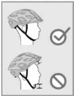
It is essential that you perform the tests and inspections stipulated. Negligence is a great danger, especially in this area. Protect yourself and other road traffic participants by behaving safely
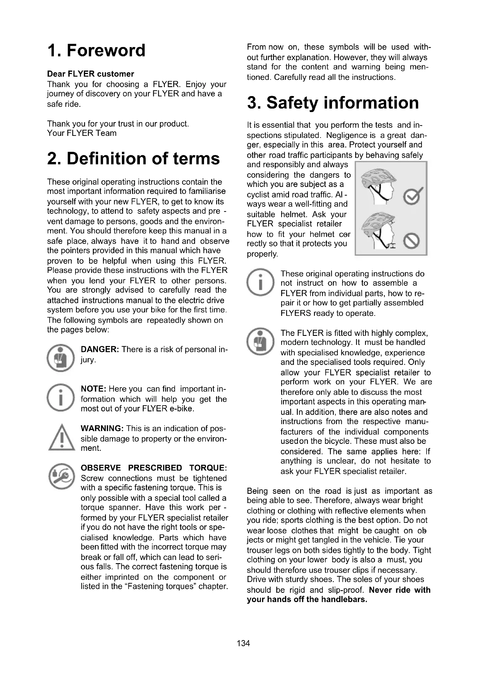
and responsibly and always considering the dangers to which you are subject as a cyclist amid road traffic. Always wear a well-fitting and suitable helmet. Ask your FLYER specialist retailer how to fit your helmet correctly so that it protects you properly.

These original operating instructions do not instruct on how to assemble a FLYER from individual parts, how to repair it or how to get partially assembled FLYERS ready to operate.

The FLYER is fitted with highly complex, modern technology. It must be handled with specialised knowledge, experience and the specialised tools required. Only allow your FLYER specialist retailer to perform work on your FLYER. We are therefore only able to discuss the most important aspects in this operating manual. In addition, there are also notes and instructions from the respective manufacturers of the individual components used on the bicycle. These must also be considered. The same applies here: If anything is unclear, do not hesitate to ask your FLYER specialist retailer.
Being seen on the road is just as important as being able to see. Therefore, always wear bright clothing or clothing with reflective elements when you ride; sports clothing is the best option. Do not wear loose clothes that might be caught on objects or might get tangled in the vehicle. Tie your trouser legs on both sides tightly to the body. Tight clothing on your lower body is also a must, you should therefore use trouser clips if necessary. Drive with sturdy shoes. The soles of your shoes should be rigid and slip-proof. Never ride with your hands off the handlebars.
Look ahead while riding and familiarise yourself with the response of the brakes in a safe and traffic-free area before your first drive.
Only one person may ride on the FLYER at a time. Do not carry any loose, unattached objects with you. Always remember to fold in the prop stand before riding off.
Check that the quick releases are fastened and secured each time your FLYER has been left unattended – even if it is for just a short time. Regularly make sure that all screws and parts are securely fastened.
Your responsibility as the owner of the vehicle includes the actions and the safety of possible under-age users as well as the technical state of the FLYER e-bike and its adaptation to the driver. Ensure that under-age drivers have learned safe and responsible handling of the e-bike - preferably in the environment in which they will ride it.

Minors may only ride a FLYER once they have reached the required age and hold the necessary driving license.
Important preparations for riding your FLYER
It is essential to read the operating instructions to familiarise yourself with your new FLYER. Please read all of the instructions to ensure safe use. This operating manual assumes that you and all other users of this FLYER e-bike have a basic knowledge of bicycles and e-bikes. Please contact your FLYER specialist retailer if you have any questions and for important maintenance tasks. All persons using, cleaning, maintaining, repairing and disposing of the FLYER must know and understand the content of these instructions.
Not observing this information may have considerable consequences for your safety. If something is out of place, it could cause severe accidents or you falling over – which could also lead to addition costs and repair.
Along with reading the specific instructions on how to use your FLYER, you need to inform yourself on the rules and regulations that are enforced on public roads – these can change from country to country.
Warnings and important information
- Please consider that additional support by the motor helps you drive at significantly higher speeds than you are used to with your bicycle.
-
Please note that the motor of your FLYER e-bike may get hot during long ascents. Do not touch. You could suffer burns.
-
The same applies to brake discs which can get very hot when braking. Avoid continuous use of the brakes while driving, even during extended or steep downhill rides.
- Never attempt to operate your FLYER with any battery other than the original battery. Your FLYER specialist retailer will advise you regarding the correct FLYER battery.
- Never remove component covers or parts. This could expose live parts. Connecting points could also be live. Maintenance work may only be performed by your FLYER specialist retail - er. Inappropriate work may lead to electrical shocks and injuries.
• Take care not to damage or crush cables while maintaining, cleaning, transporting or adjusting your FLYER. - If it is no longer possible to use the bike safely, you may no longer use your FLYER. This is the case when live parts or the battery are damaged or when you detect cracks in the frame or in components. The FLYER must be left unused and secured until it has been checked by a FLYER specialist retailer.
- You should be particularly careful if children have access to the bike. Prevent children from inserting objects into openings in the bike. They could suffer a life-threatening electric shock.
- To store your FLYER in an assembly stand, it should be attached by the seat post. High-quality aluminium frames may be damaged by the clamping force of the holder.
- The same applies to brake discs which can get very hot when braking. Avoid continuous use of the brakes while driving, even during extended or steep downhill rides.
- Never attempt to operate your FLYER with any battery other than the original battery. Your FLYER specialist retailer will advise you regarding the correct FLYER battery.
- Never remove component covers or parts. This could expose live parts. Connecting points could also be live. Maintenance work may only be performed by your FLYER specialist retail - er. Inappropriate work may lead to electrical shocks and injuries.
• Take care not to damage or crush cables while maintaining, cleaning, transporting or adjusting your FLYER. - If it is no longer possible to use the bike safely, you may no longer use your FLYER. This is the case when live parts or the battery are damaged or when you detect cracks in the frame or in components. The FLYER must be left unused and secured until it has been checked by a FLYER specialist retailer.
- You should be particularly careful if children have access to the bike. Prevent children from inserting objects into openings in the bike. They could suffer a life-threatening electric shock.
- To store your FLYER in an assembly stand, it should be attached by the seat post. High-quality aluminium frames may be damaged by the clamping force of the holder.
4. Safety instructions for all electrical systems
Read all the safety instructions and regulations.
Non-compliance with the safety instructions and regulations may lead to electric shock, fire and/or severe injuries.
Keep all safety instructions and regulations for future use.
The term “battery” in these operating instructions refers to all standard batteries.
Your FLYER is supplied with the corresponding operating manual for the integrated motor from the component manufacturer. You are strongly advised to carefully read the attached instructions manual to the electric drive system before you use your bike for the first time. You should also pay close attention to the safety guidelines.
Information concerning the FLYER e-bike's operation, maintenance, care and technical data can be found in this manual and online on the respective websites to the manufacturers' components.

Remove the battery from the e-bike before you begin working on the it (i.e. installation, maintenance, working on the chain). The same applies when storing the bike or transporting it on a car, train or airplane.
There is a risk of injury if the electrical system is unintentionally activated.

The electric drive system built into your FLYER e-bike is extremely powerful. Correct and safe operation requires you to have your FLYER regularly maintained by a specialist retailer. Immediately remove the battery when you notice damage to the electrical system, particularly when live parts are exposed after an accident. Always contact your FLYER specialist retailer when you require repairs, want to ask a question, have a problem or discover a defect. A lack of technical knowledge can lead to severe accidents, injuries or damage.

The FLYER was designed for driving with the motor. Never drive without a battery or with the system switched off, as no light will be available without the battery or system.

Your FLYER has an automatic protection against overheating. In the case of overheating, this protection will switch off the motor function until the motor has reached a non-critical temperature. The remaining functions are continued, e.g. you can still drive with the lights on.

When the bike is not in use, the system will automatically turn off together with the light function after 10 minutes. Therefore, always be sure to turn on the display before each ride.
5. FLYER with Panasonic motor
5.1 Operation with central display
Press the on/off button 13 on the display to activate the assistance function or the various indicators. When switching on the bike's system, you will automatically activate the [No Assist] modus.
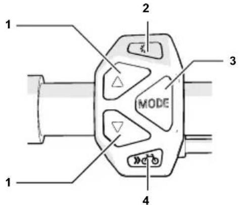
1 Selection key Assistance mode
Select the [HIGH], [AUTO], [STANDARD] or [ECO] assistance mode. Select [NO ASSIST] to deactivate the assistance function. You can now ride your FLYER just like you would a normal bicycle by pedalling. The rest of the functions, including the operation elements' display, will remain unchanged. In the assistance mode [AUTO], the system will automatically and independently select the support level best suitable for the current riding situation.
The selected assistance function of the motor switches on as soon as you start pedalling.
2 Light button
When switching the system on, the light to the display device, the headlight and the rear light will automatically switch on.
You can manually turn off the light by pressing the light button.
3 Mode button
Scrolls through secondary information such as distance ridden, average speed ridden, maximum speed and total distance ridden.
4 Bike button
FLYERS with pedalling support up to 25 km/h are equipped with a pushing aid. This is limited to 6 km/h in the fastest gear. The FLYER can conveniently be moved out of underground parking or along steep paths by pressing the bicycle button. Models with pedal assist above 25 km/h are partially equipped with a setting-off aid up to 18 km/h (The setting-off aid is fitted in accordance with national regulations).
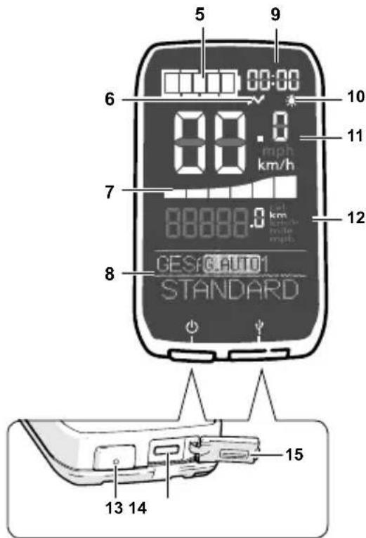
5 Charge status display
Shows the remaining charge of the e-bike battery.
6 USB-port symbol
Indicates when an external device (e.g. mobile phone) is connected to the display unit.
7 Operating assistance display
Graphic display showing the level of electrical support the rider is using. The more bars shown, the greater the electrical support the rider is using.
8 Text display
The operating assistance display shows the bike's current assistance modus, and the chosen gear (assuming your FLYER has a Di2 switch).
9 Time display
Shows the current time of day.
10 Light symbol
Shows that the lights are switched on
11 Speed display
Shows the current riding speed.
12 Display fi eld for secondary information
This fi eld shows secondary information such as the distance ridden, the total distance ridden, the highest speed, etc.
13 On/Off button
Switches the electrical support on and off.
14 Micro USB connector
You can use this port to charge an external device (e.g. a cell phone) using the cable supplied.
15 Rubber cap
Protects the Micro-USB connector.
16 Reset button
This button resets the kilometres-ridden display to "0".
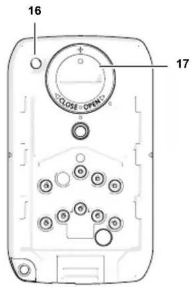
17 Lithium battery compartment
This compartment contains a button cell for the timer indicator.
Di2 control unit
18 Gear shifter (high)
By pressing this button, you will shift to a higher gear.
19 Gear shifter (lower)
By pressing this button, you will shift to a lower gear.

Even when you stop pedalling for a long period of time, the system will not automatically switch off.
5.2 Operation with laterally mounted display
Press the on/off button 12 on the display to activate the assistance function or the various indicators. Do not place your foot on the pedal while turning the power on! The assistance function of the motor switches on as soon as you start pedalling.
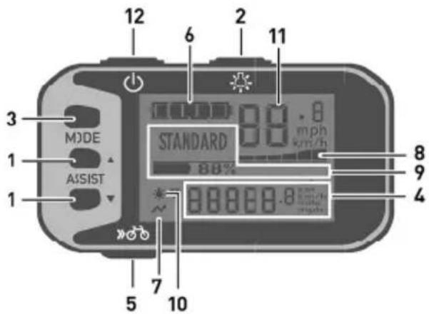
1 Selection key Assistance mode
Select the [HIGH], [AUTO], [STANDARD] or [ECO] assistance mode. Select [NO ASSIST] to deactivate the assistance function.
2 Light button
Scrolls through secondary information such as distance ridden, average speed ridden, maximum speed, total distance ridden etc.
4 Display field for secondary information
This field displays secondary information such as distance ridden, average speed ridden, maximum speed, total distance ridden and remaining range that can be covered in assisted mode.
5 Bike button
FLYERS with pedal assist up to 25 km/h are equipped with a pushing aid. This is limited to 6 km/h in the fastest gear. The FLYER can conveniently be moved out of underground parking or along steep paths by pressing the bicycle button. For certain models with pedal assist above 25 km/h, the bike button can be used to activate the setting-off aid, which is limited to 18 km/h. The installation is performed in compliance with national regulations.
6 Charge status display
Shows the remaining charge of the e-bike battery.
7 USB connection indicator
Indicates when an external device (e.g. mobile phone) is connected to the display unit for charging.
8 Assist power indicator
Displays in the form of a graph how much the rider is being assisted. The more bars shown, the greater the electrical support the rider is using.
9 Text display
Displays the current assist mode, the remaining battery capacity, and warnings and errors.
10 Light symbol
Shows that the lights are switched on.
11 Speed indication
Shows the current riding speed.
12 On/Off button
Switches the electrical support on and off.
Reset button (on the rear)
This button resets the kilometres-ridden display to "0".
5.3 Battery
1 LED charge status display
Shows the battery's remaining charge.
2 Control button for battery charge level
Let the LED battery charge level indicator blink to verify the remaining battery power.
3 Charger port
4 Rubber cap
Protects the connectors for the charger when the battery is not being charged.

Check whether the battery is fully charged after you have purchased it and before using it for the first time.
To check if the battery is charging, press the control button to be shown the battery charge level.
Charge the battery when none of the LEDs light up. Only use the original charger. Never use chargers supplied by third-party companies.
Charging status indicator
The charging status of the battery is indicated by five LEDs.
A fast-flashing LED indicates that the battery has been completely discharged.
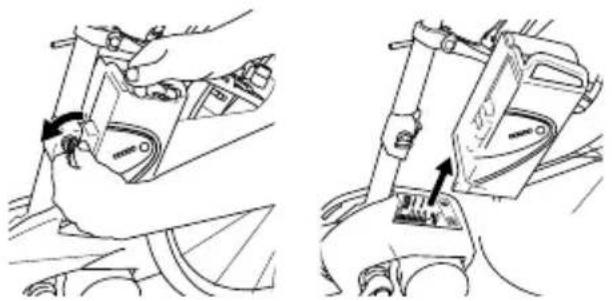
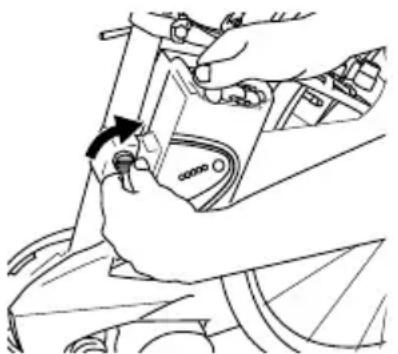
Removing the battery
1) Switch off the electrical system first. Press the on/off button for this purpose.
2) Unlock the battery with the battery key and remove it from the holder. Hold the battery firmly, as it is heavy.
natural_image
Technical line drawing showing two mechanical assembly steps with a hand adjusting a component (no text or symbols present)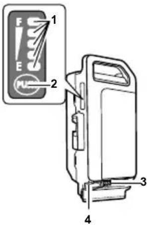
Loading the battery
The battery can be charged while it is installed in the e-bike or once it has been removed.
Charger
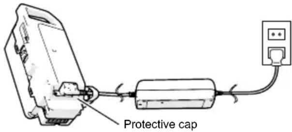
1) Remove the rubber cap
Open the rubber cap on the battery.
Connect the mains plug to a mains socket (220
V - 240 V AC) and connect the charger to the battery.

Do not connect the charger to the mains socket immediately after a sudden temperature change from cold to warm. It is possible that condensed water has collected on the contacts and this will lead to a short circuit. Do not connect the battery to the charger immediately after a sudden temperature change from cold to warm. Wait until both devices have reached room temperature before connecting the charger or the battery. Always charge and store the battery and the charger in a dry and clean environment.
2) Check the LED charge status indicator
Check whether the charge status LED is lit up.
The LED lights up according to the charge status.
The charge status LED goes off when the charging process has been completed.

The charging time takes longer if the battery temperature is too low or too high.
A fully charged battery cannot be charged any further.

The battery may not be recharged when it indicates a fault. The battery might be damaged after being dropped or due to mechanical impact, even when there is no visible external damage. Such batteries must therefore be inspected by a FLYER specialist retailer. Never try to open a battery or to repair it.
3) Remove the plug from the power outlet
Separate the mains plug from the mains socket after disconnecting the battery from the charger. It is important that the rubber cap is firmly reattached before using the battery.
Safety warning regarding the battery charger
The name plate refers to warning notes and other safety information in connection with handling the charger. It is important to read them before using the charger.

Use only the original Panasonic charger supplied along with your e-bike. Only this charger is designed for the lithium-ion battery used on your e-bike.

Completely charge the battery using the charger before the first ride to ensure full battery performance. Read and adhere to the operating instructions for the charger when loading the battery.
The battery can at any time be charged outside or installed in the bicycle without reducing its life span. Interrupting the charging process does not damage the battery.
The battery is equipped with a temperature monitor that permits charging only within a temperature range of 0 °C to 40 °C. If the battery temperature is too high, the battery will not charge. In addition, if you press the control button for the LED battery charge level, the LED at the very top [F] and bottom [E] will blink.
natural_image
Abstract pattern of star-shaped shapes with rounded corners and shaded inner rectangles (no text or symbols)Separate the battery from the charger and wait until it has reached operating temperature. Only reconnect the charger when it has reached the permitted operating temperature.
Inserting the battery
1) Inserting the battery
Place the battery into the lower holder of the e-bike and tilt its upper part towards the vehicle until the lock latches onto the upper holder. Ensure that the battery is correctly positioned in the holder.
natural_image
Line drawing of a hand adjusting a mechanical component with a black arrow indicating rotation (no text or symbols)
- Prevent extreme overheating due to external effects or overloading.
- Only use the battery with your FLYER.
- Never use a damaged battery. If you discover cracks, deformation of the housing or leaks, stop using the battery and have your FLYER checked by a specialist retailer.
- The lighting function will still continue for approx. one hour after the battery is empty.
5.4 Pushing aid
Your FLYER is provided with pushing assistance up to of 25 km/h. The pushing assisting will be activated for as long as you press down the bike button. It allows you to move your FLYER slowly at up to 6 km/h without pedalling. If you have to push the FLYER out of an underpass or a parking garage for example, this aid can be useful. Use your pushing aid only while walking next to the vehicle, hold the handlebars at all times with both hands and remain ready to brake. Do not use the pushing aid to ride the bike. The installation is performed in compliance with national regulations. Models with pedal assist above 25 km/h are partially equipped with a setting-off aid up to 18 km/h. (The setting-off aid is fitted in accordance with national regulations)
6. Legal requirements

However, the rules and regulations for e-bikes are constantly being revised and changed. Stay informed about changes in legislation in order to remain up-to-date.
For pedelecs and e-bikes, special provisions apply for their limit of use. This means that e-bikes are partly operated like a bicycle and other times not. Before riding on public roads with your FLYER, inform yourself on the current legal requirements enforced in your country. This information can be found at your FLYER retail store, the respective national bike or e-bike associations and online.
Here you can gather information on how your FLYER must be equipped in order to ride it on public roads.
The lighting system required to be installed or carried with you is also described. You will also be informed on which brakes the bike needs to be equipped with.
By reading up on current national regulations, you'll obtain information about the current age required to ride the bike and where it is allowed or must be ridden. The regulations for minors riding on public roads can also be found here. It will be made clear if a helmet is required to be worn by law.

Check whether your private third-party liability insurance covers possible damage caused by using an e-bike.
7. Intended use

The FLYER is intended for transporting one person only.
Carrying luggage is only permitted with appropriate equipment fitted on the FLYER. The maximum carrying capacity of the luggage rack as well as the maximum permitted weight of the vehicle may not be exceeded (see “Technical data”).

Permitted overall weight: Driver weight + FLYER weight + battery weight + luggage weight + trailer weight
E-bikes, city bikes and trekking bikes that are built according to national and legal standards, can be taken on the public roads and uneven terrain i.e. dirt roads.
Any liability or warranty provided by the FLYER retailer or manufacturer will not apply if you abuse or misuse the product by neglecting the safety information given to you. The same applies if the FLYER is overloaded, ridden on unsuitable terrain or if manufacturing defects are unprofessionally dealt with. The guidelines for servicing, care and storage must be observed in order to retain liability and warranty.
Your FLYER is not designed to withstand extreme use, i.e. riding down stairs, performing tricks/jumps/stunts or racing in official competitions.
FLYER e-bikes are not licensed for use in competitions and contests.
If you have any questions regarding the bike's limit of use, please don't hesitate to contact your FLYER retail store or manufacturer.
Before riding on public roads with your FLYER, inform yourself on the current riding regulations in your country. Only ride on pathways and trails that are permitted for vehicles.
8. Before the first ride
Ensure that the e-bike is ready for use and adjusted to fit your body.
This includes:
- Setting the position and fixture of the seat and handlebars
- Adjusting the brakes
- Securing the wheels into the frame and fork To ensure that you enjoy a safe and comfortable riding position, please allow your FLYER specialist retailer to set up your handlebars and stem. Have the saddle set to a safe and comfortable position (see Chapter 11.2.).
Have the brake handles set by the FLYER specialist retailer so that you can reach them easily at all times and can use the brake without getting tired. Be sure to familiarize yourself with the brake levers connected to the front and back wheels – the left brake lever is usually for the front wheel and the right lever is usually for the back one! Despite this general rule, however, you should still check what wheels the brakes are connected to since this standard isn't always followed.
Before each ride, and anytime your bike has been left unattended for a short period of time, make sure to check if each screw, quick-release lever, thru axel or other important components are properly secured where they belong. A table listing the most important screw connections and the prescribed fastening torques is provided in the "Technical Data", while notes on the correct use of quick release fasteners and quick release axles are provided in Chapter 11.1.
When you are driving with clipless/step-in pedals: Functional testing is required. The pedals should release easily and smoothly.
Check the tyre pressure. The manufacturer guide lines which may not be exceeded or undercut are printed on the side of the tyres.
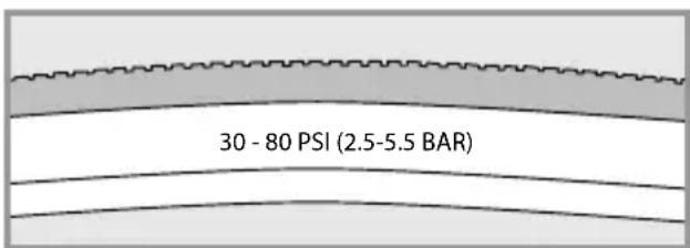
Example of tyre pressure information
It is also necessary for you to check the following components of your e-bike:
- Please check that the battery is secure.
- Check the charging state of the battery to ensure that the charge is sufficient for the drive planned.
- Familiarise yourself with the functions of the operating element.

Familiarize yourself with your new FLYER e-bike's riding and handling performance by testing its features out in a safe and quiet area.

Only use a FLYER with a frame size that suits you. Ensure that your legs have enough room to manoeuvre. You must be able to dismount quickly without touching the frame. Insufficient clearance or room to manoeuvre may lead to severe injuries.

Please note that while preparing to mount your FLYER that it will immediately start moving as soon as you put your foot onto the pedal when the support mode is switched on. Do not place your foot on the pedal when mounting. Hold the brake, as the unfamiliar thrust may otherwise lead to falls or other accidents. Stand to one side of the FLYER and lift your leg over the e-bike. Firmly hold the handle bars with both hands, as you would do with a bicycle. Always remember to fold in the prop stand before riding off.
natural_image
Illustration of a hand holding a tool, no text or symbols present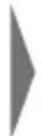
natural_image
Close-up of a person's legs and feet wearing a bicycle footset, no visible text or symbols
Modern brakes have a substantially higher braking performance than conventional brakes. Carefully practise using your brakes.
Note that when riding in wet conditions and on slippery roads, your bike's braking power, particularly the rim brakes, can be severely weakened. Expect a longer braking distance if you are riding in wet conditions. Look ahead while riding and familiarise yourself with the brakes' response time.
natural_image
Pure mechanical component diagram without any text, numbers, or symbols
If your pedals are produced with a rubber or plastic coating, first carefully familiarise yourself with the grip of the pedals. The pedals may be very slippery under wet conditions. Use safe terrain without traffic to familiarise yourself with system pedals or clipless pedals.

Please note that the weight distribution of the e-bike is significantly different from that of a bicycle without electrical drive. The weight of an e-bike makes parking, lifting, carrying or pushing up-hill more difficult.

Take note that your FLYER must be equipped according to the legal requirements if it is to be used in public road traffic.

Check with your insurance whether your vehicle and possible risks of handling lithium/ion batteries are sufficiently covered.
9. Before each ride

Please check your FLYER before each ride, as even after assembly, briefly leaving the bike in public places or transporting it may cause functions to change or parts to become loose.
Before every ride, please check that:
- The lights are working properly and are safely secured.
- The bell is working safely and is properly secured.
- The brakes are working properly and are secure, and you have checked for wear on the pads and braking surfaces. For hydraulic systems: Check the cables and connections for leaks.
-
Check that the tyres have the correct air pressure. Please note the specifications in Chapter "Tyres and tubes" (12.2). These are also printed on the outside wall of the tyres.
-
Check the tyres for damage, wear, brittleness, foreign objects and sufficient profile depth.
- Check the wheels for true running and damage.
- Check that the wheels are safely and correctly attached by fastening nuts or quick release fasteners and axles.
- Check that the gear shift components are working and are safely secured.
- All quick release fasteners and quick release axles (even after a brief period left parked and unattended), as well as screws and nuts to ensure they are firmly attached.
- Check the frame and fork for damage, deformation, cracks and dents.
- Check that suspension elements are working properly and are safely secured.
- Check that handlebars, stem, seat post and seat are secure and correctly positioned.
- Battery charge.
- Check that the battery is correctly and securely attached.

If you are not sure that your FLYER is in perfect technical condition, do not start your ride. Have your FLYER first inspected and repaired by a FLYER specialist retailer. If you subject your FLYER to intensive use (in sporting or daily use), we recommend regular inspection and repairs by your FLYER specialist retailer. Inspection procedures and intervals are specified in Chapter 23. All components of the FLYER are safety-related and have a specific service life. Exceeding this service life can lead to unexpected failure of the components. This can lead to falls and serious injury.

The vehicle is subject to wear and high stress as are all other mechanical components. Depending on the degree of stress imposed on them, different materials and parts may react differently in terms of wear and fatigue. A part may suddenly fail and cause injuries to the driver when its designed service life is exceeded. Any kind of cracks, scratches or colour changes in high-stress areas are an indicator that the service life of the component has been exceeded and that it should be replaced.

It is essential to have your FLYER checked by a FLYER specialist retailer after a fall or when your FLYER has fallen over.
Many components cannot be safely repaired and components may be damaged in a way that you cannot recognise.

Do not forget to take a high-quality bike lock with you on the ride so you can park and lock your FLYER to an immovable object. Separately lock the components that are fastened with quick release fasteners (e.g. the front wheel) as required. This will prevent theft of these add-on parts.
10. After a fall
Have the vehicle and all components checked for changes, damage, firm attachment and correct function by a FLYER specialist retailer. This may, in particular, include dents and cracks in the frame and fork, bent components and parts such as the handlebars or a shifted or turned seat. In -spection by a FLYER specialist retailer must cover the following main points:
- Carefully check the frame and fork. Deformations can usually be detected when looking at surfaces from different angles.
- Are the seat, seat post, stem and handlebars still in their correct positions? When this is not the case, do NOT move the components back from their changed position before loosening the relevant screw connection. It is essential to adhere to the prescribed fastening torque. Values and information are provided in the “Technical Data” and in the “Quick release fastener” chapter (11.1).
- Check whether both wheels are correctly and firmly attached to the frame and fork, that both the front and rear wheels rotate freely and that the rim runs straight past the brakes without snagging. The tyres must not touch the brakes. Experts can see from the distance between the frame or fork and the wheel whether the wheel turns without snagging.
- Check that both brakes are operating fully.
-
Do not set off again without having checked that the chain is sitting securely on both the front chain wheel and rear sprockets. It must be engaged fully with the cogs. If you set off and the chain jumps off a cog you may fall, at the risk of very severe injury.
-
Check whether the display of the FLYER e-bike shows a fault message or a warning. Do not drive your FLYER when a warning is displayed. Immediately contact your FLYER specialist retailer.
- Check that the display and the battery are undamaged. Do not ride your FLYER if there are any noticeable changes (cracks, scratches, etc.). Have all parts and functions first checked by your FLYER specialist retailer.

There is a risk that humidity or water may penetrate the motor if the housing of your battery is cracked. This may lead to short circuits or electrical shocks. Immediately stop using the battery in this case and contact your FLYER specialist retailer. Do not charge the battery.
If you notice any changes to your bicycle, DO NOT continue cycling. Do not retighten any loose parts without first checking them and always use a torque wrench. Take the FLYER to your FLYER specialist retailer, describe the fall to them and have the bicycle checked out!
11. Adjusting the bike to the rider
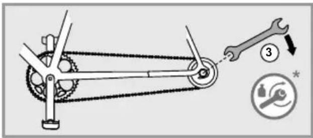
Installing pedals
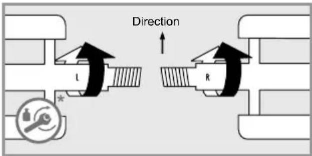
Always have your pedals installed or changed by your FLYER specialist retailer, and feel free to ask for advice their correct handling. Pedals must be installed with a suitable spanner. Please note that the two pedals are screwed on in different directions and must be fastened with high torque (see "Technical data"). Apply assembly grease to both threads.

natural_image
Mechanical linkage diagram showing lever mechanism and safety symbols (no text labels)Please take note that the right pedal is different from the left. You can recognise which pedal belongs on which side from the screws which turn in opposite directions. Usually, an "R" is embossed on the right pedal with an "L" on the left. Screw the right pedal clockwise and the left pedal anti-clock wise into the cranks.

The pedals must be fastened with a suitable spanner. Adhere to the correct fastening torque when screwing on the pedals, see "Technical data". Ensure that the pedals are fitted straight. If they are fitted at an angle, there is a danger of breaking and of having a fall!

For safety reasons, we strongly advice not using pedals with clips or straps.

Ensure that you have read the manufacturer's instructions before using magnetic or clipless pedals. Practise clipping your shoes in and out of the pedals' locking system before your first ride in a quiet, safe place. Clipless pedals which do not properly release are a safety hazard.

The release force of system pedals can be adjusted. Please test this on your first ride with a setting that releases easily. Regularly clean the system pedals and service them with a suitable lubricant.
11.1 Operating quick releases and axles
The wheels, seat post, seat, stem and handlebars may be attached with quick release fasteners, quick release axles or screw connections.

Only allow your FLYER specialist retailer to perform work on quick release fasteners and quick release axles. These are components which are crucial for your safety, so incorrect work and tools in this area of the bicycle could lead to serious falls.
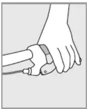
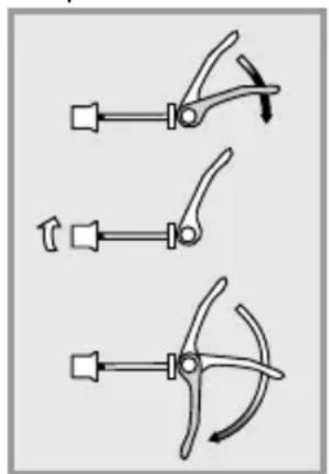
Quick release
Quick releases are clamping brackets which attach components like a screw, however their clamping force stems from tightening the lever without tools. The clamping force is activated by opening and closing the lever. The clamping force is adjusted by turning the counter nut when the lever is open.
- In order to open a quick release, to adjust the seat post for example, open the quick release lever.
- Now you can move and adjust the seat post.
- The quick release fastener must be closed before using the FLYER. Completely fold down the quick release lever for that purpose. Fully engage any possible safety devices.

The quick release is only securely closed when you need the power of the ball of your hand to close the lever.
The adjustment nut of the quick release fastener must be tightened when the tightening force is not high enough, e.g. when the seat does not stay in position. To do this, the quick release lever must be open.
natural_image
Three mechanical clamp or clamping tool illustrations showing different configurations (no text or symbols)Loosening the Adjusting Nut

natural_image
Three diagrams showing a tool with curved blades and arrows indicating motion (no text or symbols)Tightening the Adjusting Nut
The quick release fastener cannot be closed when the tightening force is too high. Open the clamping lever in this case and slightly loosen the adjustment nut.

- All quick release skewers must be firmly closed before you set off.
- Check all quick release fasteners for correct attachment if the vehicle was parked for a short time without supervision and before every ride.
- A closed quick release fastener must be folded close to the frame, fork or seat post.

Lock down wheels or other parts of your vehicle that are attached with quick release fasteners when you park your bicycle.
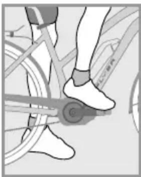
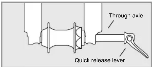
Quick release axles
The current chassis is either equipped with quick release fasteners, screw connectors or quick release axles that work in the same way as quick release fasteners:
The axle is screwed into the dropout and holds the hub between the fork legs. The hub and the axle are fastened with a quick release lever. Systems in which the axle is only inserted or screwed in and then fastened with a screw also exist. Refer to the attached component manufacturer instructions and allow your FLYER specialist retailer to explain the system to you in detail.

Ask your FLYER specialist retailer to explain in detail how the wheels and all relevant parts are to be correctly and safely attached using the quick release fastener or quick release axle system installed.

Inappropriately installed wheels may shift while you are driving or detach from the vehicle. This may damage the vehicle and lead to severe or life-threatening injuries to the driver. It is therefore important to take note of the following instructions:
Ensure that the axle, the dropouts and quick release mechanisms are free of dirt. Take care that they are correctly attached at all times.
Contact your FLYER specialist retailer and have your vehicle checked when you are not sure.

Check that all quick release fasteners and quick release axles are firmly attached, even if your FLYER only remained unsupervised for a short time. You may only start driving when all quick release fasteners are firmly closed.
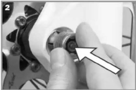
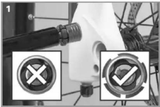
Suntour Q-Loc axle
Installation
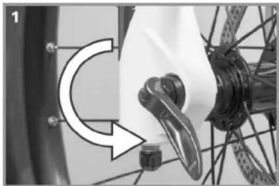
- Check the fl ange and open the lever fully before installation
natural_image
Close-up of a bicycle wheel assembly with two circular button symbols (X and ✓) highlighted, no readable text or labels present.- Push in the axle until it clicks
natural_image
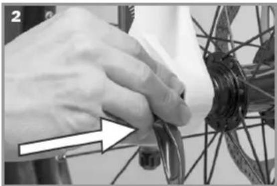
Close-up of hands operating a bicycle wheel rim, with a white arrow pointing to the handle (no text or symbols visible)- Adjust the tension with the lever half open until the fl ange fi ts closely
natural_image
Close-up of a hand adjusting a mechanical component with an arrow and plus symbol (no readable text or symbols)- Close the lever fully. Check the fit and retighten if necessary

natural_image
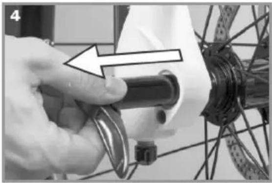
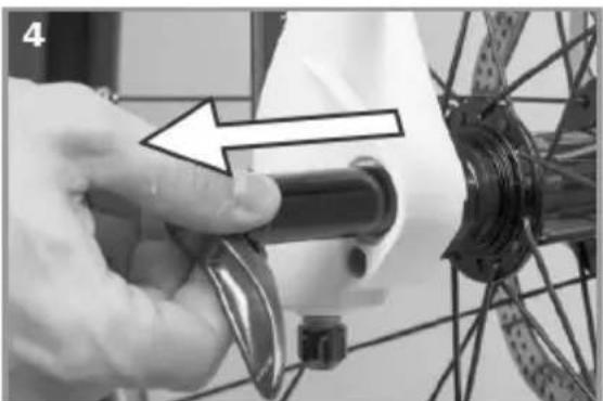
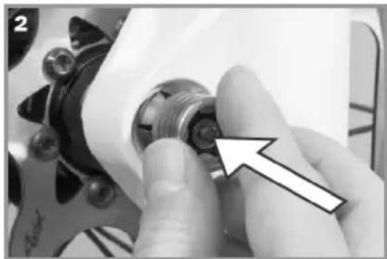
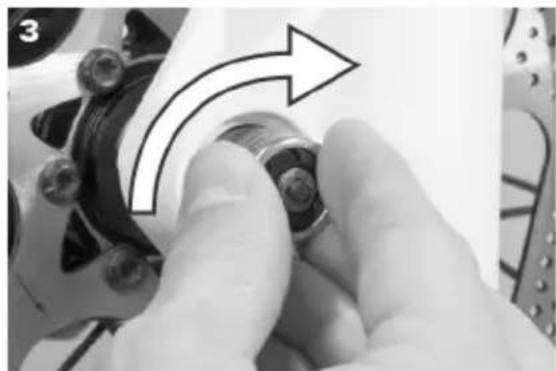
Close-up of a bicycle wheel assembly with a white component and a curved arrow indicating rotation (no text or symbols)Removal
natural_image
Close-up of a bicycle wheel assembly with a hand adjusting the wheel (no visible text or symbols)- Open the lever fully
natural_image
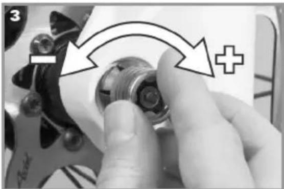
Close-up of a hand adjusting a mechanical component with a white arrow pointing to the part (no visible text or symbols)- Push the nut until the fl ange retracts
natural_image
Close-up of a hand adjusting a mechanical component with an arrow indicating rotational motion (no text or symbols visible)- Turn the nut clockwise until the fl ange remains locked in place
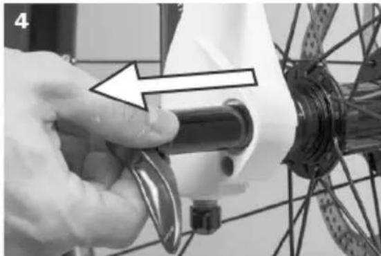
4. Pull out the axle
natural_image
Close-up of a hand adjusting a bicycle wheel component with a tool, no visible text or symbols11.2 Setting up the seating position
The seat, handlebars and stem must be adjusted to your body mass and the desired sitting positon in order to use your FLYER safely and comfortably.

Only allow FLYER specialists to work on your handlebars and stem. These are components which are crucial for your safety, so incorrect work and tools in this area of the bicycle could lead to serious falls.

The seat and stem can be attached with screw connections or quick releases. Always secure screw connections with the correct torque, see "Technical data".
Seat height
In order to transfer the pedal force effectively to the pedals, you must set your seat to the appropriate height.
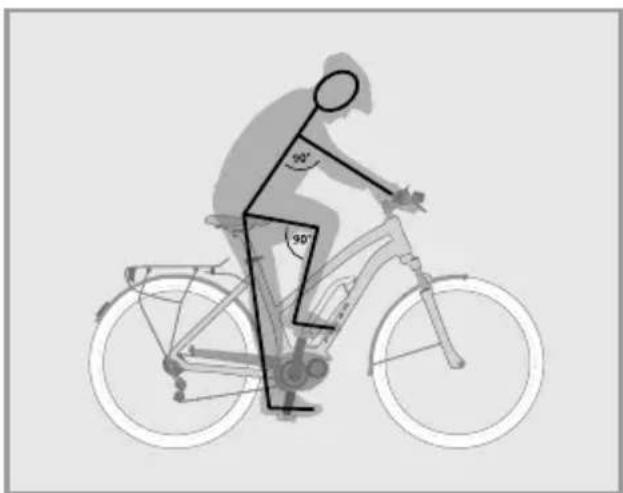
Find the ideal position by sitting on the FLYER and placing the heel of your foot onto the pedal in its lowest position.
natural_image
Silhouette of a person riding a bicycle with 90-degree angle annotations (no text or symbols on the diagram itself)90° arm-upper body angle
Now the bottom leg should be stretched. If this is not the case, dismount, adjust the seat in the required direction and try again.
Ensure that the quick release fastener is completely closed after the adjustment process.

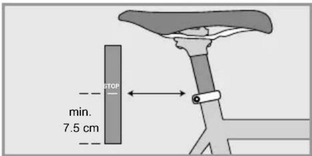
There are markings on the seat post which show how far it can be pulled out of the frame. Never pull the seat post beyond the maximum length marking. Otherwise the seat post may buckle or break. If you require a longer seat post to reach the correct sitting position, talk to your FLYER specialist retailer. Never ride with a seat post extended further than the maximum marker as this could result in serious falls and injury.

Children and persons who are not confident cyclists should be able to touch the ground with the tips of both feet. Otherwise, when stopping they run the risk of falling and suffering serious injury.
Seat position
The horizontal position of the seat can and should be set too.
You are in the optimal driving positon when your front knee is directly above the pedal while the crank is horizontally aligned.
The horizontal adjustment of the seat may only be performed within the markers and within the range specified by the manufacturer.

Test whether the seat post and the seat are firmly attached before you drive off. To do this, hold the seat at the front and back and attempt to turn it. It should not move.
Height of the handlebars
Once the seat has been firmly and comfortably positioned, the handlebars must be adjusted to your needs.
An effective starting position for relaxed riding is offered by a seating position in which the upper body and arm form a 90° angle.
In order to change the height of the handlebars, the height of the stem must be adjusted.

Allow your FLYER specialist retailer to adjust the settings of the handlebars and the stem.
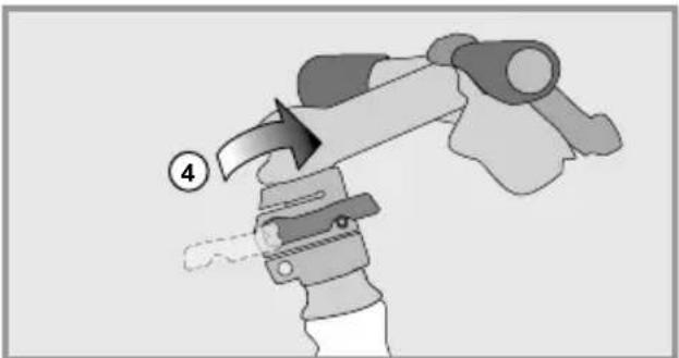
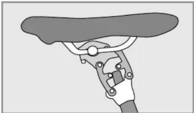
Speedlifter Twist
The Speedlifter allows you to adjust the height of the handlebars in only a few movements. The Twist system makes it possible to turn the handlebars 90 degrees to save space while transporting your FLYER.
Open the quick release lever of the Speedlifter (1)
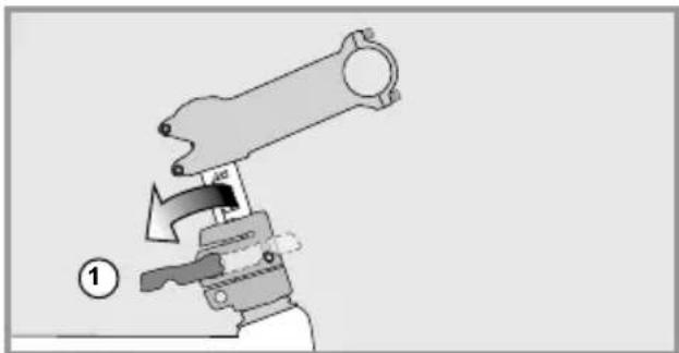
natural_image
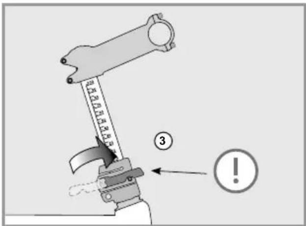
Mechanical assembly diagram showing a lever mechanism with a handle and pivot point (no text or symbols)Move the handlebars to the desired position (2).
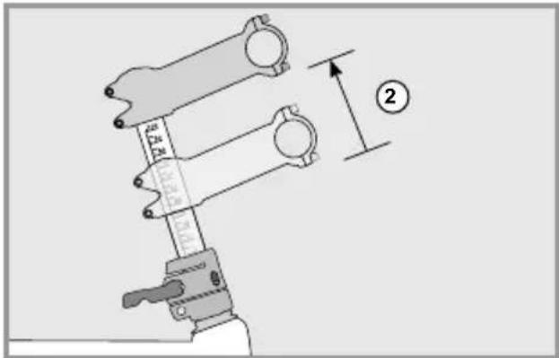
Close the quick release lever completely to fasten the handlebars (3).
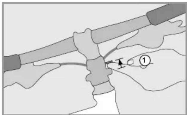
Open the quick release lever in order to turn the handlebars sideways (1).
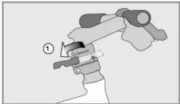
natural_image
Illustration of a hand holding a mechanical device with a numbered label (1) indicating step 1, no text or symbols present.Lift the unlocking bolt (2).
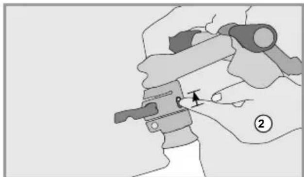
natural_image
Mechanical assembly diagram showing a hand operating a clamp or clamp device with a pointer indicating motion (no text or symbols present)The handlebars can now be turned sideways (3). The bolt automatically latches in the 90-degree positon (4). Completely close the quick release lever so that the handlebars are safely fastened.
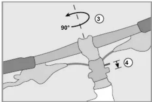
Turning back the handlebars: Lift the unlocking bolt (1).
natural_image
Illustration of hands performing a manual task with tools and a numbered step (no text or symbols)Then turn the handlebars back to the driving position (2). The bolt must be re-latched (3).
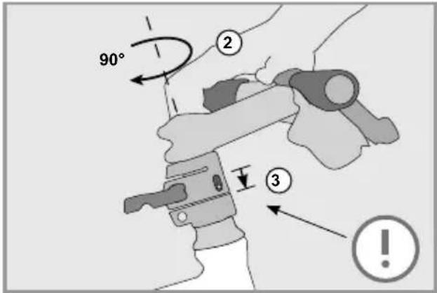
Completely close the quick release lever (4).
natural_image
Illustration of a robotic arm with a handle and motion indicator (no text or symbols)
The Speedlifter quick release lever must be completely closed during the ride, just like any other quick release fastener. It must also be ensured that the unlocking bolt is latched in the front hole. Never adjust the handlebars while riding.

Read the instructions of the component manufacturer and for more information visit: www.speedlifter.com.
Adjusting the stem

For detailed information, please read the instructions supplied by the manufacturer. Only allow FLYER specialists to work on your handlebars and stem.
The following stem types are installed on FLYERS:
A head stem
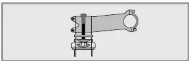
natural_image
Technical line drawing of a mechanical assembly (no text or symbols)Adjustable stem
The incline of the stem can be adjusted to your requirements. The lateral fastening screw must be loosened and retightened with the correct fastening torque after adjustment
Adjusting the bike's stem angle.
To adjust the bike's stem angle and with it the position of the handlebar, unscrew the top 3 Allen screws with a few rotations. Do not completely unscrew the screws.
At this point, you should be able to adjust the stem to its right angle. Having done that, tighten the Allen screws back with the prescribed tightening torque.
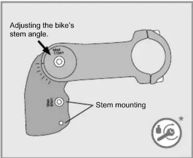

Changing the position of the stem also changes the position of the handlebars. You should always be able to safely reach and use grips and controls. Handles with a pronounced wing shape may need to be repositioned. Make sure that all cables and leads have a sufficient length to allow for all possible steering movements when changing the handlebar and stem position.
11.3 Setting up the brake levers

The brake levers should be set up so that your hands can safely and comfortably apply them as a straight extension of your arms.

Check before your first drive which brake lever brakes which wheel.
Some models allow adjustment of the grip width so that brake levers can also be safely gripped by smaller hands. Always have brake adjustments performed by a FLYER specialist retailer as they concern safety-related components.
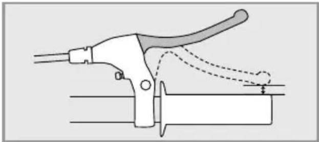
natural_image
Diagram of a manual tool with handle and lever mechanism (no text or symbols)The brake levers must be adjusted to ensure that they do not touch the handlebars, even when they are pulled hard.
11.4 Suspension elements
The chassis must be adjusted to the driver's weight and type of use by a FLYER specialist retailer to ensure appropriate function of the suspension elements.

Please note that the suspension may need be reset if you ride with heavier loads, for example during a cycle tour.
Suspension seat posts have proven their value in both daily use and on tours.
natural_image
Illustration of a hand holding a bicycle tire with a handle (no text or symbols)Some suspension seat posts can be individually adjusted to fit the driver. Ask your FLYER specialist retailer for details.

Suspension and chassis components are vital parts of your FLYER. Service and check your FLYER suspension at regular intervals. Have your FLYER inpected by your FLYER specialist retailer at regular intervals.
The chassis will be more effective and last longer if it is cleaned on a regular basis. Warm water with a light cleaning agent is suitable for cleaning this part of the bicycle.
12. Wheels and tyres
The wheels are subject to a great deal of strain through the uneven characteristics of the ground and the weight of the rider.
• After the first 200 kilometres, the wheels must be checked by a specialist and re-centred if necessary.
- The tension of the spokes must be checked at regular intervals. Loose or damaged spokes must be retightened or replaced by a FLYER specialist retailer.
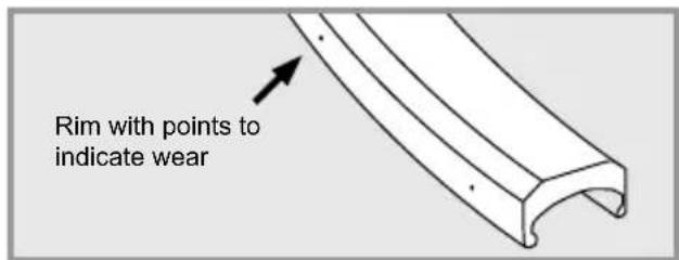
12.1 Checking the rims
The rim is subject to wear when a rim brake installed.


A severely worn rim is less stable and more prone to damage. A bent, torn or broken rim may lead to major accidents and severe falls. Do not continue to use your FLYER if you notice damage to one of the rims. Please allow a FLYER specialised retailer to check the rims.

The rims for rim brakes are marked to show where the brakes rub against the rim. On the rim surface there are points or grooves which help you gauge the level of wear.
The rim must be changed when the points or grooves can no longer be seen in one or several places. Have the rims regularly inspected by a FLYER specialist retailer, especially when replacing/exchanging brake pads.
12.2 Tyres and inner tubes

Tyres, like many other parts, are subject to wear and tear. Check the profile depth, tyre pressure and state of the lateral tyre surfaces at regular intervals and take note of signs of brittleness or wear.

Do not exceed the maximum tyre pressure recommended when inflating the tyres. Otherwise this could lead to a tyre exploding.
The tyres must be pumped up with at least the stated minimum tyre pressure. The tyre might detach from the rim if the tyre pressure is too low.
The values for the permitted maximum and minimum pressure are imprinted on the lateral tyre surface.
Tyres may only be changed for identical, original tyres. The bicycle's handling could otherwise be negatively affected. This may lead to accidents.

You should only replace damaged parts with original spare parts.
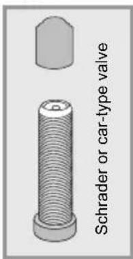
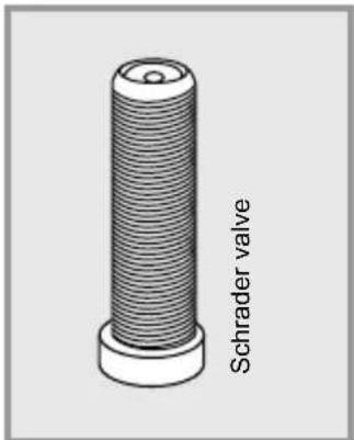
Most FLYERS use car-type valves or Schrader valves. This valve type allows you to top up the tyre pressure of your FLYER e-bike at most filling stations. Specialist retailers will let you know which type of air pump fits your car-type valves. Tubes may only be changed for identical, original tubes.
12.3 Dealing with a flat tyre
Correct and safe repair of a flat tyre requires specialised e-bike knowledge and special tools. Have technical defects and flat tyres exclusively repaired by your FLYER specialist retailer.

Repairing a tire puncture involves having to adjust safety-relevant components. Incorrect mounting of the wheels and brakes can lead to severe falls and injuries. We strongly advise you not to repair a tire puncture alone. Ask your FLYER retailer to fix the tire puncture for you.

Get thorough instructions from your FLYER specialist dealer and practise changing the wheels and tyres under their supervision if you plan to repair your own flat tyres. The system must be switched off and the battery must be removed before changing a tyre or wheel.
You need the following equipment to repair a tire puncture:
- Plastic tire lever
- Patches
- Rubber cement
- Sandpaper
- Open-ended spanner or wrench (for wheels without quick release skewers)
- Air pump
- Spare tube
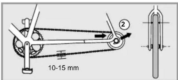
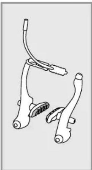
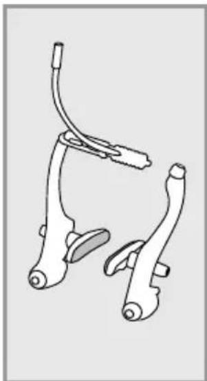
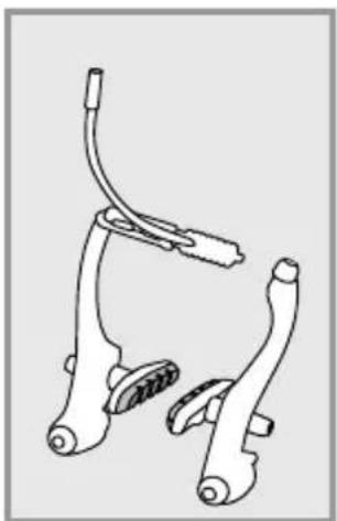
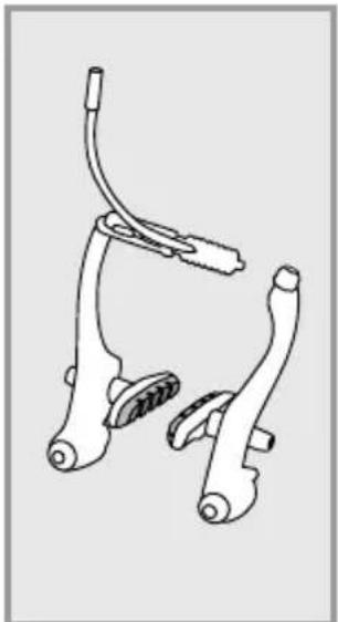
If your FLYER is equipped with a rim brake as a V-brake, proceed to open the brakes as follows:
- Hold the wheel with one hand.
- Press the brake arms together against the rim
- Hang the bowden cable of the brake or the outer sheath of the bowden cable over one of the brake arms

When removing the front and rear wheel, make sure the pull cable is loosened.
If your bike is equipped with hydraulic rim brakes, proceed to remove the brakes as follows:
- If you have quick releases for the brakes, you can demount a brake unit according as instructed in manufacturer's instructions. (See also p. 156)
- If you do not have a brake quick release, deflate all of the air out of the tyre.
If your FLYER is equipped with a disc brake, you can remove the wheel without further preparation. Please note: when fitting the wheel, the disk must be slotted between the brake linings of the brake calliper and ultimately be centred without contact.
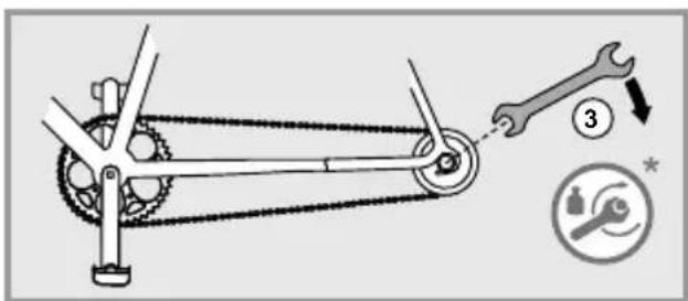
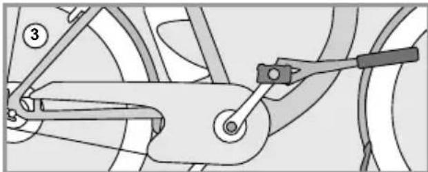
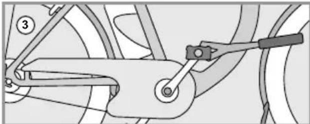
In the case of back pedal brakes, the screws on the brake arm of the chain stay have to be opened.
-
Removing the Wheel
-
If your bicycle has quick-release levers or axles, open them.
- If your bicycle has hexagonal bolts, then loosen them in anti-clockwise direction with a fitting ring spanner or box-end wrench.
You can then remove the front wheel according to the steps listed above.

Source: Shimano® techdocs
The following applies for rear wheels:
- If your bicycle uses a derailleur gear system, change gear to the smallest sprocket. In this position, the rear derailleur poses the least hindrance in removing the wheel.
- If your bicycle has quick-release levers or axles, open them.
- If your bicycle has hexagonal bolts, then loosen them in anti-clockwise direction with a fitting ring spanner or box-end wrench.
• Pull the rear derailleur backwards somewhat. - Lift the bicycle slightly.
- Lightly strike the wheel from above with the palm of the hand.
• Take the wheel out of the frame.
If your bicycle has a gear hub, please consult the instructions supplied by your manufacturer for removing the wheel.
The valve to your FLYER e-bike's inner tube
3. Removing the tyre and inner tube
- Unscrew the valve cap, the fastening nut and possibly the cap nut from the valve.
- Release all of the remaining air from the inner tube.
- Insert the tyre lever opposite the valve on the inside of the tyre.
- Insert the second tyre lever approx. 10 cm from the first, between the rim and tyre. Lift the tyre wall over the edge of the rim.
- Repeat this lifting action around the wheel until the entire tyre is free.
- Remove the inner tube from the tyre.
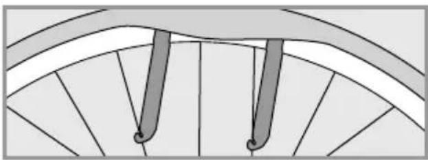
natural_image
Diagram of a fan blade with two vertical bars and a central loop, no text or symbols present4. Change the inner tube
Switch the inner tube for an intact one.

Tubular tires and tubeless tires must be changed according to the tires and rims' manufacturer's instructions.
5. Reassembling the tyre and inner tube

Please avoid allowing foreign bodies inside the tyre. Ensure that the inner tube does not have any folds and is not squashed.
Ensure that the rim tape covers all spoke nipples and does not have any damage.
- Place one edge of the rim into the tyre.
- Push one side of the tyre completely into the rim.
- Insert the valve through the valve hole in the rim and put the inner tube into the tyre.
- Pull the second side of the tyre into the rim with the balls of your hands.
- Ensure that the inner tube is correctly positioned.
- Pump the inner tube up somewhat.
- Check that the tyre is properly in place and runs true using the control ring on the side of the tyre. Adjust the positioning of the tyre with your hand if it does not quite run true.
- Pump the inner tube up to the recommended tyre pressure.

Please take note of the running direction of the tyre when installing it.
6. Reattaching the wheel
Reattach the wheel securely back in the frame or fork with the corresponding quick release, bolted connection or full floating axle mechanism.

If your bicycle has disc brakes, please ensure that the brake discs are correctly secured between the brake pads!
Read the gear manufacturer's instructions to correctly and safely assemble and set up derailleur gear systems, gear hubs and combined hub and derailleur gear systems.

Tighten all screws to the recommended torque. Failing to do so could cause the screws to tear and components to come apart.
- Connect the brake line, attach it or close the brake quick release.
- Check if the brake pads are aligned with the brake surfaces.
- Securely attach the brake arm.
- Test the brakes.
13. Bicycle gears
The gear shifters regulate the necessary cycling power and speed. While riding in lower gears, it becomes easier to ride on inclined planes and it reduces physical exertion when pedalling. While riding in higher gears, more physical exertion is needed to pedal, allowing you to reach higher speeds with lower pedalling cadence.

Ask for detailed instructions regarding the operation and the special features of the e-bike's gear system from your FLYER specialist retailer, even if you are an experienced cyclist. Practise on an even and safe terrain.
If you have any questions about assembling, maintaining, setting up or operating the gears, please contact your FLYER specialist retailer. Read the operating instructions on the website of the respective manufacturer.

Despite a perfectly set up chain gear system, a bike chain crossing at an angle can lead to noises during riding. These noises are normal and do not cause any damage to the gear components.

Do not pedal backwards while changing gears, as this may damage the gear system.

Using faulty, incorrectly set-up or worn gear components is dangerous and can lead to falls. If you are concerned, have components checked and readjusted as required by a FLYER specialist retailer.

Electronic gears
Especially with electronic gears, operating them may be unusual. Therefore, you may want to ask your FLYERretailer for more information and about this.
14. Bicycle chain and sprocket
Bicycle chain maintenance
Bicycle chains are wearing parts. The degree of wear varies considerably. Have the chain of your FLYER regularly checked by your FLYER specialist retailer.
• Hub gears: approx. 3000 km
- Chain gears: 1500-2000 km

A worn bike chain can break and cause very serious falls. Worn bicycle chains must therefore immediately be changed by your FLYER specialist retailer.
Regularly care for your bicycle chain by cleaning and greasing it. These measures reduce prema-ture wear.

To ensure that the chain and gears can work safely, the chain must have a certain level of tension. Chain gear systems tense the chain automatically. In the case of hub gears, chains which are too loose must be tightened. It might other - wise jump off the gears and lead to a fall.
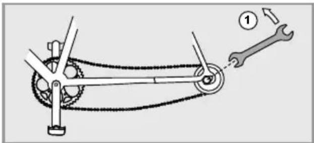
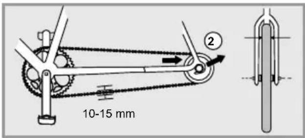
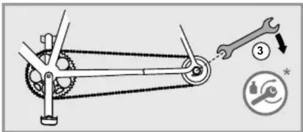

The axle nuts and the brake anchor plates of back pedal brakes must be correctly fastened after each chain adjustment process.

The chain may only be tightened once the electrical system has been switched off and the battery has been removed. If the chain of your FLYER e-bike has fallen off the chain ring or sprocket, it is essential to switch off the electrical system and remove the battery before placing the chain back on the gear wheels.
Tightening the chain on a Tandem

If you own a FLYER Tandem, ensure that the chain between the two lower bearing brackets has the correct tension. Only allow your FLYER specialist retailer to adjust the chain of your FLYER Tandem.
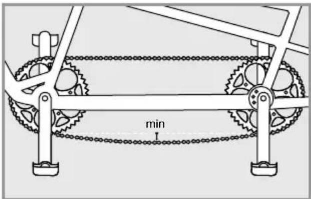
Switch off the system and remove the battery. Turn the crank set into the position where the tension of the chain is greatest or where the chain sag is least.
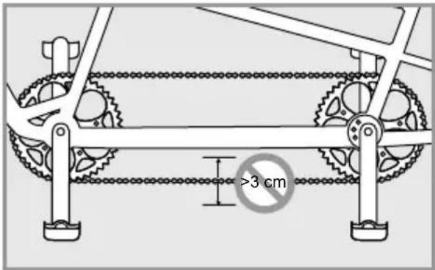
In this position, you should be able to move the chain 2 to 3 cm freely, without forcing.
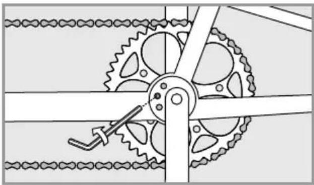
natural_image
Mechanical gear mechanism diagram showing interlocking gears and linkages (no text or symbols)If the tension of the chain is too high or too low, the fixture of the bottom bracket eccentric loosens.
In your FLYER Tandem, the eccentric is clamped internally. The fixture is administered using an Allen key screw from the side.

Only loosen this screw with two or three turns anti-clockwise - do not completely unscrew it.
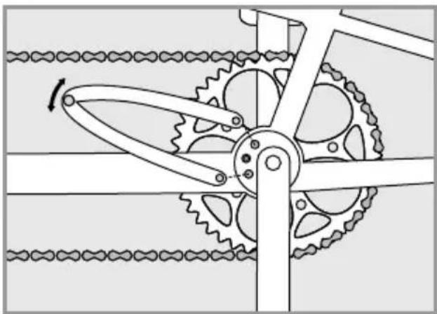
natural_image
Mechanical gear mechanism diagram showing interlocking gears and chains (no text or symbols)Use a pin spanner to turn the eccentric until the correct chain tension is achieved.

The eccentric can be turned to the left or right to achieve the correct chain tension. The crank is not attached in the middle of the eccentric. Rotating the eccentric therefore changes the crank position and the seat height. After the chain tensioning process, the centre of the lower bracket bearing should be above the middle line of the eccentric when a lower seat height or additional ground clearance is required. The crank position is then shifted upwards. It is normally recommended to turn the eccentric in the opposite direction, so that the centre of the lower bracket bearing is below the middle line of the eccentric once the chain tensioning process has been completed.
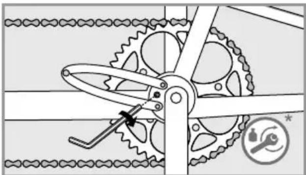
natural_image
Mechanical gear mechanism diagram showing pulley, chain, and gear assembly (no text or symbols)Finally, tighten the screw on the side of the bottom bracket.
While doing this, hold the eccentric tight with a pin spanner, so that it does not move while tightening the screw.
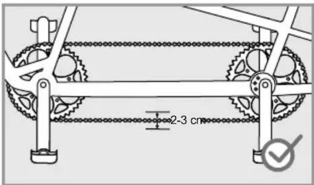
Check the chain again for the correct tension.
15. Brake

Brakes are vital to your safety on the bicycle. Have the setting and maintenance work performed by your FLYER specialist retailer. Only original spare parts may be used. Otherwise it is possible that the functionality of your FLYER e-bike may be impacted or damaged. No modifications of the brake system are permitted.

The braking effect of modern brakes is very strong. You must get used to the braking performance of the new brakes. Activate the brake carefully. You should practise emergency braking in a safe, traffic-free area so that you can safely handle your FLYER even during very intense braking manoeuvres.

Source: Shimano® techdocs

Do not brake continuously or too hard on long downhill section, as your brakes might overheat leading to reduced braking power. Alternate between applying the front and back brake on long and steep downhill sections to allow the other brake to cool. It is preferable to brake sharply for a shorter time when taking bends or if you are riding too fast. This allows the brakes to cool down in the meantime. This preserves your braking power. The only exception is if you are cycling in slippery conditions such as on sand or a smooth surface. You should then exercise great care, slowing yourself down using the rear brake. Otherwise there is the risk of the front wheel slipping out to the side and causing a fall. Take regular breaks during long downhill sections to give the brakes sufficient time to cool down. Do not touch the brakes for at least 30 minutes after riding as they can become very hot.

Almost all modern brakes provide considerably more braking power than was available for bicycles in the past. Carefully familiarise yourself with the brakes, practising using them and practise emergency braking, starting on safe ground with no traffic before setting out into the traffic. Look ahead while riding. Only use original spare parts. Otherwise it is possible that the functionality of your FLYER e-bike may be impacted or damaged.
Adjust the brake lever to ensure that it does not touch the handlebars when pulled hard.
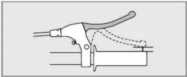
natural_image
Diagram of a manual tool gripping a mechanical component with dashed lines indicating motion (no text or symbols)Back pedal brakes
If your FLYER is equipped with back pedal brakes, brake by pushing the pedals backwards instead of forwards. This means that your bicycle will not freewheel and you are unable to rotate the pedals backwards freely as you otherwise can.

Back pedal brakes work best when both cranks are in a horizontal position. If one crank is pointing up and the other one down, less force can be applied and braking is less effective.

The effectiveness of back pedal brakes can deteriorate substantially on long inclines. This type of braking system can become very hot from continuous braking. You should also use the rim brakes to slow down on long inclines. Wait until the back pedal brake has cooled down and do not touch the brake drum.

Ensure that the brake anchor plate is correctly attached with the appropriate screw when removing or installing it.
Rim brakes (V Brakes)

The braking action for modern rim brakes is very sensitive. You will have to get used to the braking action for V Brakes Activate the brake carefully. You are recommended to practice using the emergency brakes. By doing this, you will be prepared to safely stop your e-bike when needing to brake sharply.

When removing the front and rear wheel, make sure the pull cable is loosened.
Using additional spring elements inappropriately in the braking system (power moderators) may lead to severe falls.
Adjusting the brakes
Your retailer will properly adjust your FLYER before giving it to you. There should be a gap of circa 1-1.5 mm between the brake pad and the rim. Due to the wear done on the braking pad over time, the gap between the rim and the brake can grow larger, requiring more pressure when using the brake. For this reason, you are strongly recommended to check this gap periodically and adjust the brakes whenever the lever requires too much pressure or the brakes aren't working properly.
You can check the amount of wear on the braking pads by checking the indents on the brake pads. If these indents are not visible anymore, bring your FLYER to a retail store to replace the brake pads.
To check if your brakes are functioning properly, do as follows:
- While pushing your e-bike forward, press the front and rear brake levers one by one as if you were sharply braking while riding.
- The front wheel should break in a delayed fashion, causing the back wheel to lift from the ground.
- The back wheel's braking action should be so powerful that it stops the motion of the bike.
Adjusting the brake pad's distance to the rim
To adjust the brake pad's distance to the rim, screw the cable adjusting screw on the brake lever. By turning the adjusting screw clockwise and inwards, you will expand the distance between the brake pad and the rim. By turning the adjusting screw outwards and counter clockwise, you will reduce the distance between the brake pad and the rim. Between the brake pad and the rim there should be a distance of 1mm.
Adjusting the pull cable

Cable adjusting screw
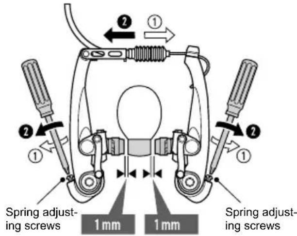
Adjusting the brakes on the rim
Worn brake pads
The rubber brakes for brake pads are almost all made with grooves and notches.
The grooves and notches help recognize when the rubber brakes have been subject to too much wear and tear. If the grooves and notches aren't visible anymore, then you must replace the rub - ber brakes.
What to do if the rubber brakes start rubbing against the rim:
You can use the spring adjusting screws to adjust the rear spring force in such a way that both rub - ber brakes lift from the rim the same way whenever you let go of the brake lever. Finally, make sure that the brakes are working properly (see chapter "Adjusting the brakes").
Brake blocks/pads and rims are wearing parts due to their use. Have the state of wear inspected at regular intervals by your FLYER specialist retailer.
Grooves in the brake blocks and embedded points in the rims help you determine the level of wear.
The brake blocks or rims must be changed when these grooves or points are no longer visible. Al - ways change both brake blocks at the same time.
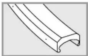
natural_image
Pure technical line drawing of a curved mechanical component (no text or symbols)New rim (with points to indicate wear)
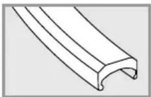
natural_image
Pure technical line drawing of a curved mechanical component (no text or symbols)Worn rims
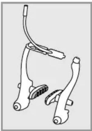
natural_image
Line drawing of a bicycle brake system with two suspension components (no text or symbols)New brake pads Worn out brake pads
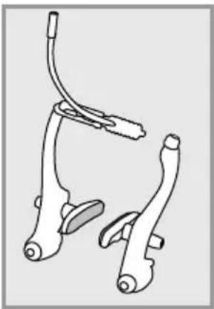
natural_image
Line drawing of two bicycle levers with attached straps (no text or symbols)Hydraulic rim brakes
Although hydraulic rim brakes require relatively little maintenance, they need to be regularly looked at and eventually readjusted.
Due to the wear and tear put on the brake pads, the brake levers will eventually need to be pushed down harder to operate. When this happens, you may have to adjust the rim brakes. As is the case for most bike models, this can be done by adjusting a screw or a setting wheel on the brake lever. Ask your FLYER specialist retailer for details.
Hydraulic rim brakes
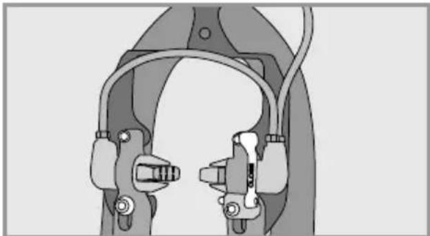
natural_image
Technical illustration of a mechanical clamp or bracket assembly (no text or symbols visible)To remove the front or rear wheel, you must first open the quick release lever on the brakes. To do this, pull the lever downwards until writing "OPEN" is read. Now remove the loosened brake unit from the brake bosses by removing it pulling it out from your seat. You should now have enough room to dismount the wheel.
Attaching a new wheel required following this procedure in reversed order. Before closing the brakes' quick releases, the brake must be positioned in such a way that the rubber brake pads touch the middle of the rim when the brakes are in use. Make sure that on the quick release lever on the brakes show the writing "CLOSED".

You should at least perform a brake test before taking the bike on public roads again.

Check periodically the brake pads and let your retailer replace them when they are too worn.
You can find further information in the manufacturer's manual or online under www.magura.com

Let a retailer check your e-bike if the brakes aren't functioning properly. If the rubber brake pads are too worn to be readjusted, do not use your e-bike any - more. Let your retailer to replace them with new brake pads before riding again.
Disc brake

Disc brakes must be installed and serviced by a FLYER specialist retailer. Incorrectly set up brakes can cause accidents and serious injuries.
A brake test is required before each drive and particularly after each brake adjustment. Braking behaviour may vary, in particular after exchanging the brake pads. Disc brakes require a bedding-in time to wear in the discs and pads. The braking system only delivers its full performance after around 10 braking cycles from 30 km/h. The braking force increases during this time. Consider this during the entire duration of the wearing-in period. This wearing-in period is also required after replacing the brake pads or discs.
Pay attention to any unusual noise when braking, as this could be a sign that the brake pads have worn down to the wear limit. Check the thickness of the brake pads once the brakes have cooled down. If necessary, have the brake pads replaced.

Please do not touch the brake disc while it is rotating. You can suffer serious injuries if your finger is caught in the gaps of a rotating disc brake.
The brake calliper and disc may get hot during braking. You could suffer burns if you touch this part during or directly after braking.
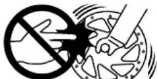
Source: Shimano® techdocs
Have the brake disc replaced if it is worn out or bent. This replacement procedure must be carried out by a FLYER specialist retailer.
Hydraulic brakes
It is possible that brake fluid may escape from the system due to leaky cables and connections.
This can negatively impact the effectiveness of the brakes. Check the pipes and connections for tightness before each ride.
Do not ride with your FLYER if fluid is leaking from the braking system. Allow a FLYER specialist retailer to undertake repair work on this part immediately. The danger of your brakes failing in this condition is very high.

Formation of air bubbles in the disk brakes
You can avoid this problem by applying the brake lever before transport and then fixing it in this position using a strap.
This prevents any air from entering the hydraulic system. Please note that the brake lever may not be pulled when the wheel has been removed. Place a spacer between the brake blocks if you need to remove the wheel.
Ask for detailed instructions regarding the operation and special features of the e-bike braking system from your FLYER specialist retailer, even if you are an experienced cyclist. Practise in a quiet, safe area with no traffic.
If you have any questions about assembling, setting up, servicing or operating this part of your bike, please contact a FLYER specialist retailer.

A trigger point should be clearly noticeable after approximately a third of the way when pulling the brake lever. Do not start to ride if the brake lever can be pulled up to the handlebars. In this case, the FLYER is not safe for operation. It is then essential to visit your FLYER specialist retailer and have the brake adjusted or repaired.

Brake discs and brake pads are particularly subject to wear. Have these safety-related components regularly checked for wear and changed as required by your FLYER specialist retailer.
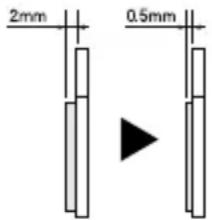


Source: Shimano® techdocs
If the brake system needs to be cleaned, contact your FLYER specialist retailer. The component manufacturer's instructions on how to clean the brake system are provided in the respective brake system manual.
Only allow your FLYER specialist retailer to maintain the brake system and change individual brake system components. Only original spare parts may be used. Otherwise it is possible that the functionality of your FLYER e-bike may be impacted or damaged.
Have the brake pads regularly checked according to manufacturer specifications by your FLYER specialist retailer.

It is essential to switch off the electrical operating system and remove the battery before any form of maintenance work is carried out.
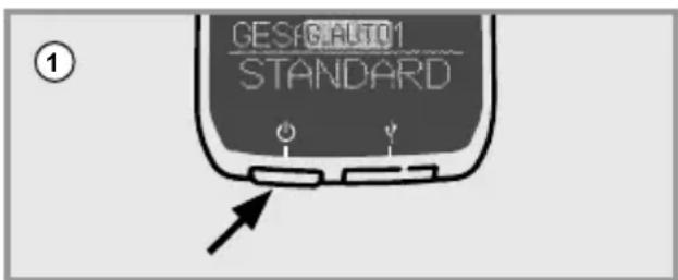
Switch off the operating system
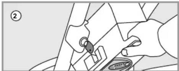
natural_image
Illustration of hands using a tool to adjust or install a component, no text or symbols visibleRemoving the battery
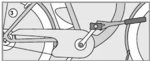
natural_image
Mechanical linkage diagram showing a lever and chain assembly (no text or labels)Performing maintenance work

Maintenance work on the brakes must be undertaken by a FLYER specialist. Liquids containing oil may never be applied to brake pads, brake surfaces of the rim, brake blocks or brake discs. These substances reduce the effectiveness of the brakes.
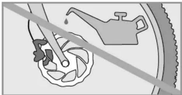
natural_image
Diagram showing a hand holding a tool near a car wheel, with a faucet and tire in the background (no text or symbols)
Do not drive when brake pads, brake blocks, brake discs or rims are polluted with lubricant. Dirty pads and blocks must be replaced and dirty rims and brake discs must be cleaned.

Only original spare parts may be used when changing the brakes.
16. Lighting system
Your FLYER e-bike's lighting system is usually powered by the battery. When the battery is empty, the light should still work for about one hour. The headlight must be aligned to illuminate the road according to the legal regulations of your country.

If necessary, have the lighting system checked and changed by your specialist retailer when you discover faults in its function.
Some models are equipped with daytime driving lights. These are supplied by various energy sources depending on the riding situation.

Clean your reflectors and lights on a regular basis. Warm water with cleaning fluid or washing up liquid is suitable here.

The lighting system is key and it is vital that it is proper working condition. Only allow authorised FLYER specialist retailers to perform checks and servicing work after failures or temporary problems!
17. Riding with additional load
Luggage carrier /riding with luggage
Transporting baggage changes the riding performance of your FLYER e-bike. Not only is the braking distance lengthened with more weight, the steering is also less responsive. You should therefore adjust your riding style to the braking and steering behaviour of your FLYER, and always anticipate a longer braking distance. Only transport luggage on the approved luggage racks and ensure that the maximum permitted overall weight as well as the maximum load capacity of the luggage rack are not exceeded. These values may never be exceeded. Don't fix racks at the seat post; This can lead to breakages and to very serious falls. The manufacturer's warranty will also expire in this case.

Make sure that your luggage is firmly and safely attached when transporting packing bags or other loads. Ensure that no parts can get hooked in the spokes or the turning wheels.
18. Mudguard
The mudguard is fitted with a safety fastening in case an object jams between the mudguard and the tyre. This releases the mudguard from its holder to prevent a fall.
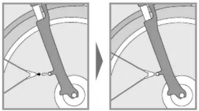
natural_image
Diagram showing a mechanical linkage or wheel assembly before and after, with no visible text or symbols.You must stop riding immediately if a foreign body is trapped between the tyre and the mudguard. Remove the foreign object before beginning to riding again. Otherwise, there is a risk of a fall and serious injuries.

You may under no circumstances drive with a loose mudguard strut, as the strut may jam in the wheel and block it. The loose ends of the holders may lead to serious accidents.
Damaged mudguards must be replaced by a FLYER specialist retailer before riding again. You should also regularly check whether the braces are fixed securely in the safety releases.
19. Accessories and equipment
Appropriate installation of accessories and checking their compatibility with the FLYER are the responsibility of the cyclist/buyer. Only accessories listed in the FLYER catalogue are approved for use with the FLYER by Biketec AG. Check the relevant accessories for compatibility with your FLYER model and consider their technical specifications (e.g. maximum load, installation instructions, etc.).

Always install accessories according to the regulations and instructions.
- Only use add-on parts that comply with the respective legal regulations and road traffic regulations.
- The use of unauthorised accessories may lead to accidents, severe falls and damage. You should therefore only use original accessories and add-on parts which fit your FLYER.
The warranty and/ or guarantee can become void if unapproved accessories are used.
Biketec AG cannot be held liable in connection with the use of unauthorised accessories.

The installation of accessories might damage the paint work.

The frame, battery or components may not be changed and no holes may be drilled into them in order to attach accessories.
19.1 Transporting children/child seats

The safe transport of children is the responsibility of the cyclist. Biketec AG cannot be held liable in connection with the transport of children and the resulting risks.
The use of child seats is only approved by the manufacturer for the following luggage racks:
Pletscher Genius Plus with 3-point sys - tem in combination with the associated Pletscher child seat.
The use of child seats is not approved for any other luggage racks offered.
19.2 Bicycle trailers and child trailers
The safe transport of children is the responsibility of the cyclist. Biketec AG cannot be held liable in connection with the transport of children and the resulting risks.

Please inform yourself of the applicable national guidelines before you use a trailer, especially when transporting children. Only use trailers which satisfy the requirements of the applicable national legal guidelines. The use of a trailer may lead to severe falls and injuries.

It is not permitted to use a fast e-bike to transport children in a child trailer in Germany.
Ensure additional safety when riding with a child trailer. Use clearly visible, colourful flags and additional lighting elements. Only use tested and licensed trailers and safety equipment.

- The handling of the FLYER e-bike is negatively influenced by using a trailer. You should therefore adjust your riding style accordingly. Otherwise there is a danger that the trailer could flip over or come off, which could lead to very serious falls and accidents.
- Bike trailers will significantly extend the overall length of your FLYER. Practise setting off, braking, riding around corners and on hills in a safe place with an empty trailer.
- The maximum permitted overall weight of the vehicle also includes the weight of the trailer and any other load.
- You may require a substantially longer braking distance to stop when riding with a trailer. Please take this into account in order to avoid accidents.
- Ask your FLYER specialist retailer about the maximum permitted weight of the trailer you may tow with your FLYER.
- Ask your FLYER specialist retailer about the correct selection and installation of the trailer coupling.
19.3 Roof and rear carrier on a car

- Only use rear carriers which satisfy the applicable national legislation for transporting your bike by car. The use of rear carriers may lead to accidents.
- Adjust your driving according to the weight of your rear carrier.
- In the case that you attach a trailer to the bike, make sure to regularly check if it is securely fastened to the FLYER e-bike. If your FLYER falls out of the carrier, it can cause serious accidents.
- Avoid transporting your FLYER on the roof of a vehicle and always cover the motor with a rain protector cover to prevent it from becoming damaged. It is recommended to cover the entire FLYER e-bike with a rain protection cover.
- Please note that loose parts, such as tools, luggage and tool bags, child seats, air pumps etc. could fall off during transport. This may put other people on the road at risk. All loose parts should therefore be removed from the FLYER before you start riding.
- A roof rack changes the total height of your vehicle.
- Also make note of the maximal load capacity for the roof of the vehicle.

The brake lever may not be used when your bicycle is lying sideways, upside down or if a wheel has been removed. Otherwise air bubbles can enter the hydraulic system which could cause the brakes to fail. After transporting the bicycle, check if the pressure point of the brakes seems softer than before. Then apply the brakes slowly several times. This allows the braking system to discharge any bubbles. If the pressure point remains soft, please refrain from riding. A FLYER specialist retailer must discharge the air from the brake system.

You can avoid this problem by applying the brake lever before transport and then fixing it in this position using a strap. This prevents any air from entering the hydraulic system. Please note that the brake lever may not be pulled when the wheel has been removed. Place a spacer between the brake blocks if you need to remove the wheel.
The driver is responsible for transport by car in compliance with the applicable laws and regulations. Biketec AG cannot be held liable in connection with the transportation of the FLYER on roof or rear carriers.

- Do not transport your e-bike upside down. When securing the bike, ensure that no damage is caused to the fork or the frame.
- You may not attach your e-bike to the roof rack or rear carrier by its crank set. The e-bike must always be transported standing on its wheels. Non-compliance may result in damage to the e-bike.
- When transporting the e-bike by car, the battery must be removed and transported separately. Make sure that the battery contacts are safe from short circuiting.
Public transport
Obtain information regarding the local regulations when you intend to transport your e-bike on public transportation.
Aircraft
Obtain information regarding the legal guidelines if you intend to transport your FLYER by aircraft. Ask your airline.
20. Bike folding instructions FLYER Pluto
These folding instructions contain important information needed to know how to fold your new FLYER. They also provide you with safety tips and help you prevent harming people, objects and the environment. You should therefore keep this manual in a safe place, always have it to hand and observe the pointers provided in this manual which have proven to be helpful when using this FLYER. Please provide these instructions with the FLYER when you lend your FLYER to other persons.

Always make sure that your FLYER Pluto is in a safe position when transported in a folded state. Especially when transporting your bike by public transportation or car, you should make sure it won't fall when the vehicle is in motion. You may need to secure it better or firmly hold unto it. If your bike falls over, important components may become damaged.

You may only maintain, work on the bike, etc. when the system is switched off.
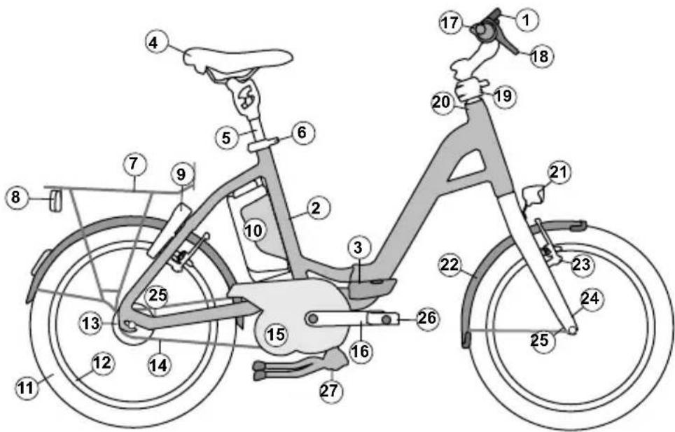
① Display
② Frame
③ Folding hinge with safety lever
④ Seat
⑤ Seat post
⑥ Quick release lever on the seat post
⑦ Rack
⑧ Rear light
⑨ Frame lock
⑩ Battery
⑪ Wheel
12 Rim
⑬ Hub
⑭ Chain
⑮ Motor (under the chain guard)
⑯ Crank
⑰ Handlebars
18 Brake levers
⑲ Stem (Speedlifter Twist)
20 Headset
21 Headlights
22 Mudguard
23 Brake
24 Fork
25 Securing the bike in a folded state
26 Folding pedals
27 Bike stand
20.1 Using quick releases
Quick releases are systems installed on the bicycle in place of bolted connections. They consist of two parts: the clamping lever, which provides the necessary clamping force, and the locking nut, which allows you to regulate the clamping force. You can change the setup of your quick release when the clamping lever is open.
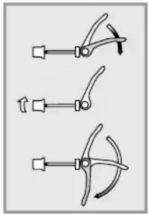
natural_image
Three mechanical clamping tools with lever mechanisms, shown in different orientations (no text or symbols)Loosening the Adjusting Nut

natural_image
Three diagrams showing a tool with curved blades and arrows indicating motion (no text or symbols)Tightening the Adjusting Nut

You will know if the quick release and locking lever have been closed with the proper gripping force when you feel pressure half way through closing them. Just before it closes, you should have to apply extra force with the ball of your thumb to close the lever completely.

- All quick release skewers must be firmly closed before you set off.
- Check all quick release fasteners for correct attachment if the vehicle was parked for a short time without supervision and before every ride.
- A closed quick release fastener must be folded close to the frame, fork or seat post.

In addition to closing the folding bike, you should also lock up the bike with a separate locking device, i.e. with a cable lock. By doing so, you will prevent your bike from being stolen.
20.2 Adjusting and readjusting the frame's folding hinge

After 500 folds or when the gripping force decreases, let your FLYER retailer check the gripping force on the folding hinge.

Proper gripping force of the folding hinge: 10kg/98.1N
20.3 Folding instructions for the FLYER Pluto

The riding system must always be switched off before beginning the folding procedures.
To make it easier and safer to fold your FLYER Pluto, the bike has been equipped with quick release fasteners in all the places most important.
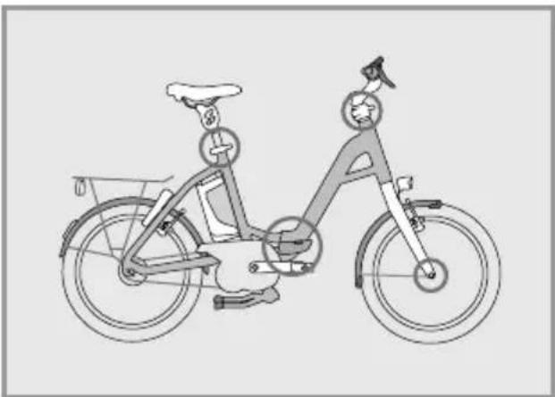
natural_image
Line drawing of a person riding a bicycle with a bicycle wheel and basket (no text or symbols)
Before beginning to fold the bike, remove the key from the battery and bike lock.

Fold up the bike stand on your FLYER Pluto in such a way that it won't fall unto the motor.

Before the folding process place the crank horizontally or turn the left pedal downwards and leave it in this position.
- First fold the pedals of your FLYER Pluto. Press the pedals towards the crank (1) and turn them down 90° (2).
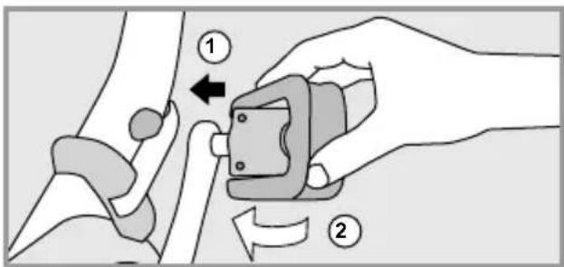
- Stand on the left side of the bike. Open the quick release (1) and press the seat post all the way down (2).
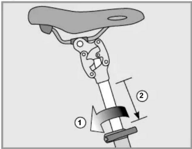
Close the quick release again (3) to keep the saddle in this position.
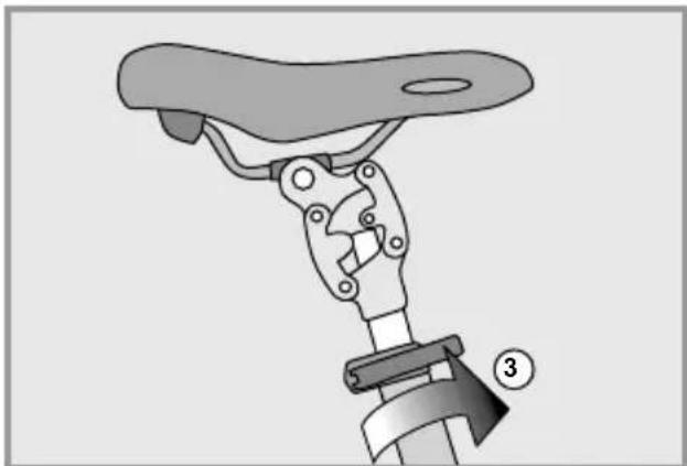
natural_image
Mechanical assembly diagram showing a lever mechanism with a numbered component (no text or symbols present)- Open the quick release lever (1) on the Speedlifter.
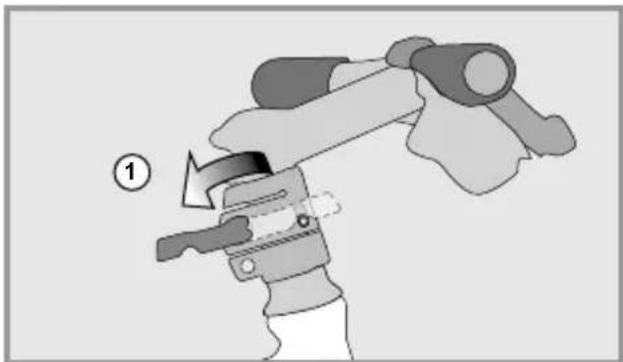
natural_image
Illustration of a mechanical device with a numbered label (1) indicating a step, showing a lever mechanism without any text or symbols.Lift the unlocking bolt (2).

natural_image
Illustration of a hand using a tool to adjust or install a mechanical component, with no visible text or symbols.This should not enable you to turn the handlebars to the right (3). The bolt automatically latches in the 90-degree positon (4). Completely close the quick release lever so that the handlebars are safely fastened.
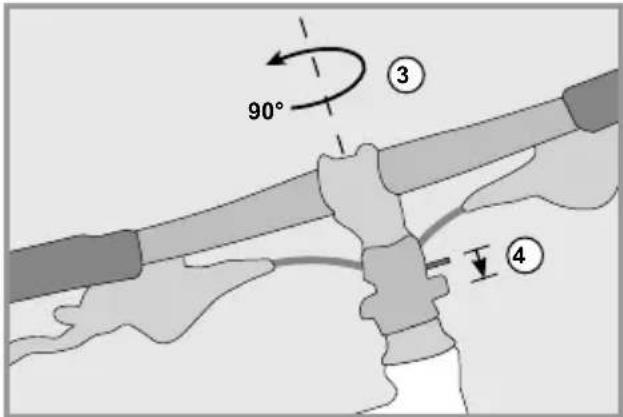
- First open the safety lock of the frame hinge by pushing the button in the middle of the lever (1). Finally fold the lever outwards (2).
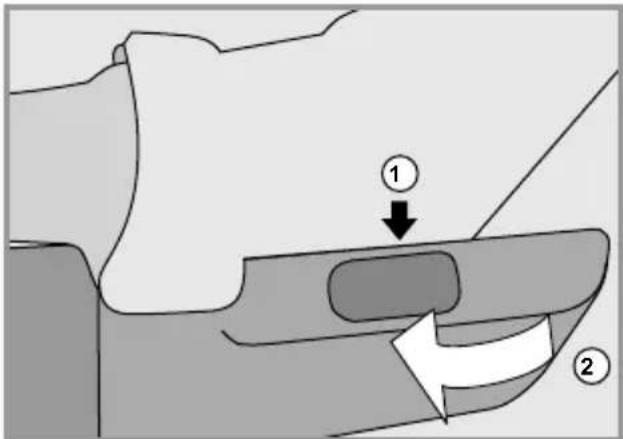
You should now be able to fold the front part of the frame to the left (3).
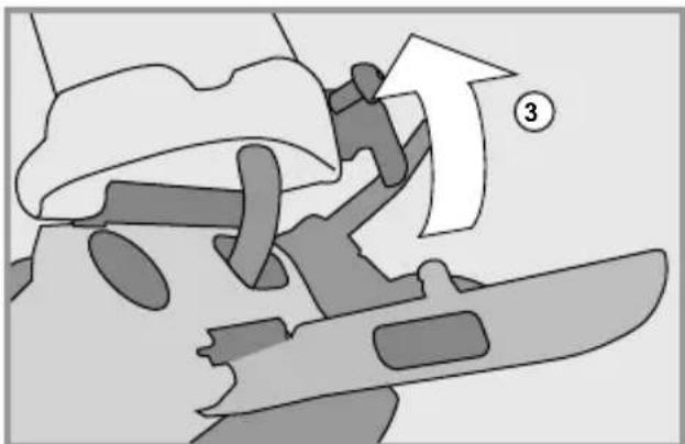
natural_image
Diagram showing a person climbing a slope with an arrow and number 3, no readable text or symbols present.- Fold the front and rear part of the frame towards each other until the brackets on the fork are able to attach to the chainstay.
To secure the bike correctly in its folded state, follow the instructions entitled "Folding and securing the FLYER Pluto".

Make sure that the frame between the front of the fork and the left side of the chainstay is completely locked in place. If it isn't, this can cause the folding bike to fold open when picked up and may cause injury.
- If folded correctly, your FLYER should look like this:
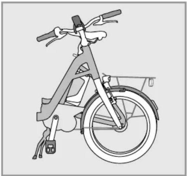
natural_image
Line drawing of a bicycle with front wheel, rear wheels, and side-mounted sensors (no text or symbols)Fold up the middle bike stand again before transporting the bike.
20.4 Unfolding the FLYER Pluto
Before you begin unfolding your FLYER Pluto, fold down the middle bike stand and either begin to position the cranks horizontally or bring the left crank all the way down.
- Release the folding clasps by pulling the bolt on the fork out of its slot which is located on the rear frame.
- Pull the front and back part of frame apart until they are in a straight line and can no longer move. The folding joint locks once the bolt automatically falls into its slot.
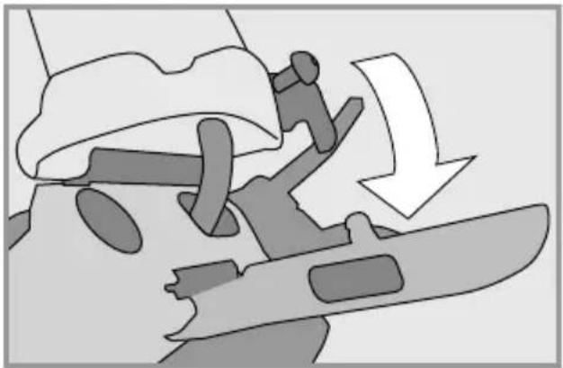
natural_image
Diagram showing a mechanical assembly with a downward arrow and a tool, no text or symbols present- Fold the sealing lever forwards (1). Close the lever on the folding joint with the ball of your thumb until you hear it latch and fall into the highest position.
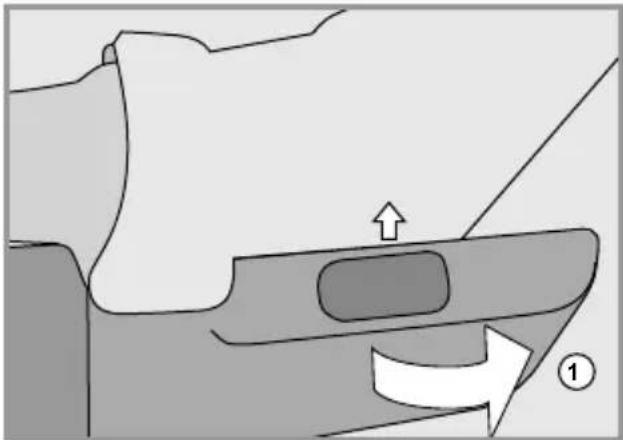
natural_image
Diagram of a mechanical component with an arrow indicating direction, no text or symbols present
Make sure that there is enough gripping force. If there isn't enough gripping force, you will need to contact a FLYER retail shop as soon as possible and have the fastening lever replaced. Make sure that the lever is securely fastened.
When turning back the handles, open then Speedlifter: Lift the unlocking bolt (1).
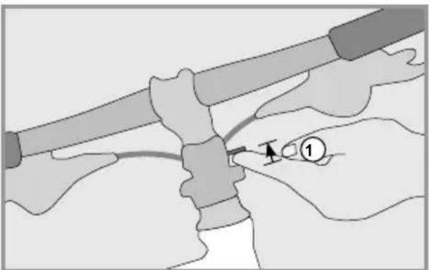
natural_image
Illustration of hands connecting a tool to a mechanical component, no text or symbols presentAfterwards, turn the handles 90^ to the left and back into the riding position (2). The bolt must be re-latched (3).
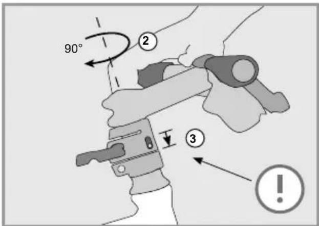
Now pull the front part of the bike upwards and to the height you prefer. (4). Notice the marking showing how far you can pull it upwards. The stem of the bike should not be pulled up further than this marking! Close the quick release (5) so that the handles stay in their position.
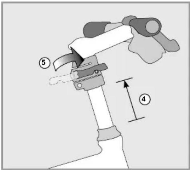
- Open the quick release to the seat post (1)
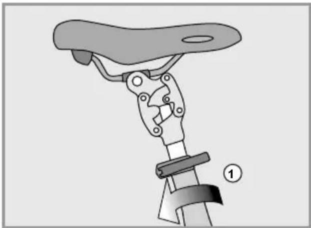
natural_image
Mechanical assembly diagram showing a lever mechanism with a numbered label (1) indicating a step or component, no text or symbols present.and pull it out from the saddle tube and to your desired height (2). Then correctly close the quick release again(3) so that the saddle stays in its position.
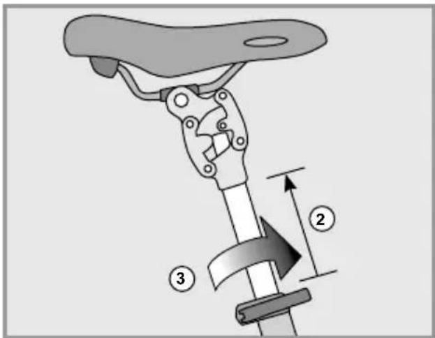

There are markings on the seat post which show how far it can be pulled out of the frame. Never pull the seat post beyond the maximum length marking.
- Now unfold the pedals to your FLYER Pluto. Fold them outwards 90° (1). Pull the pedals carefully outwards (2) until they latch into their riding position.
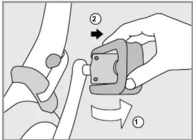

Make sure that all of the quick releases and fastening latches are correctly and securely fastened.

Before riding, fold in the middle bike stand again!

Before each ride, make sure there is enough gripping force to the folding hinge as shown in chapter 20.2. In addition, make sure that all the fuses are correctly closed. When riding, the folding hinge must always be secured and never altered.

Have your FLYER retailer regularly check the folding clasp. Do not turn the adjusting screws on your own.
21. Electrical motor
All information, data and instructions concerning the electrical system of your FLYER e-bike are included in the attached operating instructions for the electrical support system installed in your FLYER. They include details of the operation and maintenance, all important safety instructions and information concerning the following components:
- Operating element and display
- Battery and possible ranges
- Charger
- Drive unit
• Speed sensor and spoke magnet
Some general facts concerning the function and range of your FLYER's motor are listed below:
Function:
The motor starts working as soon as you start pedalling when one of the support modes has been selected.
The performance of the motor depends on several factors:
• The force used while pedalling
The support is more gentle when you pedal with low force than when you pedal with higher force, e.g. while driving uphill. However, this in creases the power consumption and decreases the range.
- Support mode
The higher the level of support, the more power the motor will provide. However, high motor performance means high power consumption.
The lowest support mode provides the least support but also the longest range.
Range
Specified range information has been obtained under optimal conditions. Ranges achieved under everyday conditions will usually be shorter. Please consider this when planning your route.
The range depends on many factors. These include battery capacity, motor support level selected, geographical conditions, road surface, driving style, environmental temperature, the weight of the driver, tyre pressure and the technical state of your FLYER e-bike.
Driving without drive support
You can also drive your FLYER without drive support by selecting the "No assist" support mode.
Ensure that your system is always switched on.

Never drive without a battery or with your system switched off, as the functions of the operating unit and the lighting functions are not available in this case.

Always remove the battery before cleaning, maintaining or repairing your e-bike. Ensure that you do not touch and thus possibly connect contacts when cleaning or maintaining the battery. You risk being hurt and the battery may suffer damage if the contacts are live.
Do not use a high pressure water stream or a high pressure cleaner on your bike. The cleaning liquid may enter sealed bearings due to high pressure, dilute the lubricant and increase friction. As a result, rust is formed which destroys the bearings. Cleaning with a high-pressure cleaner may damage the electrical system.

You should avoid doing the following when cleaning your FLYER e-bike:
- Acids
- Fats
• Oil - Brake cleaner (only to use on brake discs)
- Solvent-based liquids.
These damage the surfaces and contribute to wear on the FLYER.
After use, ensure that you dispose of the lubricant, cleaning and care products in an environmentally friendly way. These substances do not belong in domestic waste, in the drain or in natural environments.
Smooth operation and durability of your FLYER e-bike depend on appropriate maintenance and care for your FLYER.
- Regularly clean your FLYER with warm water, small amounts of cleaning agent and a sponge.
- While cleaning the FLYER, always check your e-bike for cracks, notches or material deformities.
- Damaged parts must be changed with original spare parts. Please only ride your FLYER again after this check has been carried out.
- Have possible paint damage removed by your FLYER specialist retailer.
Further important information concerning care for your FLYER e-bike is provided on the website of your respective component manufacturer.
22. Wearing parts
Your FLYER is a technical product and therefore requires regular inspection.
Many parts of your FLYER are subject to very rapid wear, depending on their function and the extent of usage.
This includes:
- Tyres
- Rims in connection with rim brakes
- Brake pads
- Brake discs
- Bicycle chain or drive belt
- Chain wheels, sprockets, jockey wheels
- Lighting system
- Handlebar grips
- Lubricants
• Gear and brake cables - Bearings
- Suspension elements

Have your FLYER regularly inspected in a FLYER specialised workshop and have wearing parts changed as required. Regular visual inspection for cracks, scratches and damage to components is the responsibility of the driver.

The bicycle is subject to wear and high stress as are all other mechanical components. Depending on the degree of stress imposed on them, different materials and parts may react differently in terms of wear and fatigue. A part may suddenly fail and cause injuries to the driver when its designed service life is exceeded. Any kind of cracks, scratches or colour changes in high-stress areas are an indicator that the service life of the component has been exceeded and that it should be replaced.
23. Inspection plan
After the first 200 ridden kilometres or after 4 months:
FLYER specialist retailer
- Check the firm attachment of all screws, nuts and quick release fasteners
- Check the wheels and centre them as required
- Check the tyres
- Check the fastening torque on all parts
- Adjust the headset
- Check the brake and shifter cables
- Check the gear system and adjust if necessary
- Check the brakes, adjust if necessary
- Check the suspension elements, adjust if necessary
- Sufficient lubrication of all components
- Checking the folding clasp (FLYER Pluto)
FLYER driver
During your e-bike's first inspection by the FLYER specialist retailer, ask them to explain the correct processes for clean - ing and oiling the chain after rain and checking components for function or damage.
Before each ride – FLYER driver
- Check the correct position of the bell
- Check the function of the brakes
- Check the function of the gear system
- Check the function and correct setting of sus - pension elements
- Are all quick release fasteners, quick release axles, screws and nuts completely closed and fastened?
- Check that the tyre pressure is correct
- Check the wheels for true running and damage as well as safe attachment and correct fastening
- Check that the handlebars, stem, seat post and seat are safely attached and correctly positioned
- Check the battery's charge status
- Check that the battery is correctly and securely attached.
- Checking the folding clasp (FLYER Pluto)
After each ride – FLYER driver
• Cleaning the FLYER e-bike
- Visual inspection of the frame and of components for cracks and damage
- Check the tyres for damage, wear, brittleness, alien objects and sufficient profile depth
- Check the rims for wear and true running
- Check the tension of the spokes
- Clean the chain and sprockets as required and lubricate them with a suitable chain oil approved by the manufacturer
- If necessary, clean the brake discs with a suitable brake cleaner approved by the manufacturer
- Clean all bearings as required and lubricate them with suitable lubricant approved by the manufacturer
- Clean suspension elements as required and lubricate them with original lubricant approved by the suspension manufacturer
- Clean all moving parts for which lubrication is intended (especially quick release fasteners, quick release axles and the joints) as required and lubricate them with a suitable lubricant approved by the manufacturer
Allow your FLYER specialist retailer to instruct you.
What to do after riding in rain, snow or wet conditions:
(in addition to the points under "After each ride")
FLYER driver
- Clean the chain and lubricate it with a suitable lubricant approved by the manufacturer
- Clean the brake
- Clean the gear system
- Check the sufficient lubrication of all components
Allow your FLYER specialist retailer to instruct you.
Monthly – FLYER driver
Check that all screws, nuts, quick release axles and quick release fasteners are firmly attached
Every year or after every 1000 km, whichever occurs first
FLYER specialist retailer
- Lubrication of all moving parts for which lubrication is intended (excluding brake surfaces)
- Visual inspection of the frame and of components for cracks and damage
- Mend paint damage
- Replace parts with rust spots
- Treat all bare metal parts (excluding brake surfaces) against corrosion (rust)
- Change defective or damaged parts
-
Check the wheels and centre them as required
-
Check the tension of the spokes
- Check and clean the chain/sprocket/cogset
- Lubricate the chain with a suitable lubricant
- Check the rim for wear
- Check the brake pads for wear
- Check that all screws, nuts, quick release axles and quick release fasteners are firmly attached
- Check the brake system and quick release ax - les and adjust it or replace parts if necessary
- Check the gear system and adjust or replace parts of it if necessary
- Check the hubs
- Check the headset
- Check the pedals

Only use cleaning agents and lubricants that are recommended or approved by the component manufacturer.

Please note that not all lubricants and care products are suitable for your FLYER. By using unsuitable lubricants or care products, you can damage or impact the functionality of your FLYER e-bike.

Ensure that the brake pads, brake discs and brake surfaces are not exposed to cleaning or servicing fluids or oils, as this reduces the performance of the brakes.
23.1 Maintenance work and exchange of wearing parts

Components to be changed may only be replaced with identical, original parts. Wearing parts may only be replaced with identical, original components.

Using any parts other than the original ones will immediately cause the manufacturer's liability for material defects and/ or the manufacturer's warranty service to become void. There is also an
24. General warranty
1. Retailer's Warranty
As in most cases, the warranty agreement will be upheld by the FLYER retailer for two years after the point of purchase.
After two years, assuming that the battery has been used and charged as informed in the instructions manual, it should still have a capacity level of 60% of its original level.
The normal wear of wearing parts (e.g. tyres, tubes, chains, sprockets, brake pads, paint, la bels) is not subject to warranty claims. The buyer is responsible for regularly maintaining and caring for the FLYER e-bike (i.e. having the bike inspected as suggested in the instruction manual). The warranty conditions will become void if you modify or repair the FLYER e-bike on your own. The same applies if you exceed the bike's limit of use by:
- Riding it in races and competitions
- Riding it for commercial uses
• Overcharging the battery
• Using it for other unintended purposes
2. Manufacturer's Guarantee for the Biketec AG a. Warranty Services
Despite the FLYER retailer's right of warranty, the Biketec AG will cover all warranty services when the FLYER e-bike needs to be completely remounted. In this case, the bike will be mounted and tuned by a FLYER retailer recognized by the Biketec AG. Starting at the point of purchase, the warranty will begin covering the following:
Frames: a 10 year warranty for broken frames; motor, motor control unit, display, charger: standard warranty of 5 years for factory and material defects; a 3 year warranty applies for "Mountain" FLYER e-bikes with factory and material defects.
For second-hand bikes, the warranty is activated on the same day it is registered.
b. Handling Warranty Claims
During the product's time of warranty, Biketec AG will cover all repair costs or replacements when the product has one of the defects listed above. For this to occur, however, a FLYER retailer, that is also recognized by Biketec AG, must clearly identify the FLYER e-bike's defect(s). You will also need to provide a valid proof of purchase (i.e. re-
ceipt, a filled-out e-bike pass). The warranty still applies when the purchase is passed on to a third party. Biketec AG reserves the right to deliver or install equivalent products when exchanging a FLYER or components as part of warranty claims.
Claims made under this warranty do not extend the original period. In this case, the same warranty restrictions apply that were listed under point 1.
25. Environmental protection tips
Please take the environment into account when caring for, cleaning or disposing of your FLYER e-bike. Use biologically degradable cleaning agents for maintenance and cleaning where possible and ensure that cleaning agents are not washed into the drain.
The complete vehicle, all components, lubrication and cleaning agents and particularly the battery
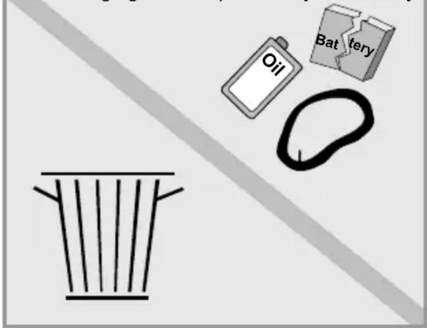
FLYER

flyer-bikes.com/manuals

natural_image
Two-step diagram showing hand positioning of a mechanical device, no text or symbols presentAccu opladen
natural_image
Abstract pattern of white star shapes with gray rounded rectangles inside (no text or symbols)natural_image
Line drawing of a car interior showing hands adjusting a bicycle seatbelt (no text or symbols)
natural_image
Illustration showing a hand using a tool to lift a bicycle, and the foot pressing a cable (no text or symbols present)
natural_image
Cross-sectional diagram of a mechanical component (no text or symbols)
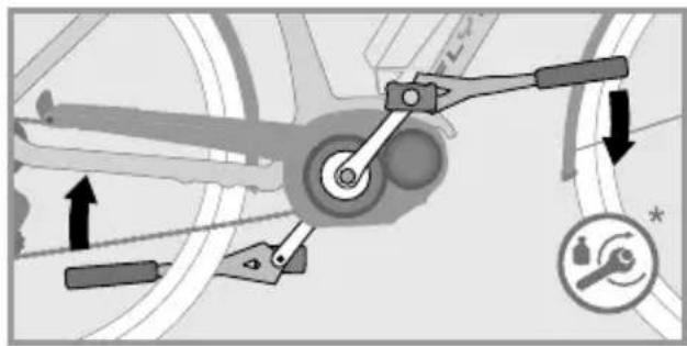
natural_image
Mechanical linkage diagram showing lever mechanism and gear movement (no text or symbols)natural_image
Three diagrams showing different types of clamping tools or manipulator mechanisms (no text or symbols present)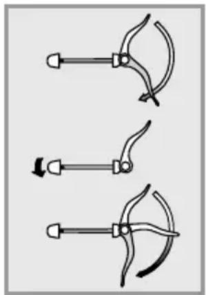
natural_image
Three diagrams showing a tool with curved blades and arrows indicating motion (no text or symbols)
natural_image
Close-up of a mechanical device with two circular button symbols (X and ✓) highlighted, no readable text or labels present.natural_image
Close-up of hands using a bicycle wheelbelt to adjust the wheel rim (no text or symbols visible)natural_image
Close-up of a hand adjusting a mechanical component with an arrow and plus symbol (no readable text or symbols)natural_image
Close-up of a bicycle wheel assembly with a white component and a circular arrow indicating rotation (no text or symbols)Demontage
natural_image
Close-up of a bicycle wheel assembly with a hand adjusting a component, showing no text or symbols.natural_image
Close-up of a hand adjusting a mechanical component with a white arrow pointing to it (no visible text or symbols)natural_image
Close-up of a hand adjusting a mechanical component with an arrow indicating rotational motion (no text or symbols visible)4. As uittrekken.

natural_image
Close-up of a hand adjusting a bicycle wheel component with a tool (no visible text or symbols)natural_image
Silhouette of a person riding a bicycle with 90-degree angles marked on the side (no text or symbols present)Hoek arm-bovenlichaam 90°
natural_image
Mechanical assembly diagram showing a lever mechanism with no visible text or symbolsnatural_image
Illustration of a hand holding a mechanical device with a numbered label (1) indicating step 1, no text or symbols present.natural_image
Illustration of a mechanical assembly with a hand holding a tool, showing a step and angle (no text or symbols)natural_image
Illustration of hands performing a medical procedure with a tool and arrow (no text or symbols)natural_image
Illustration of a robotic arm with a curved tool and labeled step 4 (no text or symbols on the diagram itself)
natural_image
Mechanical assembly diagram showing a lever mechanism with mounting base and housing (no text or symbols)Verstelbare stuurpennen
natural_image
Diagram of a manual tool with handle and lever mechanism (no text or symbols)natural_image
Illustration of a hand using a manual tool to lift a bicycle wheel (no text or symbols)Bron: Shimano ^® techdocs
natural_image
3D illustration of a threaded mechanical component labeled 'Autoventiel' (no other text or symbols)3. Buiten- en binnenbanden demonteren
natural_image
Diagram of a curved pipe or wheel with two vertical segments, no text or symbols present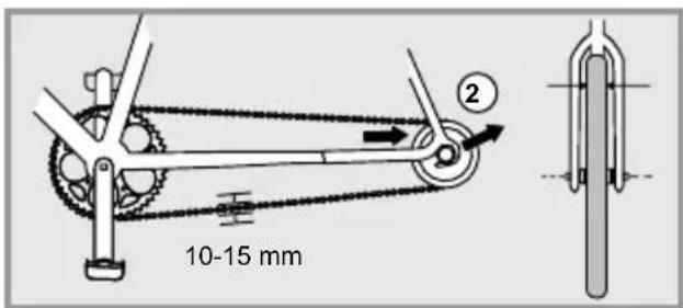
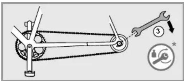

natural_image
Mechanical gear mechanism diagram showing interlocking gears and linkages (no text or symbols)natural_image
Mechanical gear mechanism diagram showing interlocking gears and chains (no text or symbols)natural_image
Mechanical gear mechanism diagram showing interlocking gears and a tool (no text or symbols)Bron: Shimano® techdocs

natural_image
Diagram of a manual tool with lever and handle, showing motion lines (no text or symbols)Achteruittraprem
natural_image
Technical line drawing of a curved metal bracket or support structure (no text or symbols)natural_image
Pure technical line drawing of a curved mechanical component (no text or symbols)versleten velgen
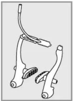
natural_image
Line drawing of a bicycle brake system with three levers and suspension components (no text or symbols)natural_image
Line drawing of bicycle frame components (no text or symbols)natural_image
Mechanical assembly diagram showing two clamping components with no visible text or symbolsBron: Shimano® techdocs
Bron: Shimano® techdocs
natural_image
Illustration of hands using a tool to adjust or install a component, no text or symbols visibleAccu verwijderen

natural_image
Mechanical linkage diagram showing a lever and chain assembly (no text or labels)natural_image
Diagram showing a hand holding a tool above a car wheel, with a faucet symbol above (no text or labels)
natural_image
Diagram showing a mechanical linkage system before and after assembly, with no visible text or symbols① Display
② Frame
③ Vouwscharnier met vergrendelingshendel
④ Zadel
⑤ Zadelpen
⑥ Zadelpensnelspanner
⑦ Bagagedrager
⑧ Achterlamp
⑨ Frameslot
⑩ Accu
⑪ Wiel
⑫ Velgen
⑬ Naaf
⑭ Ketting
natural_image
Three mechanical clamping or clamp tool illustrations showing different grip configurations (no text or symbols)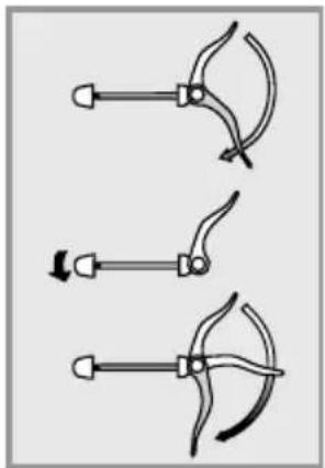
natural_image
Three diagrams showing a tool with curved blades and arrows indicating motion (no text or symbols)natural_image
Mechanical assembly diagram showing a lever mechanism with no visible text or symbols- Open de snelspanhendel (1) van de Speedlifter.

natural_image
Illustration of a mechanical device with a numbered label (1) indicating a step, showing a lever mechanism without any text or symbols.natural_image
Illustration of a hand holding a mechanical component with a numbered label (no text or symbols present)natural_image
Diagram showing a person climbing a slope with an arrow and number 3, no readable text or symbols present.natural_image
Line drawing of a bicycle with front wheel, rear wheels, and side-mounted sensors (no text or symbols)natural_image
Illustration of a person climbing a large aircraft with an arrow indicating downward motion (no text or symbols)natural_image
Diagram of a mechanical component with directional arrows indicating movement or force (no text or symbols)
natural_image
Illustration of hands connecting a mechanical component with a numbered callout (no text or symbols present)natural_image
Mechanical assembly diagram showing a lever mechanism with no visible text or symbols

FLYER EPAC (Electrically Power Assisted Cycle)
Typenbezeichnung
C SERIE, T SERIE, TX SERIE, U SERIE, FLOGO, PLUTO, UPROC, UPSTREET, GOTOUR
4950 Huttwil, Switzerland
Huttwil, März 2017

Andreas Kessler CEO
Ivica Durdevic CTO