
B 40010200 T - Compressor STANLEY - Free user manual and instructions
Find the device manual for free B 40010200 T STANLEY in PDF.
| Product Type | Piston Compressor |
| Brand | Stanley |
| Model | B40010200T |
| Power Supply | 230 V single-phase or 400 V three-phase (depending on version) |
| Maximum Pressure | 10 bar |
| Operating Pressure | 8 bar (running) / 10 bar (stop) |
| Recommended Oil Type | SAE 15W40 |
| Oil Change Interval | Every 300 service hours |
| Suction Filter Cleaning | Every 100 service hours |
| Safety Valve | Set to max tank pressure |
| Thermal Protection | Automatic cut-off in case of overheating |
| Usage | Compressed air for pneumatic tools, inflation, painting |
| Ambient Temperature | +5°C to +40°C |
Frequently Asked Questions - B 40010200 T STANLEY
User questions about B 40010200 T STANLEY
0 question about this device. Answer the ones you know or ask your own.
Ask a new question about this device
Download the instructions for your Compressor in PDF format for free! Find your manual B 40010200 T - STANLEY and take your electronic device back in hand. On this page are published all the documents necessary for the use of your device. B 40010200 T by STANLEY.
USER MANUAL B 40010200 T STANLEY
Belt Driven Compressor
Manufactured under license by:
Nu Air Compressors And Tools S.p.A. - via Einaudi 6, 10070 Robassomero (TO) Italy
Stanley® is a registered trademark of The Stanley Works or its affiliates and is used under license.
① Conservare questo manuale d'istruzioni per poterlo consultare in futuro
GB Preserve this handbook for future reference
F Conserver le présent manuel pour pouvoir le consulter ultérieurement
D Diese Bedienungsanleitung für späteres Nachschlagen sorgfältig aufbewahren
E Conservar este manual de instrucciones para poder consultarlo en el futuro
P Guardar este manual de instruções para o poder consultar no futuro
NL Bewaar deze handleiding voor toekomstige raadpleging
DK Opbevar denne brugsanvisning således, at det altid er muligt at indhente oplysninger på et senere tidspunkt
s Förvara denna bruksanvisning för framtida konsultation
FIN Säilytä ohjekirja voidaksesi etsiä siitä tarvittaessa ohjeita
GR Φυλάξτε το παρόν εγχειρίδιο οδηγιών για μελλοντική χρήση
PL Przechowywać niniejszy podręcznik instrukcji obsługi tak, aby można było korzystać z niego w przyszłości
HR Sačuvajte ovaj priručnik s uputama da biste ga mogli konzultirati u budućnosti
slo Skrbno shranite ta priročnik
H Örízze meg a kézikönyvet a jövőben való tanulmányozáshoz
CZ Uložte tuto příručku s pokyny pro použití na vhodném místě, abyste ji mohli kdykoli použít
SK Uschovajte túto príručku s pokynmi na obsluhu prístroja tak, aby ste mohli do nej kedykol'vek nahliadnúť
RUS Сохраняйте данное руководство в течение всего периода эксплуатации компрессора
N Du må oppbevare denne bruksanvisningen slik at du kan slå opp i den ved senere behov
TR Bu kullanım kılavuzunu gelecekte danışmak için muhafaza ediniz
RO Păstrați manualul de instructiuni pentru a-l putea citi și pe viitor
BG Запазете това ръководство по експлоатацията, за да можете да го използвате и в бъдеще
SRB Sačuvajte ovaj priručnik s uputstvima da bi mogli da ga konsultujete i u budućnosti
LT Saglabāt instrukciju rokasgrāmatu, lai varētu izmantot nepieciešamības gadījumā
EST Hoidke käesolevat kasutusjuhendit alles, et saaksite seda tulevikus kasutada
LV Išsaugoti šią instrukciju knygutę tam, kad ateityje galėtumėte joje pasikonsultuoti
I LEGENDA SEGNALETICA DI SICUREZZA SUI PRODOTTI
GB KEY TO PRODUCT SAFETY SIGNS
F LEGENDE DES PICTOGRAMMES DE SECURITE FIGURANT SUR LES PRODUITS
NL VERKLARING WAARSCHUWINGSSYMBOLEN OP PRODUCTEN
DK SIGNATURFORKLARING TIL PRODUKTERNES SIKKERHEDSSKILTNING
S FÖRKLARING TILL SÄKERHETSSYMBOLER PÅ PRODUKTERNA
GB Before use, read the handbook carefully
GB Warning, hot surfaces
GB Danger - automatic control (closed loop)
GB Hearing, sight and respiratory protection must be worn
natural_image
Close-up of a hand using a tire to measure a component, with a numbered label '3' pointing to the part (no text or symbols on the tire itself)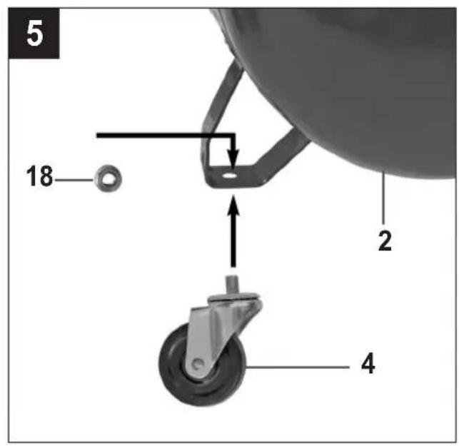
natural_image
Close-up of a hand adjusting a mechanical component with no visible text or symbols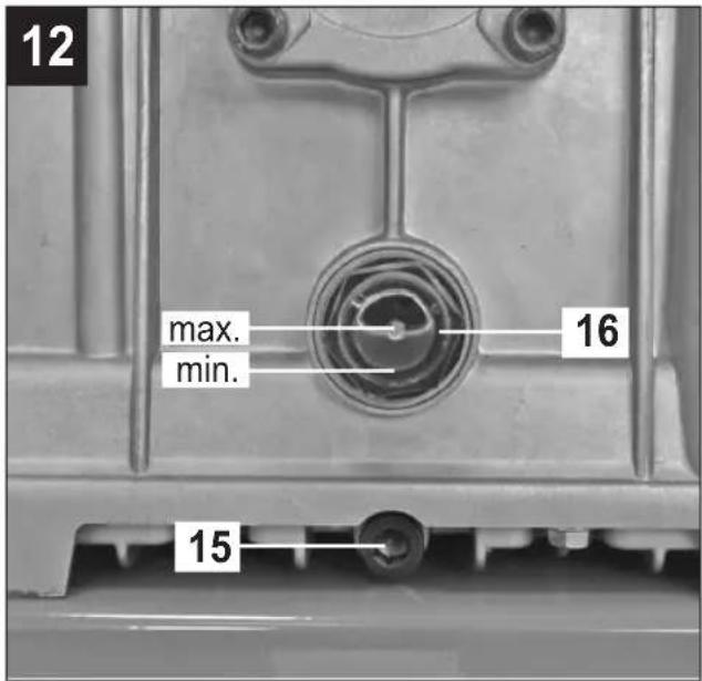
natural_image
Mechanical assembly diagram showing motor and gear components with a directional arrow (no text or symbols)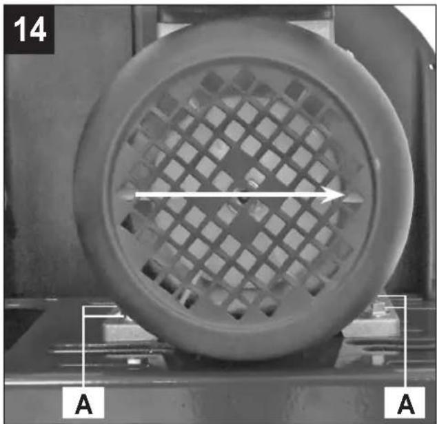
natural_image
Close-up of a circular perforated object with a grid pattern, mounted on a mechanical base (no visible text or symbols)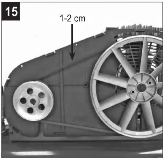
natural_image
Three black plastic electronic components with mounting holes and internal circuitry, connected by wires (no text or symbols visible)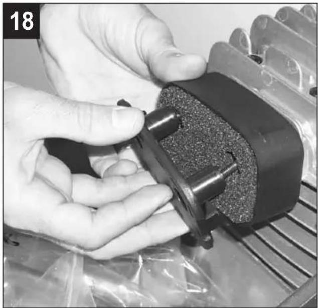
natural_image
Close-up of hands holding a black mechanical component with a textured surface, surrounded by plastic bags (no visible text or symbols)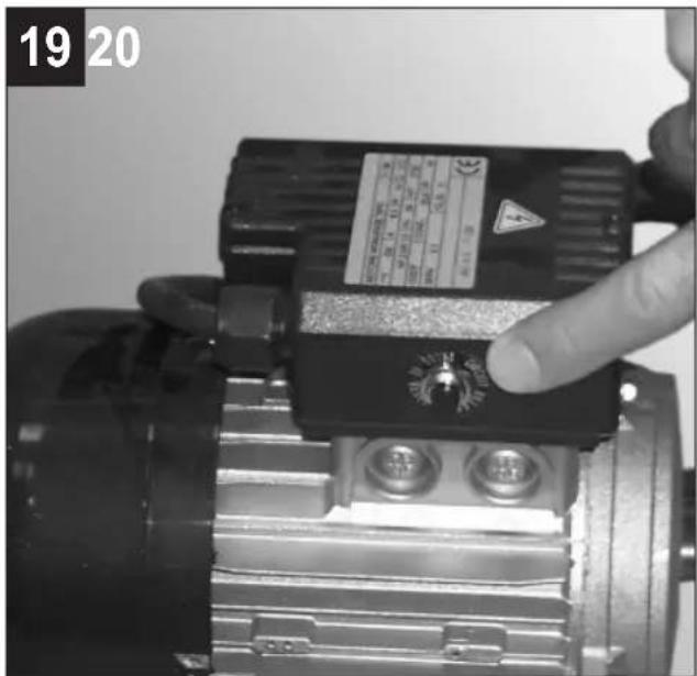
natural_image
Close-up of a hand adjusting a mechanical pipe fitting on a cylindrical tank (no visible text or symbols)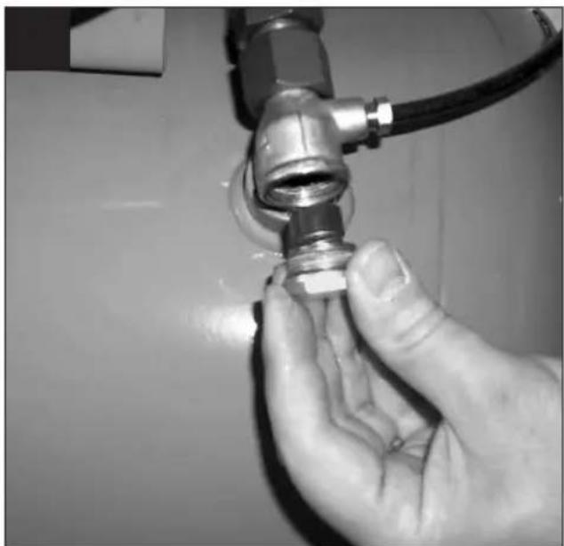
natural_image
Close-up of hands adjusting a metallic pipe fitting with a hose (no visible text or symbols)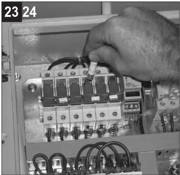
natural_image
Close-up of a hand installing or adjusting an electrical control panel with wires and components (no visible text or symbols)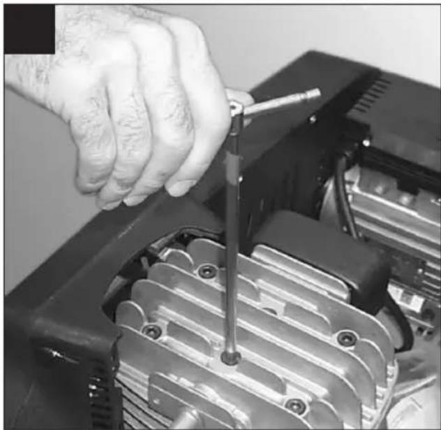
natural_image
Close-up of a hand using a screwdriver to adjust or install a car engine compartment (no visible text or symbols)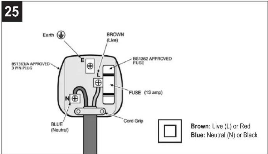
Preserve this handbook for future reference
1. PRECAUTIONS
An ACOUSTIC PRESSURE value of 4 m. corresponds to the ACOUSTIC POWER value stated on the yellow label located on the compressor, minus 20 dB.
▲ THINGS TO DO
- The compressor must be used in a suitable environment (well ventilated with an ambient temperature of between +5°C and +40°C) and never in places affected by dust, acids, vapors, explosive or flammable gases.
- Always maintain a safety distance of at least 4 meters between the compressor and the work area.
- Any coloring of the belt guards of the compressor during painting operations indicates that the distance is too short.
- Insert the plug of the electric cable in a socket of suitable shape, voltage and frequency complying with current regulations.
- For 3-phase versions, have the plug fitted qualified electrician according to local regular. When starting the compressor for the first time, check the correct direction of rotation and that this matches the direction indicated by the arrow on the belt guard (versions with plastic protection) or on the motor (versions with metal protection).
- Use extension cables with a maximum length of 5 meters and of suitable cross-section.
- The use of extension cables of different length and also of adapters and multiple sockets should be avoided.
- Always use the switch of the pressure switch to switch off the compressor or use the switch of the electric panel for models equipped with this. Never switch off the compressor by pulling out the plug in order to avoid restart with pressure in the head.
- Always use the handle to move the compressor.
- When operating, the compressor must be placed on a stable, horizontal surface to guarantee correct lubrication.
- Position the compressor at least 50 cm from the wall to permit optimal circulation of fresh air and to guarantee correct cooling.
▲ THINGS NOT TO DO
- Never direct the jet of air towards persons, animals or your body. (Always wear safety goggles to protect your eyes against flying objects that may be lifted by
the jet of air).
- Never direct the jet of liquids sprayed by tools connected to the compressor towards the compressor.
- Never use the appliance with bare feet or wet hands or feet.
- Never pull the power cable to disconnect the plug from the socket or to move the compressor.
- Never leave the appliance exposed to adverse weather conditions.
- Never transport the compressor with the receiver under pressure.
- Do not weld or machine the receiver. In the case of faults or rusting, replace the entire receiver.
- Never allow inexpert persons to use the compressor. Keep children and animals at a distance from the work area.
- This appliance is not intended for use by p (including children) with reduced physical, sensory or mental capabilities, or lack of experience and knowledge, unless they have been given supervision of instruction concerning the use of the appliance by a person responsible for their safety.
- Children should be supervised to ensure that they do not play with the appliance.
- Do not position flammable or nylon/fabric objects closed to and/or on the compressor.
- Never clean the compressor with flammable liquids or solvents. Check that you have unplugged the compressor and clean with a damp cloth only.
- The compressor must be used only for air compression. Do not use the compressor for a other type of gas.
- The compressed air produced by the compresso cannot not be used for pharmaceutical, food or medical purposes except after particular treatments and cannot be used to fill the air bottles of scuba divers.
- Never use the compressor without guards (belt guard) and never touch moving parts.
▲ THINGS YOU SHOULD KNOW
- To avoid overheating of the electric motor, this compressor is designed for intermittent operation as indicated on the technical dataplate (for example, S3-50 means 5 minutes ON, 5 minutes OFF). In the case of overheating, the thermal cutout of the motor trips, automatically cutting off the power
when the temperature is too high. The motor restarts automatically when normal temperature conditions are restored.
- To facilitate restart of the compressor, in addition to the operations indicated, it is important to return the button of the pressure switch to the OFF position and then to ON again (fig. 2).
- On single-phase versions, press the reset button on the terminal box of the motor (fig. 19).
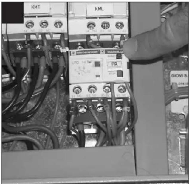
- On 3-phase versions, operate manually on the button of the pressure switch, returning this to the ON position, or press the button of the thermal cutout inside the box of the electric panel (figures 2b & 20).
- The single-phase versions are fitted with a pressure
switch equipped with a delayed closing air vent valve (or with a valve located on the check facilitates motor start-up; therefore a few-s jet of air from this, with the reservoir empty, is to be considered normal.
- To guarantee machine safety, all the are fitted with a safety valve that is activated in the case of failure of the pressure switch.
- When fitting a tool, the flow of air in output must be switched off.
- When using compressed air, you must know and comply with the safety precautions to be adopted for each type of application (inflation, pneumatic tools, painting, washing with water-based detergents only, etc.).

compress
2. LAYOUT
- Intake air filter
- Pressure vessel
- Wheel
- Guide roller (or supporting foot)
- Quick-lock coupling (regulated compressed air)
- Pressure gauge (for reading the preset tank pressure)
- Pressure regulator
- ON/OFF switch
- Transportation handle
- Safety valve
- Drainage screw for condensation water
- Pressure gauge (for reading the tank pressure)
- Quick-lock coupling (unregulated compressed air)
- Oil sealing plug (oil filler opening)
- Oil drainage screw
- Oil level window
- Bolt
- Nut
- Washer
- Check valve
3. SCOPE OF USE
The compressor is designed for generating pressed air for tools operated by compressed air.
Please note that our equipment has not been designed for use in commercial, trade or industrial applications. Our warranty will be voided if the machine is used in commercial, trade or industrial businesses or for equivalent purposes.
The machine is to be used only for its prescribed purpose. Any other use is deemed to be a case of misuse. The user / operator and not the manufacturer will be liable for any damage or injuries of any kind caused as a result of this.
4. POINTS TO NOTE WHEN SETTING UP THE COMPRESSOR
- Examine the machine for signs of transit damage Report any damage immediately to the company which delivered the compressor.
- The compressor should be set up near the working consumer.
- Avoid long air lines and long supply lines (sions).
• Make sure the intake air is dry and dust-free. - Do not set up the compressor in damp or wet rooms.
- The compressor may only be used in suitable rooms (with good ventilation and an ambient temperature from +5°C to +40°C). There must be no dust, acids, vapors, explosive gases or inflammable gases in the room.
- The compressor is designed to be used in dry rooms. It is prohibited to use the compressor in areas where work is conducted with sprayed water.
com. The oil level in the compressor pump has checked before putting the equipment into operation.
5. ASSEMBLY AND STARTING
Warning!
You must fully assemble the appliance before using it for the first time.
5.1 Fitting the wheels (Figs. 4-5)
Fit the supplied wheels as shown in figures 4 & 5.
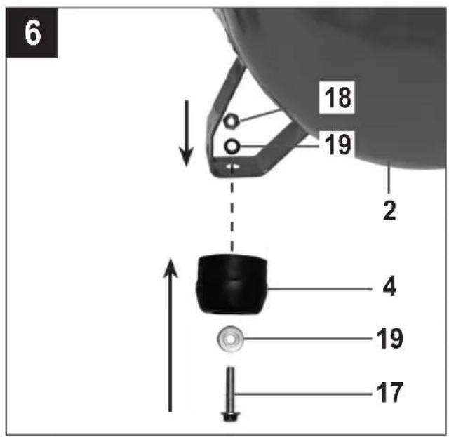
5.1.1 Fitting the supporting foot (only for B 255/10/50, B 350/10/50, B480/10/50)
Fit the supplied rubber stopper as shown in Fig. 6.
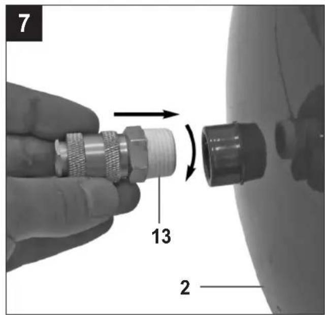
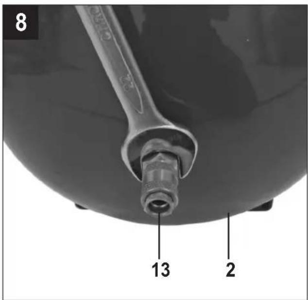
5.2 Fitting the quick-lock coupling for tank pressure (ref. 13)
Screw the quick-lock coupling for unregulated pressure (ref. 13) to the pressure vessel (shown in Figures 7 and 8.
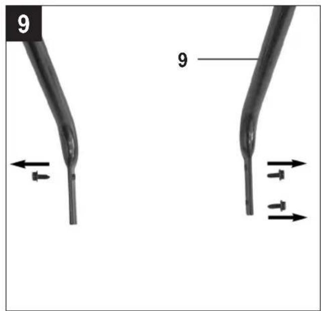
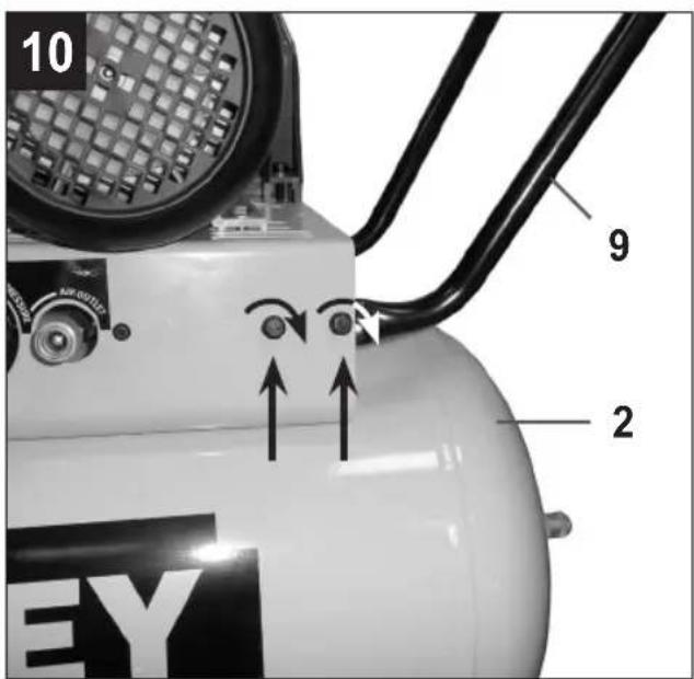
5.3 Fitting the transport handle (ref. 9)
Screw the transport handle (ref. 9) to the compressor as shown in Figures 9 and 10.
5.4 Voltage
5.4.1 Single-phase version 230 V / 50 Hz
The compressor is equipped with a mains cable with shock-proof plug. This can be connected to any 230V \~ 50Hz shock-proof socket which is protected by a 16 A fuse. Before you use the machine, make sure that the mains voltage complies with the specifications on the rating plate. Long supply cables, extensionable reels etc. cause a drop in voltage and can impede motor start-up. In the case of low temperatures below +5°C, motor start-up is jeopardized as a result of stiffness.
5.4.1.1 Connection of the mains plug (electrical information for the BS plug)

Important!
The wires in the mains lead fitted to this product are coloured in accordance with the code shown in fig. 25.
- This product is double insulated and does not require a connection to earth.
• The 3 pin plug must comply to BS1363/A.
• Fuse must comply to BS1362.
If for any reason the 13 amp plug fitted to this product requires replacement it must be wired in accordance with the following instruction:
Do not connect the brown (live) or blue (neutral) to the earth pin marked 'E' on the 3 pin plug.
Connect the Blue wire to the terminal marked Neutral (N). Connect the Brown wire to the terminal. marked
Live (L). Ensure that the outer insulation is to switch off the compressor, press the red knob (ref. by the cord grip and that the wires are not trapped 8) in again.
when replacing the plug cover. The mains lead on this product is fitted with a 13 amp (BS1363/A) plug. A 13 amp (BS1362) fuse must be fitted in the plug.
If in doubt consult a qualified electrician
There are no user serviceable parts inside this product except those referred to in the manual. Always re servicing to qualified service personnel. Never remove any part of the casing unless qualified to do so; this unit contains dangerous voltages.

Warnasg!
For your protection if this product is to be used outdoors it should not be exposed to rain or used in damp locations. Do not place the product on damp surfaces, use a workbench if available. For added protection use a suitable residual current device (R.C.D.) at the socket outlet.
Note: If the mains cable requires replacing it must be replaced with an identical one and fitted by a qualified person.
5.4.2 3-phase version 400 V / 50 Hz
- The compressor is equipped with a mains cans, with a 16A CEE plug. This plug has a phase converter. Before you put the equipment into operation, check whether the motor rotates in the correct direction (see the direction arrow on the V-belt cover) by switching on the compressor briefly. If the compressor motor rotates in the wrong direction, you must correct the rotating field by reversing the phase converter in the plug (use a screwdriver to depress the phase converter slightly and turn it through 180^ ).
- The motor is equipped with an overload switch the compressor overloads, the overload switch will switch off the equipment automatically to protect the compressor from overheating. If the overload switch triggers, wait for the compressor to cool down.
- Long supply cables, extensions, cable reels etc cause a drop in voltage and can impede motor start-up.
- In the case of low temperatures below +5°C, motor start-up is jeopardized as a result of stiffness.
5.5 On/Off switch (ref. 8)
5.5.1 Single-phase version (Fig. 2a)
To switch on the compressor, pull out the red knob (ref.
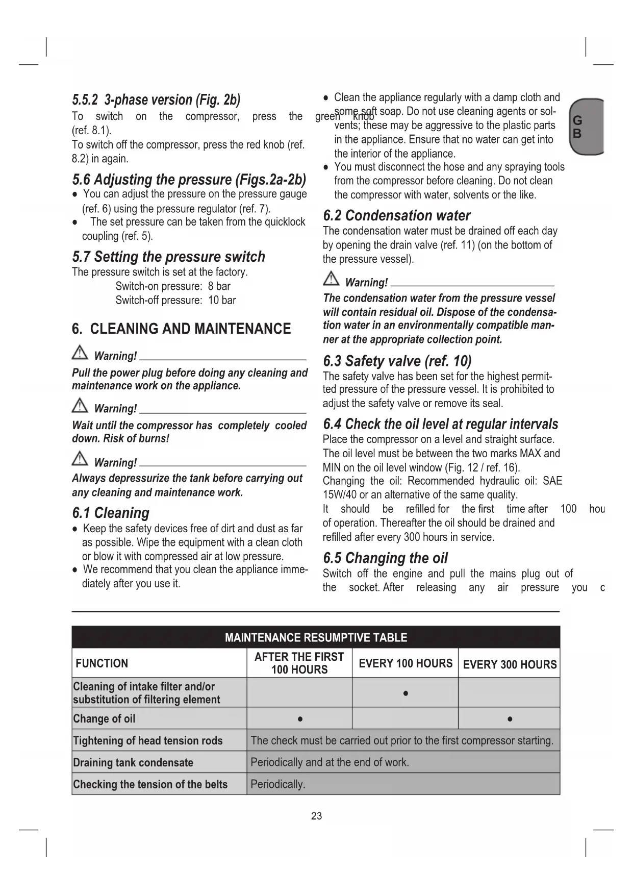
5.5.2 3-phase version (Fig. 2b)
To switch on the compressor, press the (ref. 8.1).
To switch off the compressor, press the red knob (ref. 8.2) in again.
5.6 Adjusting the pressure (Figs.2a-2b)
- You can adjust the pressure on the pressure gauge (ref. 6) using the pressure regulator (ref. 7).
- The set pressure can be taken from the quicklock coupling (ref. 5).
5.7 Setting the pressure switch
The pressure switch is set at the factory.
Switch-on pressure: 8 bar
Switch-off pressure: 10 bar
6. CLEANING AND MAINTENANCE

Warning!
Pull the power plug before doing any cleaning and maintenance work on the appliance.

Warning!
Wait until the compressor has completely cooled down. Risk of burns!

Warning!
Always depressurize the tank before carrying out any cleaning and maintenance work.
6.1 Cleaning
- Keep the safety devices free of dirt and dust as far as possible. Wipe the equipment with a clean cloth or blow it with compressed air at low pressure.
-
We recommend that you clean the appliance immediately after you use it.
-
Clean the appliance regularly with a damp cloth and some soft soap. Do not use cleaning agents or solvents; these may be aggressive to the plastic parts in the appliance. Ensure that no water can get into the interior of the appliance.
- You must disconnect the hose and any spraying tools from the compressor before cleaning. Do not clean the compressor with water, solvents or the like.
6.2 Condensation water
The condensation water must be drained off each day by opening the drain valve (ref. 11) (on the bottom of the pressure vessel).

Warning!
The condensation water from the pressure vessel will contain residual oil. Dispose of the condensation water in an environmentally compatible manner at the appropriate collection point.
6.3 Safety valve (ref. 10)
The safety valve has been set for the highest permitted pressure of the pressure vessel. It is prohibited to adjust the safety valve or remove its seal.
6.4 Check the oil level at regular intervals
Place the compressor on a level and straight surface. The oil level must be between the two marks MAX and MIN on the oil level window (Fig. 12 / ref. 16).
Changing the oil: Recommended hydraulic oil: SAE 15W/40 or an alternative of the same quality.
It should be refilled for the first time after 100 hours of operation. Thereafter the oil should be drained and refilled after every 300 hours in service.
6.5 Changing the oil
Switch off the engine and pull the mains plug out of the socket. After releasing any air pressure you c
| MAINTENANCE RESUMPTIVE TABLE | |||
| FUNCTION | AFTER THE FIRST 100 HOURS | EVERY 100 HOURS | EVERY 300 HOURS |
| Cleaning of intake filter and/or substitution of filtering element | ● | ||
| Change of oil | ● | ● | |
| Tightening of head tension rods | The check must be carried out prior to the first compressor starting. | ||
| Draining tank condensate | Periodically and at the end of work. | ||
| Checking the tension of the belts | Periodically. | ||
unscrew the oil drainage screw (ref. 15) from the compressor pump. To prevent the oil from running out in an uncontrolled manner, hold a small metal chute under the opening and collect the oil in a vess does not drain out completely, we recommend tilting the compressor slightly.
Dispose of the old oil at a drop-off point for old oil. When the oil has drained out, re-fit the screw (ref. 15). Fill new oil through the oil filler opening (ref. 14) until it comes up to the required level. Then replace the oil sealing plug (ref. 14).
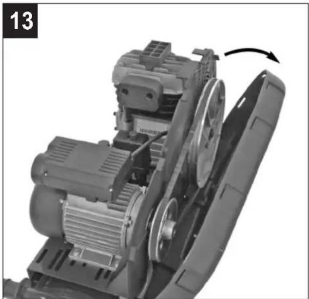
6.6 Retensioning the V-belt (Figs.13-15)
- Pull out the power plug and remove the safety guard for the V-belt.
- Slacken the four motor fixing screws (A).
- Shift the motor until the V-belt is to point where it can still be depressed by approx. 1-2 cm at the longest free position.
- Retighten the motor fixing screws (A) and refit safety guard for the V-belt.
6.7 Tightening of head tension rods
- Check that all screws (in particular those of the head of the unit) are tightly drawn up (fig. 24).
- The check must be carried out prior to the first compressor starting.
TIGHTENING OF HEAD TENSION RODS
| NmMin. torque | NmMax. torque | |
| Screw M6 9 11 | ||
| Screw M8 22 27 | ||
| Screw M10 45 55 | ||
| Screw M12 76 93 | ||
| Screw M14 121 148 |
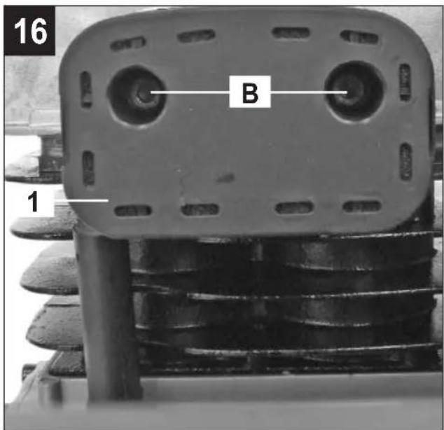
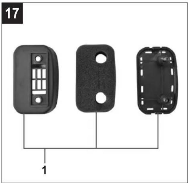
6.8 Cleaning the intake filter (ref. 1)
The intake filter prevents dust and dirt being drawn in. It is essential to clean this filter after at least every 100 hours in service. A clogged intake filter will decrease the compressor's performance dramatically. Undo the two Allen screws (B). You can then remove the filter from the two halves of the plastic housing, tap it to remove the dirt, blast it down with low-pressure compressed air (approx. 3 bar) and re-insert it (Figures 16-17-18).
6.9 Storage
Warning!
sPull the mains,ug out of the socket and ventilate the appliance and all connected pneumatic tools.
Switch off the compressor and make sure that it is secured in such a way that it cannot be started up again by any unauthorized person.
Warning!
Store the compressor only in a dry location which is not accessible to unauthorized persons. Always store upright, never tilted!
7. DISPOSAL AND RECYCLING
The unit and its accessories are made of various types of material, such as metal and plastic. Defective components must be disposed of as special your dealer or your local council.
8. POSSIBLE FAULTS AND RELATED PERMITTED REMEDIES
Request the assistance of a qualified electrician for operations on electric components (cables, motor, pressure switch, electric panel, etc).
| FAULT CAUSE REMEDY | ||
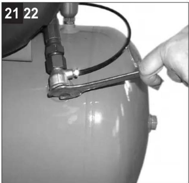
| Air leak from the valve of the pressure switch. | Check valve does not perform its function correctly due to wear or dirt on the seal. | Unscrew the hex-shaped head of the check valve, clean the housing and the special rubber disk (replace if worn). Re-assembler and tighten carefully (figures 21-22). |
| Condensate drainage cock open. | Close the condensate drainage cock. | |
| Rilsan hose not inserted correctly in pressure switch. | Insert the Rilsan hose correctly inside the pressure switch. | |
| Reduction of efficiency, frequent start-up. Low pressure values. | Excessively high consumption. | Decrease the demand of compressed air. |
| Leaks from joints and/or pipes. | Change gaskets. | |
| Clogging of the suction filter. | Clean/replace the suction filter (figures 16-17-18). | |
| Slipping of the belt. Check belt tension (fig. 15). | ||
| The motor and/or the compressor overheat irregularly. | Insufficient ventilation. Improve ambient conditions. | |
| Closing of air ducts. | Check and if necessary clean the air filter. | |
| Insufficient lubrication. Top up or change oil. | ||
| After an attempt to start the compressor, it stops due to tripping of the thermal cutout caused by forcing of the motor. | Start-up with head of the compressor charged. | Release the compressor head by using the pressure switch push button. |
| Low temperature. Improve ambient conditions. | ||
| Voltage too low. | Check that the mains voltage matches that of the dataplate. Eliminate any extensions. | |
| Incorrect or insufficient lubrication. | Check level, top up and if necessary change the oil. | |
| Inefficient electrovalve. Call the Service Center. | ||


| FAULT CAUSE REMEDY | ||
| During operation, the compressor stops for no apparent reason. | Tripping of the thermal cutout of the motor. | Check level oil. |
| Single-stage, mono-phase versions: operate on the button of the pressure switch returning this to the OFF position (par. 5.5.1). Reset the thermal cutout (fig. 19) and restart (par. 5.5.1). If the fault persists, call the Service Center. | ||
| Versions with delta-star starter: operate on the button of the thermal cutout located inside the box of the electric panel (fig. 20) and restart (fig. 2b). If the fault persists, call the Service Center. | ||
| Other versions: Operate on the button of the pressure switch returning this to the OFF position and then to ON again. If the fault persists, call the Service Center. | ||
| Electric fault. Call the Service Center. | ||
| When operating, the compressor vibrates and the motor emits an irregular buzzing sound. If it stops, it does not restart although the sound of the motor is present. | Single-phase motors: faulty capacitor. | Have the capacitor replaced. |
| 3-phase motors: One of the phases of the 3-phase power supply is missing due probably to blowing of a fuse. | Check the fuses inside the electric panel or the electric box and if necessary replace those that have been damaged (fig. 23). | |
| Irregular presence of oil in the network. | Too much oil inside the unit. Check oil level. | |
| Wear on segments. Call the Service Center. | ||
| Leaking of condensate from the vent cock. | Presence of dirt/grit inside the cock. | Clean the cock. |
Any other type of operation must be carried out by authorized Service Centers, requesting original parts. Tampering with the machine may impair its safety and in any case make the warranty null and void.
8. POSSIBLES ANOMALIES ET INTERVENTIONS ADMISES
5.5 Interruptor ON/OFF (8)
5.5.1 Versiones monofásicas (fig. 2a)
2. BESCHRIJVING VAN HET APPARAAT
5.5 AAN/UIT-schakelaar (ref. 8)
5.5.1 Monofase-versie (fig. 2a)
5.5 Av/På-bryter (ref. 8)
5.5.1 Enkeltfaseversjon (Fig. 2a)
6.3 Sikkerhetsventil (ref. 10)
⚠️ CE TREBUIE SĂ EVITAȚI
⚠️ NI U KOJEM SLUČAJU
4. ÜLESSEADMISJUHISED


- Preserve this handbook for future reference
- PRECAUTIONS
- ▲ THINGS TO DO
- ▲ THINGS NOT TO DO
- ▲ THINGS YOU SHOULD KNOW
- LAYOUT
- SCOPE OF USE
- POINTS TO NOTE WHEN SETTING UP THE COMPRESSOR
- ASSEMBLY AND STARTING
- Warning!
- Fitting the wheels (Figs. 4-5)
- Fitting the supporting foot (only for B 255/10/50, B 350/10/50, B480/10/50)
- Fitting the quick-lock coupling for tank pressure (ref. 13)
- Fitting the transport handle (ref. 9)
- Voltage
- Single-phase version 230 V / 50 Hz
- Connection of the mains plug (electrical information for the BS plug)
- Important!
- Do not connect the brown (live) or blue (neutral) to the earth pin marked 'E' on the 3 pin plug.
- If in doubt consult a qualified electrician
- Warnasg!
- 3-phase version 400 V / 50 Hz
- On/Off switch (ref. 8)
- Single-phase version (Fig. 2a)
- 3-phase version (Fig. 2b)
- Adjusting the pressure (Figs.2a-2b)
- Setting the pressure switch
- CLEANING AND MAINTENANCE
- Cleaning
- Condensation water
- Safety valve (ref. 10)
- Check the oil level at regular intervals
- Changing the oil
- Retensioning the V-belt (Figs.13-15)
- Tightening of head tension rods
- Cleaning the intake filter (ref. 1)
- Storage
- DISPOSAL AND RECYCLING
- POSSIBLE FAULTS AND RELATED PERMITTED REMEDIES
- POSSIBLES ANOMALIES ET INTERVENTIONS ADMISES
- Interruptor ON/OFF (8)
- Versiones monofásicas (fig. 2a)
- BESCHRIJVING VAN HET APPARAAT
- AAN/UIT-schakelaar (ref. 8)
- Monofase-versie (fig. 2a)
- Av/På-bryter (ref. 8)
- Enkeltfaseversjon (Fig. 2a)
- Sikkerhetsventil (ref. 10)
- ⚠️ CE TREBUIE SĂ EVITAȚI
- ⚠️ NI U KOJEM SLUČAJU
- ÜLESSEADMISJUHISED
Brand : STANLEY
Model : B 40010200 T
Category : Compressor