Ellisse Canalizzabile - Pan Cola - Free user manual and instructions
Find the device manual for free Ellisse Canalizzabile Cola in PDF.
| Product Type | Ductable wood pellet stove |
| Brand | Cola |
| Model | Ellisse Canalizzabile |
| Dimensions (H x W x D) | 1082 x 831 x 565 mm |
| Weight | 168 kg |
| Useful thermal power | Nominal: 12.83 kW / Reduced: 3.66 kW |
| Thermal efficiency | 89.25% to 95.00% |
| Hourly pellet consumption | Nominal: 3.04 kg/h / Reduced: 0.81 kg/h |
| Pellet hopper capacity | 21 kg |
| Fuel | Wood pellets conforming to UNI EN14961-2 class A1 (diameter 6 mm, length 6-30 mm, ash content max 1.5%) |
| Power supply | 230 V - 50 Hz - 6 A |
| Power consumption | Ignition: 420 W / Nominal operation: 140 W |
| Flue outlet diameter | 80 mm |
| Required draft | 10 to 14 Pa (0.10 to 0.14 mbar) |
| Flue gas temperature | Nominal: 202.5 °C / Reduced: 86.7 °C |
| CO emissions at 13% O2 | Nominal: 0.01% (164.8 mg/m³) / Reduced: 0.01% (79.6 mg/m³) |
| Safety distances (rear / sides / floor) | 200 mm / 300 mm / 0 mm |
| Main functions | Automatic ignition and shutdown, weekly programming, remote control, power regulation (1 to 5), room thermostat, standby mode, ductable (2 hot air outlets) |
| Safety | Safety thermostat (hopper), vacuum switch, flow meter, overvoltage protection (2A fuse), shutdown in case of power failure with automatic restart, anti-explosion flaps |
| Maintenance and cleaning | Daily cleaning of the brazier, every 2-3 days of the ash pan, weekly cleaning of the glass, annual maintenance by a professional, maintenance reminder after 1800 hours |
| Supplied accessories | Power cable, user manual, door opening key, remote control |
| Reference standards | EN 14785:2006, CEI EN 60335-1, CEI EN 55014-1, CEI EN 61000-3-2 |
| Warranty | According to general terms - warranty is void in case of non-compliance with the instructions in the manual |
Frequently Asked Questions - Ellisse Canalizzabile Cola
User questions about Ellisse Canalizzabile Cola
0 question about this device. Answer the ones you know or ask your own.
Ask a new question about this device
Download the instructions for your Pan in PDF format for free! Find your manual Ellisse Canalizzabile - Cola and take your electronic device back in hand. On this page are published all the documents necessary for the use of your device. Ellisse Canalizzabile by Cola.
USER MANUAL Ellisse Canalizzabile Cola
natural_image
Exterior view of a modern cylindrical industrial machine with white and black casing, yellow vent, and control panel (no visible text or symbols)484210470-M5_07/13 Hardware - M
Read the instructions carefully before installation, use and maintenance. The manual is an integral part of the unit.
COLA guarantees its products, except for parts subject to normal wear, in accordance with the current regulations. For the warranty terms, please contact the importer or the authorised agent who can integrate the compulsory warranty period with an additional period under his sole and exclusive responsibility.
The product warranty is invalidated for any trouble, breakage or accident due to failure to comply with or apply the instructions provided in this manual.
FR 70-102
natural_image
3D rendering of a cylindrical industrial device with internal compartments and ventilation grilles (no visible text or symbols)natural_image
Diagram of a mechanical device with an arrow indicating motion or force direction (no text or symbols)natural_image
Technical line drawing of a cylindrical mechanical or architectural component with internal structural details and arrows indicating features (no text or symbols present)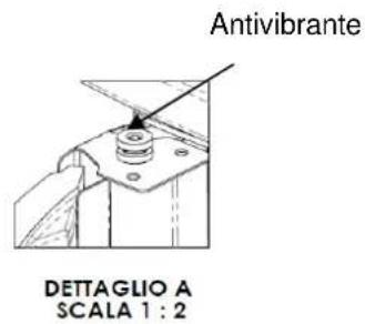
text_image
Antivibrante DETTAGLIO A SCALA 1 : 2Y
natural_image
Technical line drawing of a cylindrical industrial or server unit with internal compartments and ventilation grilles (no text or symbols)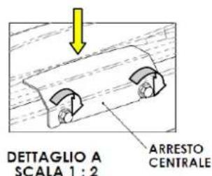
text_image
DET TAGLIO A SCALA 1 : 2 ARRESTO CENTRALE2.3 Presa d'aria
natural_image
3D architectural diagram showing a room with labeled components A, B, C and directional arrows indicating flow or movement (no text or symbols beyond labels)natural_image
Close-up of a computer control panel with buttons and dials (no visible text or symbols)text_image
Diagram of a remote control device with labeled buttons and indicator lightsnatural_image
Line drawing of a mobile phone case with four buttons and a battery (no text or symbols)natural_image
Simple line drawing of a rectangular container with a horizontal arrow pointing to the bottom (no text or symbols)text_image
Vertical toolbar with icons representing various mechanical or electrical components, including clock, gear, and directional indicators.natural_image
Close-up of a circular container filled with dark granular substance, no visible text or symbolsBraciere sporco
natural_image
Close-up of a perforated metal pipe or drain component (no text or symbols visible)Braciere pulito
natural_image
Close-up of a cylindrical mechanical component with a central square opening, mounted on a metal base (no visible text or symbols)text_image
Technical diagram of an internal combustion engine assembly with numbered components and directional arrows indicating flow or movement.Legenda :
text_image
Exploded view diagram of a mechanical assembly with numbered parts and directional arrow indicating motion
text_image
1 2 3 4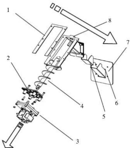
text_image
Technical diagram of a mechanical assembly with numbered components and directional arrows indicating motion or assembly.Legenda :
text_image
Technical diagram of a device with numbered components and an inset view of the control panel labeled 12.Legenda:
CE MARKING INFORMATION
COLA
CE _13
1.1. Introduction
1.2. Using the manual
1.3. Safety rules
1.4. Technical description
1.5. Permissible use and fuel
1.6. Accessories supplied
1.7. Reference standards
1.8. Dataplate
1.9. Stove decommissioning
1.10. Instructions for requesting assistance and replacement parts
2. TRANSPORT AND INSTALLATION
2.1. Packing, handling, shipment and transport
2.2. Place of installation, positioning and fire-prevention safety
2.3. Air inlet
2.4. Fume exhaust
2.4.1. Types of installation
2.5. Brazier and baffle position check
2.6. Hot air conduct
2.7. Electrical connection
2.8. Wiring diagram
2.9. Emergency
3. STOVE SAFETY
3.1. Safety distance from flammable materials
3.2. Fume exhaust safety
3.3. Combustion chamber overpressure safety
3.4. Overheating - pellet hopper temperature safety thermostat
3.5. Safety against flare-back in the pellet chute
3.6. Overcurrent electrical protection device
3.7. Power failure safety
3.8. Fume fan failure
4. STOVE USE
4.1. Introduction
4.2. Description of control panel
4.3. Lighting
4.3.1. Check before lighting
4.3.2. Startup stage
4.4. Work stage
4.5. Shutting down the stove
4.6. Menu
4.6.1 menu 01 – adjust fans
4.6.2 menu 02 - set clock
4.6.3 menu 03 – enable chrono
4.6.4 menu 04 – select language
4.6.5 menu 05 – standby mode
4.6.6 menu 06 - buzzer
4.6.7 menu 07 – initial loading
4.6.8 menu 08 – stove status
4.6.9 menu 09 – settings by technician
4.7 Remote control
4.7.1 replacing the battery
4.8 Thermostat – external chronothermostat
4.9 Hot air fans
4.9.1 Hot air flow setting
4.10 Idle period (end of season)
5 STOVE CLEANING
5.1 Cleaning the brazier
5.1 Cleaning the ash container
5.2 Cleaning the glass and air slots
5.3 Cleaning the fume extractor and combustion chamber
5.4 Cleaning the air flow meter
5.5 Cleaning the ceramic surfaces (ceramic models)
5.6 Cleaning the flue - flue connection
6 MAINTENANCE
6.1 Introduction
6.2 Removing the cladding
6.3 Stove internal parts
6.4 Electrical components
7 TROUBLESHOOTING
7.1 Alarm management
8 ENCLOSURES
8.1 CE marking information
1 GENERAL INFORMATION
1.1 Introduction
Dear Customer,
First of all we wish to thank you for the trust placed in us by purchasing one of our products. Please read and carefully follow the advice given in this installation, use and maintenance manual in order make best use of the product.
All the documents regarding the unit's certifications or declarations, in particular the Declaration of Conformity and Declaration of Performance, can be found through the website of the relevant trademark.
1.2 Using the manual
The Manufacturer reserves the right to make technical or aesthetic changes to the products at any time without notice.
Stove installation, use and maintenance operations must comply with the requirements given in this manual as well as the European, National, Regional, Provincial and Municipal regulations.
The drawings, measurements, diagrams and any other configurations are given only by way of example.
This manual is an integral part of the product; make sure it always stays with the stove, even if sold, transferred to another owner or installed in another place, so that it can be consulted at any time.
If lost or damaged, ask the Authorised Service Centre for a copy so that the stove always has its own manual.
| This symbol indicates the presence of an important message; failure to pay attention to it can result in serious damage to the stove and even injury | |
| Pay special attention to “words in bold face” |
1.3 Safety rules.
- Read the use and maintenance manual before installing, lighting and servicing the stove.
- Installation, the electrical connection, testing and maintenance must be carried out by a qualified and/or authorised technician.
- Connect the stove to an approved flue by means of an inspectionable terminal; several units can be connected only if allowed by the local regulations and by the flue inspection Body.
- Connect the stove to the suction system by means of a pipe or air inlet from outside.
- Connect the stove to an approved 230 V-50 Hz electrical socket.
- Make sure the electrical system and the sockets are suitable for the maximum absorption of the unit, specified on the label and in this manual.
- The stove must be unplugged and cold before carrying out any maintenance.
- Do not use flammable liquids or substances to light the stove or rekindle the flame: when the stove is lit, pellet ignition is automatic.
- The pellet stove must only be fed with wood pellets having the characteristics described in this manual.
- The stove must not be used as an incinerator.
- Never block the combustion air inlet and fume outlet openings.
- Do not handle easily flammable or explosive substances near the stove while it is operating.
- Do not remove or modify the pellet hopper protection grille or the safety devices.
- Do not operate the stove with the fire door open and/or the glass damaged or broken.
- During operation the intense heat generated by combustion of the pellets makes the external surfaces of the stove very hot, and in particular the fire door, handle and flue pipe. Therefore avoid contact with these parts without suitable protection.
- Keep objects that are flammable and/or not heat resistant at a suitably safe distance.
- Clean the brazier regularly every time the stove is lit or whenever reloading pellets.
- Have the duct and smoke baffles inside the combustion chamber cleaned regularly by qualified personnel.
- Avoid the creation of smoke and unburnt products during lighting and/or normal operation; an excessive accumulation of unburnt pellets in the brazier must be eliminated manually before carrying out relighting.
- Warn children and guests about the hazards described above.
- In case of operating problems, the stove can be relit only after eliminating the cause of the problem.
- Any tampering and/or unauthorised replacements with non-original parts of the stove can create a risk for the user's safety and relieves the manufacturer of any civil or penal liability.
- Only use original replacement parts recommended by the manufacturer.

The manufacturer declines any liability for problems, damage or accidents caused by failure to follow or apply the instructions contained in this manual.
1.4 Technical description
The stove works exclusively on pellets, providing healthy and safe heat in the room. The stove's automatic control systems guarantee optimum heat output and complete combustion; there are also safety systems to guarantee safe operation for the stove parts and for the user.
When correctly installed, the unit works in any outside climatic conditions, and in any case in critical conditions (strong wind, frost, etc.) the safety systems can cut in, shutting down the stove.
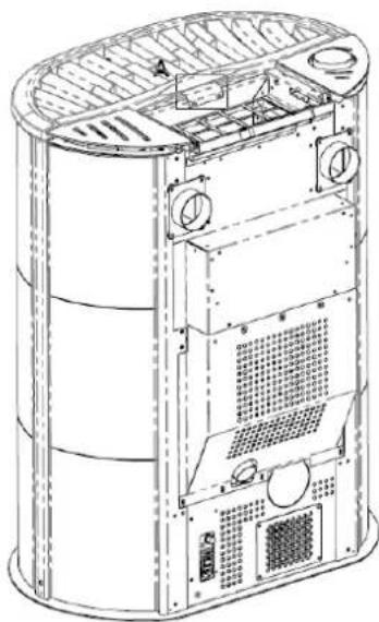
The stove model ELLISSE CAN with nominal power of 12,83 kW ensures a maximum heatable volume of 293 m3, considering the coefficient of a building's energy requirements equal to 35W/m3, and may vary depending on the insulation, type and climatic zone which are important variables for the correct choice of unit.
D - Flue pipe connection diam. 80 mm
F - Control panel model F047
G - Ducted air outlet connections duct A -duct C diam. 80 mm
H - Fume exhaust pipe rear connection diam. 80 mm (OPTIONAL)
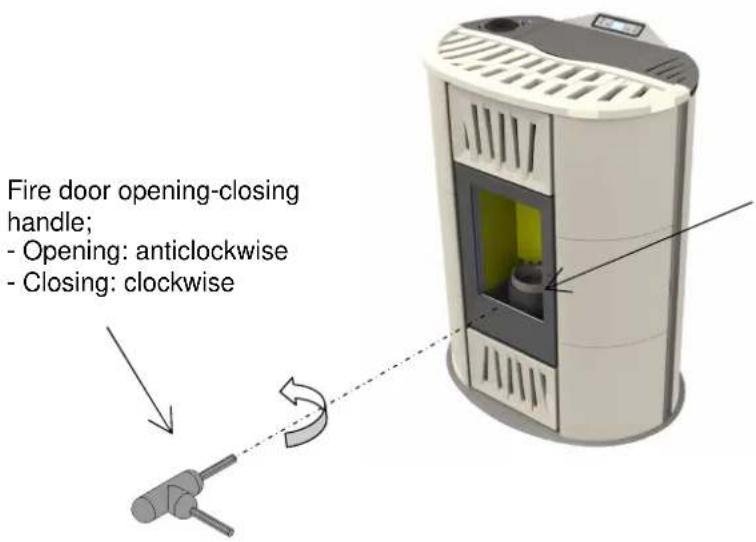
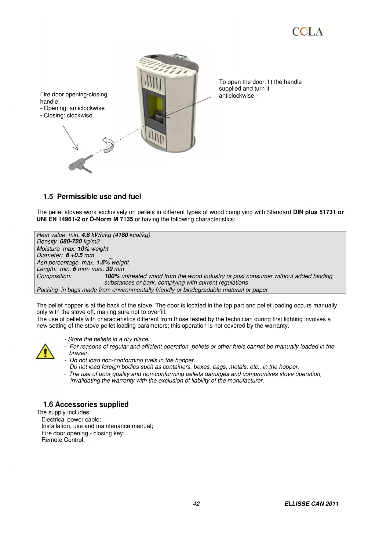
text_image
Fire door opening-closing handle; - Opening: anticlockwise - Closing: clockwiseTo open the door, fit the handle supplied and turn it anticlockwise
1.5 Permissible use and fuel
The pellet stoves work exclusively on pellets in different types of wood complying with Standard DIN plus 51731 or UNI EN 14961-2 or Ö-Norm M 7135 or having the following characteristics:
| Heat value min. 4.8 kWh/kg (4180 kcal/kg) | |
| Density 680-720 kg/m3 | |
| Moisture max. 10% weight | |
| Diameter: 6 +0.5 mm | |
| Ash percentage max. 1.5% weight | |
| Length: min. 6 mm- max. 30 mm | |
| Composition: | 100% untreated wood from the wood industry or post consumer without added binding substances or bark, complying with current regulations |
| Packing in bags made from environmentally friendly or biodegradable material or paper | |
The pellet hopper is at the back of the stove. The door is located in the top part and pellet loading occurs manually only with the stove off, making sure not to overfill.
The use of pellets with characteristics different from those tested by the technician during first lighting involves a new setting of the stove pellet loading parameters; this operation is not covered by the warranty.

- Store the pellets in a dry place.
- For reasons of regular and efficient operation, pellets or other fuels cannot be manually loaded in the brazier.
- Do not load non-conforming fuels in the hopper.
- Do not load foreign bodies such as containers, boxes, bags, metals, etc., in the hopper.
- The use of poor quality and non-conforming pellets damages and compromises stove operation, invalidating the warranty with the exclusion of liability of the manufacturer.
1.6 Accessories supplied
The supply includes:
Electrical power cable;
Installation, use and maintenance manual;
Fire door opening - closing key;
Remote Control.
1.7 Reference standards
| Standard UNI 10683:2012 : | Installation requirements for heat generators burning wood or other solid biofuels; |
| Standard UNI EN14785:2006 : | Requirements for design, manufacture, construction, safety and performance, instructions and marking, together with the relevant test methods for approval of units burning pellets; |
| Standard CEI EN 60335-1 : | Safety of electrical appliances for domestic and similar use - part 1; |
| Standard CEI EN 60335-2-102 : | Safety of electrical appliances for domestic and similar use - part 2; |
| Standard CEI EN 55014-1: | Electromagnetic resistance - Requirements for electrical appliances, electric tools and similar electric equipment - Part 1: Emission of interference; |
| Standard CEI EN 55014-2 : | Electromagnetic resistance - Requirements for electrical appliances, electric tools and similar electric equipment - Part 2: Immunity; Product family standard; |
| Standard CEI EN 61000-3-2 : | Limits for harmonic current emissions (Input current ≤ 16 A per phase); |
| Standard CEI EN 61000-3-3 : | Limitation of voltage fluctuations and flicker in low voltage supply systems for equipment with nominal current ≤ 16 A; |
| Standard CEI EN 62233 : | Measuring methods for electromagnetic fields of electrical household appliances and similar with reference to human exposure. |
| Standards DIN plus 51731 – UNI EN 14961-2 - Ö-Norm M 7135 : | Standards regarding the specifications and classification of pellets. |
1.8 Dataplate
The data plate is located on the inside of the pellet hopper door or on the back of the stove. It gives all the stove's characteristic data, including the manufacturer's details, serial number, CE marking, test laboratory and the Declaration of Performance reference number.
1.9 Stove decommissioning
When definitively deciding to not to use the stove any more, we recommend to disconnect the power supply and to empty the pallet tank completely. In order to eliminate the stove, it is necessary to packaged it with a strong packaging and then take contact with local organisation which follows the selling off operations respecting the local rules. Otherwise we recommend to back the stove directly to the distributor when buying a similar new one.
1.10 Instructions for requesting assistance and replacement parts
To request any assistance and/or replacement parts contact your dealer, area importer or the nearest authorised service centre, clearly specifying the following: stove model, serial number, date of purchase, list of replacement parts, details of faults or malfunctioning.

- All operations on components must be carried out by authorised and/or qualified personnel.
- Make sure all electrical connections are disconnected and that the stove is cold before any work on it.
- Only use original replacement parts.
2 TRANSPORT AND INSTALLATION
2.1 Packing, handling, shipment and transport
The stove complete with packing can be lifted using a lift truck, inserting the forks (of suitable length) in the special spaces in the wooden pallet. Make sure the equipment used for lifting and transport can take the weight of the stove, specified on the dataplate and in this manual.
Avoid taking the load in areas where it could be a danger if dropped.
Open the packing, remove the stove from the pallet and position it in the required place, making sure it complies with that provided for.
Set the stove down on the floor carefully without bumping and position it in the required place. Make sure the floor can take the weight of the stove, otherwise consult a specialised technician.
Disposal or recycling of the packing must be carried out by the end-user in compliance with the current local regulations.
2.2 Place of installation, positioning and fire-prevention safety
The place of installation must be sufficiently ventilated to allow the removal of any combustion smoke leaks.
The unit is suitable for operation in domestic environments with min. temperature not below 0°C.
To prevent the risk of fire, the structures surrounding the stove must be protected from the heat.
Floors in wood or in any flammable material must be suitably protected at the base with steel or toughened glass panels; the protection must cover the base and also a certain area in front of the stove.
Any wooden boards or beams above or crossed by the flue must be suitably protected in conformity with the requirements of the specific current installation standards.
The minimum front distance for the protection of flammable objects is 1.5 m. The minimum safety distances from flammable materials must comply with the following table:
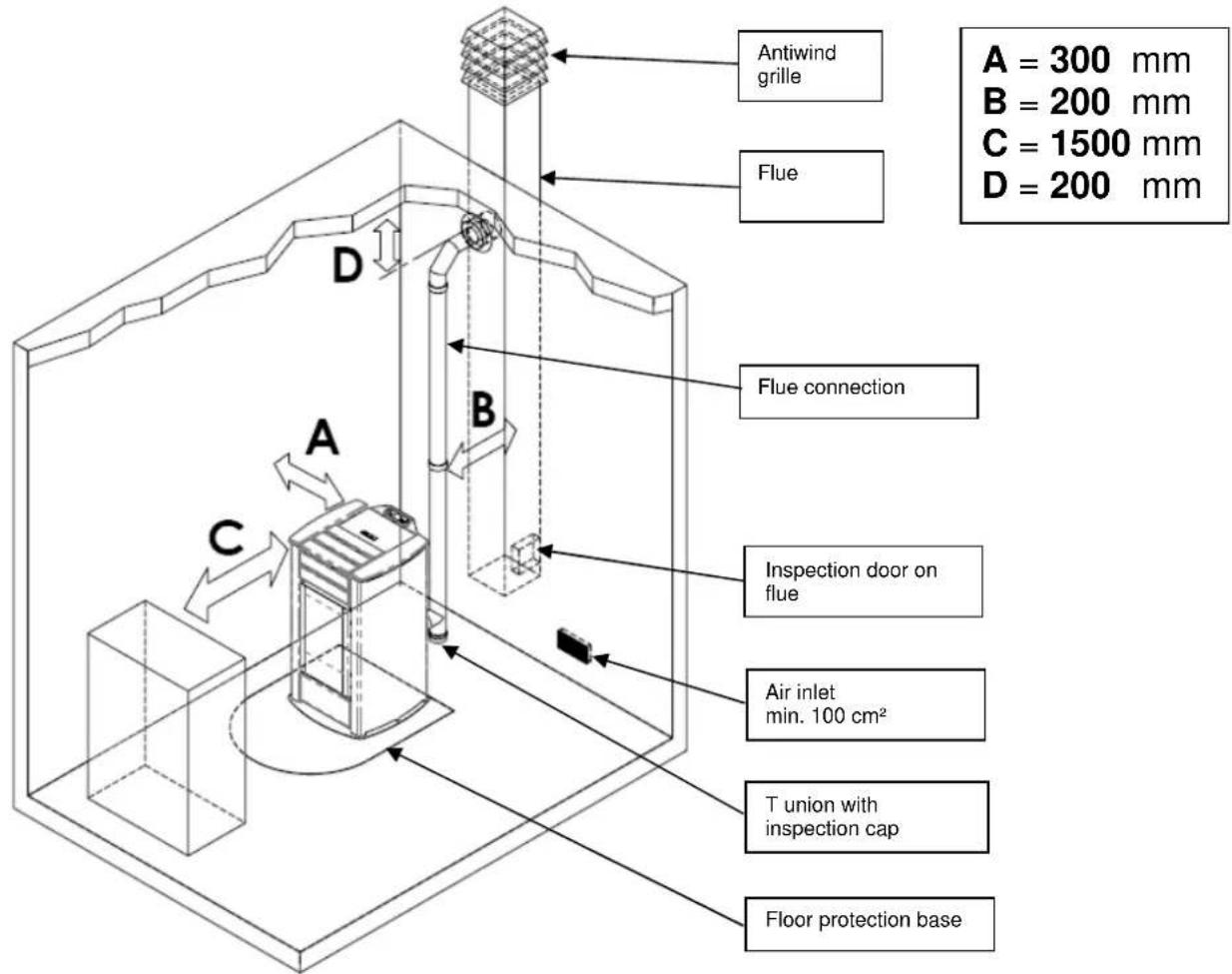
text_image
Antiwind grille Flue A = 300 mm B = 200 mm C = 1500 mm D = 200 mm Flue connection A B C Inspection door on flue Air inlet min. 100 cm² T union with inspection cap Floor protection baseEvery installation must provide for an easily accessible technical space for periodical maintenance.
The stove is provided with 4 adjustable feet to facilitate positioning on not perfectly flat floors. To adjust the height, tilt the stove slightly and turn the feet as required.
The stove is supplied with the ambient sensor fixed through a wrapper on the back of the stove; we recommend to remove the wrapper and to locate the sensor in the best position possible as to improve the temperature registration in accordance with the ambient context and the length of the cable.
As for temperature registration done at a certain distance we recommend to install the ambient thermostat/ambient programming clock-thermostat – see. par.4.8.

- The stove cannot be installed in bedrooms, bathrooms and in general in rooms where another heating unit is already installed without an independent air inflow.
- With wooden floors, install a floor protection base in conformity with the current regulations.
- Suitable fire-prevention devices should be arranged for any eventuality.
- Do not install the stove in places with an explosive atmosphere.
COLA
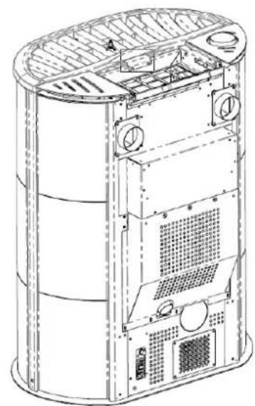
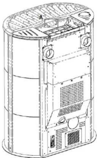
The appropriately wrapped and protected cover is inside the packing:
- unpack it carefully, check the integrity of the part and install it after placement of the stove, as follows:
X - position the cover, respecting the position of the 4 vibration dampers (detail A) on the stove which allow its centring.
Y - secure the cover in place, fixing the middle stop without forcing, as shown in the figure.
X

natural_image
Technical line drawing of a cylindrical mechanical or architectural component with internal structural details and mounting points (no text or symbols)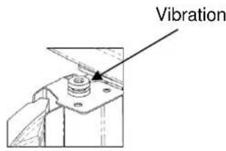
text_image
VibrationDETAIL A SCALE 1:2
Y
natural_image
Technical line drawing of a cylindrical industrial device with internal components and ventilation ducts (no text or symbols)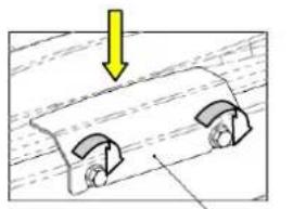
natural_image
Diagram showing a mechanical component with two curved parts and a yellow arrow indicating downward motion (no text or symbols)DETAIL A SCALE 1:2
2.3 Air inlet
The stove air inlet pipe or intake is located at the back and is round and 50 mm in diameter.
A quantity of air at least equal to that necessary for combustion must flow in the room where the stove is installed; therefore the combustion air necessary to ensure correct operation of the stove must be drawn:
from the room, provided there is a wall air inlet near the stove, communicating with the outside and of minimum area 100 cm ^2 suitably protected externally by a grille;
or with direct connection to the outside with an appropriate pipe having a minimum internal diameter of 50 mm and maximum length of 1.5 m, provided with antiwind protection at the end (down bend).
The air inflow can also be obtained from a room adjoining that of installation, provided the flow can occur freely through permanent openings to the outside; the room must not be used as a garage, for storing combustible materials or for activities with fire risk.
2.4 Fume exhaust
The fumes can be exhausted through a connection to a conventional flue or an external duct with double wall or insulated pipe.
The fume exhaust connections must guarantee a minimum draught of 10 Pa so that the evacuation of fumes is assured in case of a temporary power failure.

- The installer must check the efficiency and state of the flue and its conformity with the local, national and European regulations.
- Certified pipes and connections with adequate seals guaranteeing their tightness must be used.
- In case of fire, shut down the stove, promptly call the fire department, and avoid continual attempts to extinguish it.
- Clean the flue and respective connection at least once a year.
2.4.12.4.1 Types of installation
Listed below are definitions and requirements for correct installation of an exhaust flue in accordance with Italian Standard UNI10683:
FLUE : a vertical duct for collecting and expelling, at an appropriate height from ground, the fumes coming from a single unit and, where permitted, more than one.
FLUE technical requirements: it must be fumetight, isolated and insulated depending on its use;
- it must have a mainly vertical path with axis deviation < 45°;
- it must be at a suitable distance from flammable materials with insulation or air gap;
- it must preferably have a constant, free and independent round internal section;
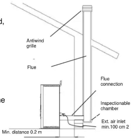
- it is advisable for the flue to have an inspectionable chamber for the collection of solid materials
- and any condensate, placed under the beginning of the fume duct.
text_image
Antiwind grille Flue Flue connection Inspectionable chamber Ext. air inlet min.100 cm 2 Min. distance 0.2 mFLUE CONNECTION or DUCT: duct or connection element between the unit and flue for evacuation of fumes.
DUCT technical requirements: - it must not cross rooms in which the installation of combustion units is not allowed;
- flexible metal tubes or fibre cement pipes are prohibited;
- the use of counter-sloping elements is prohibited;
- horizontal sections must have an upward slope of at least 3°;
- the length of the horizontal section must be minimal and not more than 3 m;
- there must not be more than 3 changes of direction, without the T union;
- the fume duct must have a constant section and allow the recovery of soot.
- with change of direction > 90° a max. of 2 bends can be used with length in horizontal projection not exceeding 2 m.
CHIMNEY CAP : a device placed on the top of the flue to facilitate the dispersion of fumes into the atmosphere. CHIMNEY CAP technical requirements : it must have a section equivalent to that of the flue;
- it must have a useful section not less than double the internal section of the flue;
- it must prevent the entry of rain and foreign bodies and ensure the discharge of fumes in any atmospheric condition;
- it must ensure an adequate dilution of fumes and be positioned outside the backflow area;
- it must be without mechanical means of suction.

The direct discharge of fumes must take place on the roof and not towards closed spaces (even open air).
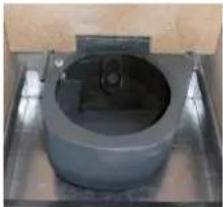
2.5 Brazier and baffle position check
Before lighting the stove make sure the brazier is in the correct position, i.e. fitted in the special slots. Also make sure the top smoke baffle is properly fitted. A wrongly positioned baffle can result in malfunctioning and excessive blackening of the glass.

At every stove lighting, check the correct position of the brazier on the brazier holder.
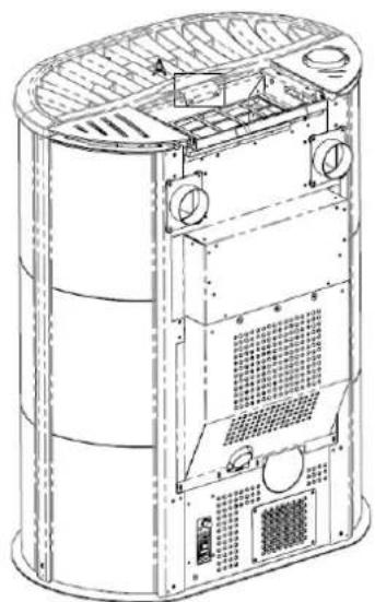
2.6 Hot air ducting
The ELLISSE ductable model has two rear connections of 80 mm external diam. for ducting the hot air flows generated by two centrifugal fans inside the stove in heat exchange with the side walls of the combustion chamber. To create the ducting system:
- use pipes with internal diam. of 80 mm able to resist temperatures of at least 150°C;
- use pipes that are smooth inside, insulated or isolated;
- reduce, as far as possible, the ducting path and the single pipe section must not be longer than 10 m;
- avoid constrictions or section reductions, tight bends and downsloping sections.
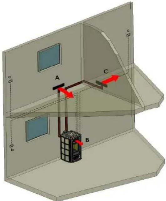
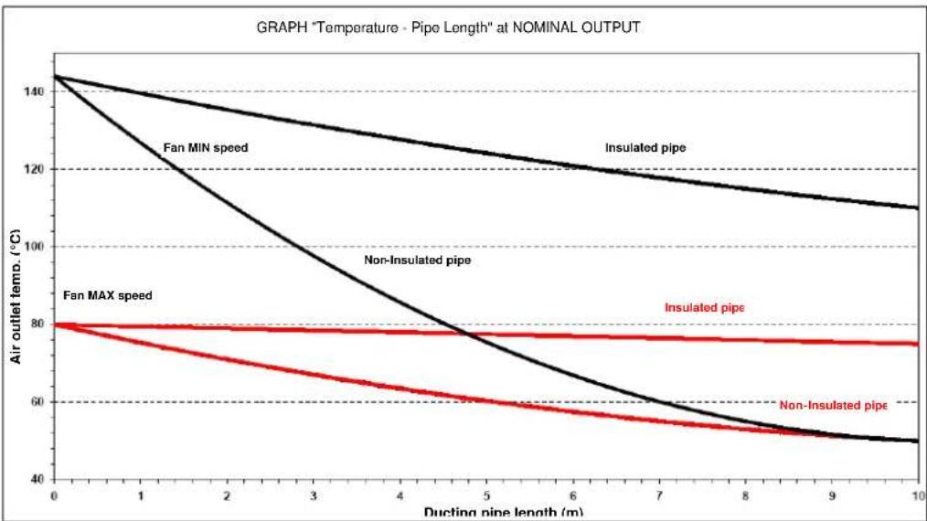
Given below is an example of a ducting system in a residential building and graph of the temperature curve depending on the length of the ducting pipe outside the stove, insulated and non-insulated in the condition of hot air maximum and minimum hot air flow rate/speed DUCT A and C.
text_image
A B C D e dA – left ducting rear hot air flow;
B – room middle hot air flow from middle fan;
C - right ducting rear hot air flow;
a – ducting A local external thermostat;
b – stove room B external probe;
c - ducting C local external thermostat;
line
| Ducting pipe length (m) | Fan MIN speed | Insulated pipe | Non-Insulated pipe | Fan MAX speed | Insulated pipe | | ----------------------- | ------------- | -------------- | ------------------ | ------------- | -------------- | | 0 | 140 | 140 | 140 | 80 | 80 | | 1 | 130 | 135 | 125 | 80 | 80 | | 2 | 120 | 130 | 110 | 80 | 80 | | 3 | 110 | 125 | 95 | 80 | 80 | | 4 | 100 | 120 | 80 | 80 | 80 | | 5 | 90 | 115 | 65 | 80 | 80 | | 6 | 80 | 110 | 55 | 80 | 80 | | 7 | 70 | 105 | 50 | 80 | 80 | | 8 | 60 | 100 | 45 | 80 | 80 | | 9 | 50 | 95 | 40 | 80 | 80 | | 10 | 45 | 90 | 35 | 80 | 80 |2.7 Electrical connection
Connect one end of the power cable to the rear socket of the stove, and the other to the wall socket.
The voltage supplied by the system must match that specified on the stove dataplate and in the technical data section of this manual.
During stove idle periods it is advisable to remove the power cable.

- Make sure the electrical system is equipped with an earth and differential switch in accordance with the current Regulations.
- The power cable must never touch the stove exhaust pipe.
2.8 Wiring diagram
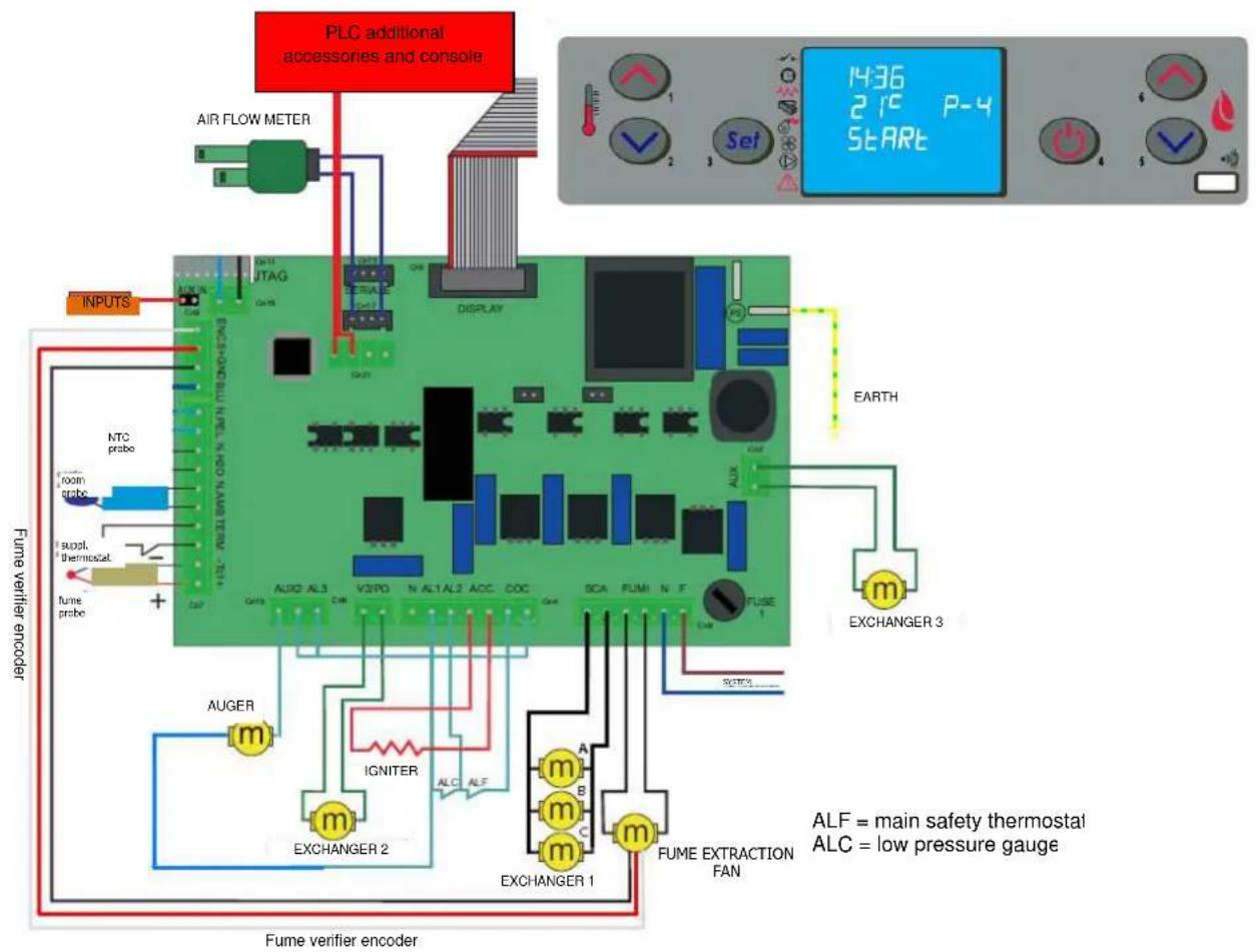
text_image
PLC additional accessories and console AIR FLOW METER NPUTS NTC probe toon probe supl. thermostat fume probe + Fume verifier encoder AUGER m IGNITER EXCHANGER 2 ALC ALF EXCHANGER 1 m m m m FUME EXTRACTION FAN EARTH 1436 21°C P-4 START EXCHANGER 3 ALF = main safety thermostat ALC = low pressure gauge2.9 Emergency
Suitable fire-prevention devices should be arranged for any eventuality. In case of a fire, proceed as follows:

- Immediately disconnect the plug.
- Extinguish the fire using suitable fire-extinguishers.
- Call the fire department immediately.
- Do not use jets of waters to extinguish the fire.
3 STOVE SAFETY
3.1 Safety distance from flammable materials
To prevent the risk of fire, stove positioning must respect a minimum distance from flammable materials, according to that given in the technical table of the manual and on the dataplate.
Pay attention to the type of floor: for delicate and flammable materials it is advisable to use plates in steel or toughened glass as a support base (see section 2 - Transport and Installation). In case of particularly fragile objects such as furniture, curtains or sofas, increase the stove distance considerably.
3.2 Fume exhaust safety
In normal operation the combustion chamber is in a negative pressure, guaranteeing seal against possible smoke leaks in the room. If a certain vacuum level is not reached or the fume exhaust outlet is blocked, the vacuum switch detects the lack of a negative pressure inside the combustion chamber or the air flow meter detects a lack of air flow and, through the electronic controller, switches off the auger rotation motor, signalling the anomaly with a message on the control panel 'AL 8 NO NEG PRESS' or 'AL 9 INSUF DRAUGHT'.
3.3 Combustion chamber overpressure safety
Any and/or sudden overpressures in the combustion fumes inside the chamber and fume exhaust ducts are discharged by opening of the safety valves located on the heat exchanger. During normal operation these valves are kept closed by their weight and the negative pressure in the combustion chamber, guaranteeing a seal against any smoke escaping.

Periodically check closing, the integrity of the device and its operation.
3.4 Overheating - pellet hopper temperature safety thermostat
natural_image
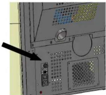
Close-up of a control panel with buttons and dials, no visible text or symbolsA temperature probe is connected to a safety thermostat above the pellet chute which automatically interrupts the pellet supply in case of excessive heating > 85°C. In this case the extractor and/or fans continue working, allowing the stove to cool down rapidly. The fault is displayed on the control panel with a message 'AL 7 THERMAL SAF'. In case of activation, proceed as follows:
Allow the stove to cool down for at least 45 minutes.
Reset the thermostat by pressing the button near the switch on the back of the stove, after unscrewing the protection cap (figure opposite).
Restart the stove normally.
3.5 Safety against flare-back in the pellet chute
The solutions preventing flare-back are:
▶ negative pressure in the combustion chamber see par. 3.2.
the siphon shape of the pellet chute.
the hopper temperature safety see par. 3.4.
3.6 Overcurrent protection device
The unit is protected against overcurrent by 2A fuses on the power supply of the main stove switch located at the back.
3.7 Power failure safety
In case of brief power failures, the stove relights automatically.
A temporary power failure does not limit stove safety and the hopper temperature does not reach high values (< 85°C), given the small quantity of pellets burning in the brazier.
This anomaly can result in some smoke briefly escaping into the room, which does not involve any risk.

Do not tamper with the safety devices.
3.8 Fume extractor fan failure
If the fume extractor fan stops for any reason, the electronic controller instantly stops the pellet feed, displaying the message 'AL 4 FAN FAIL'.
4 STOVE USE
4.1 Introduction
The pellet stove has the advantage of combining heat from a wood flame with the convenience of automatic management of temperature and the possibility of weekly programming of lighting and shutdown.
Connection to an external thermostat and/or chronothermostat is possible for detecting the temperature in a different place from where the stove is installed.
For safe and reliable use:
- when lighting and using the stove the first time, unpleasant odours may be created, therefore air the room thoroughly;
- the hopper must only be filled with pellets; make sure the bag does not come into contact with the hot surfaces of the stove:
- do not put any fuel other than the prescribed pellets in the hopper;
- the stove must not be used as a waste incinerator;
- the stove must only operate with the fire door always closed.
- the fire door seals must be checked periodically to prevent air from entering;
- to guarantee efficient performance and correct operation it is necessary to carry out periodical cleaning of the brazier every time pellets are loaded;
- when lighting the stove for the first time, allow it to heat up gradually by setting low operating temperatures (see section on temperature setting);
- during lighting, operation and shutdown, the stove may creak a little due to the heat expansion.
4.2 Description of control panel
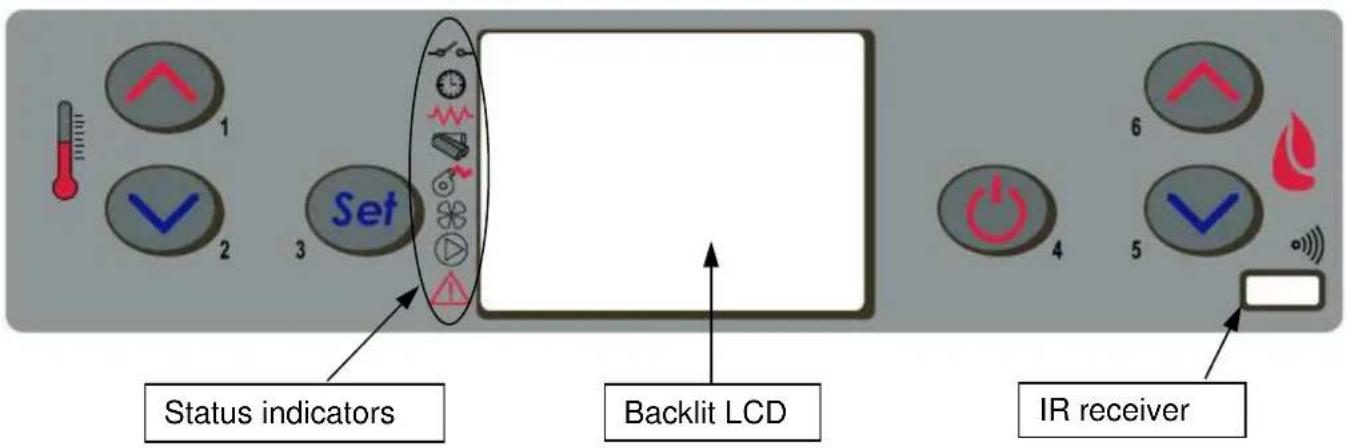
The control panel comprises a backlit LCD, on/off button 'P4', SET/MENU button 'P3', four menu buttons 'P1', 'P2', 'P5', 'P6', and six stove operation status LEDs.
text_image
1 2 Set 3 Status indicators Backlit LCD 4 5 6 IR receiverThe panel enables stove lighting and shutdown, adjustment during operation and the setting of management and maintenance programmes.
The display shows all the information on stove operation status.
To access the menus, proceed as follows:
- press the SET button 'P3';
- press the buttons 'P5', 'P6' to scroll the various menus;
- press one of the increase/decrease buttons 'P1', 'P2', to set the required parameter;
- press the SET button 'P3' to confirm the parameter value.
On accessing the menu it is possible to obtain the various types of displays and carry out the available settings depending on the access level.
Given below is the table of controls and respective messages displayed during programming or setting operation parameters:
| Button | Description | Mode | Action |
| 1 | Increase temperature | PROGRAMMING | Modify/increase selected menu value |
| WORK/OFF | Increase room thermostat temperature value | ||
| 2 | Decrease temperature | PROGRAMMING | Modify/decrease selected menu value |
| WORK/OFF | Decrease room thermostat temperature value | ||
| 3 | Setting/menu | Access MENU | |
| MENU | Access next submenu level | ||
| PROGRAMMING | Set value and go to next menu item | ||
| 4 | ON/OFF reset | WORK | Press for 2 seconds to switch the stove on or off (if off or on) |
| BLOCK | Resets the stove and returns it to off status | ||
| MENU/PROGRAMMING | Goes to higher menu level. The modifications made are memorised | ||
| 5 | Decrease power | WORK/OFF | Modifies stove heat output |
| MENU | Go to next menu item | ||
| PROGRAMMING | Return to next submenu item. The modifications made are memorised | ||
| 6 | Increase power | WORK/OFF | Modifies exchanger speed |
| MENU | Go to previous menu item | ||
| PROGRAMMING | Go to previous submenu item. The modifications made are memorised |
The Figure opposite describes the meaning of the status indicators in the left part of the display.
Activation of one of the segments on the display signals activation of the corresponding device according to the list opposite.
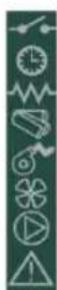
external contact
chrono
igniter
auger
fume extractor
exchanger
not used
alarm
4.3 Lighting
4.3.14.3.1 Check before lighting
Before lighting the stove:
- make sure you have read and understood that given in the manual;
- the hopper must be filled with pellets;
- the combustion chamber must be clean;
- the brazier must be completely free, cleaned of any combustion residuals and correctly fitted in the brazier holder;
- check hermetic closing of the fire door and ash pan;
- check the connection of the power cable and switching to ON/1 of the switch located on the back of the stove.
COLA

- At first startup, remove all the components (instructions/label) that could burn from the stove firebox and glass.
- Any lightings done after long stove idle periods require the renewal of any pellets that have been inside the hopper for a long time, in being a damp fuel no longer suitable for combustion, and complete cleaning of the combustion chamber.
4.3.2 Startup stage
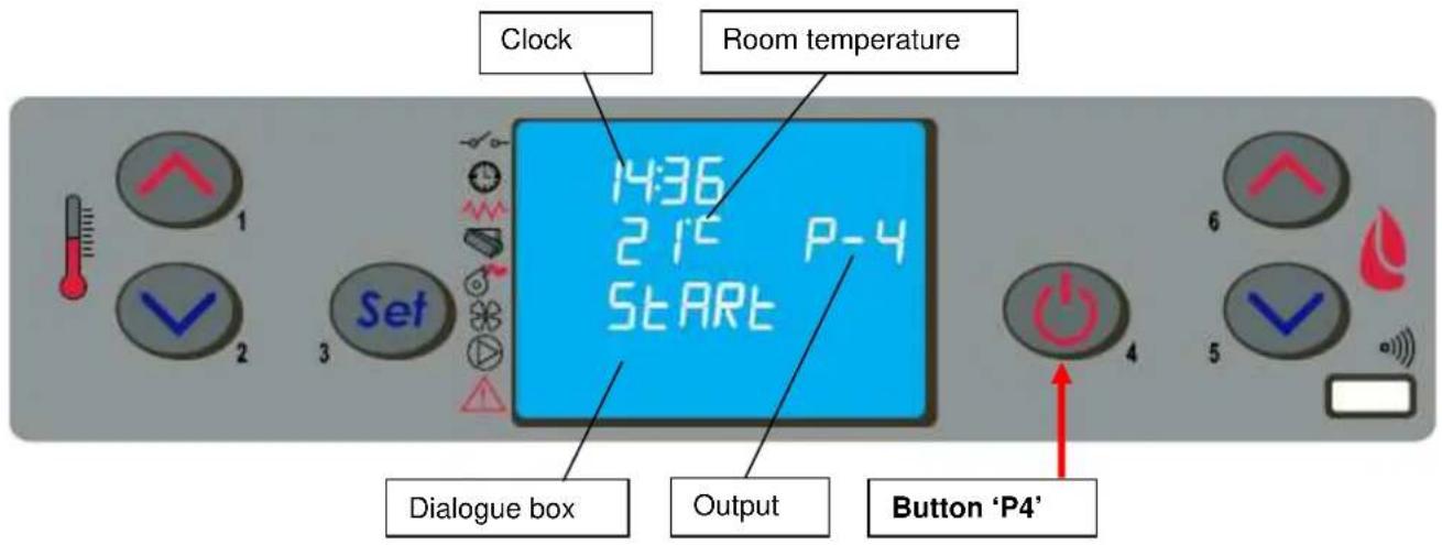
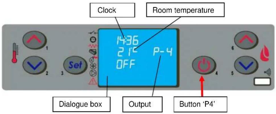
To light the stove, press the button 'P4' for 3 seconds: the message 'START' will appear on the display. The stage is automatic and managed entirely by the electronic controller without the possibility of changing the parameters.
text_image
Clock Room temperature 14:36 21° P-4 START Dialogue box Output Button 'P4'The stove carries out the startup stages in sequence according to the procedures defined by the parameters that manage levels and times, reaching the work condition unless anomalies or alarms occur, according to the following table:
| Status | Duration | Devices | Conditions for going to next status | |||
| Igniter | Fume exhaust | Auger | Exch. | |||
| OFF | - | OFF | OFF | OFF | OFF | ON/OFF |
| START - CLEANING | Pr33 | OFF | ON | OFF | OFF | After time Pr33 |
| PREHEAT | Pr34 | ON | ON | OFF | OFF | After timePr34 |
| PELLET PREFILL | Pr40 | ON | ON | ON | OFF | After time Pr40 |
| WAITING FLAME | Pr41 | ON | ON | OFF | OFF | After timePr41 |
| PELLET LOAD | - | ON | ON | ON | OFF | Fume temperature > Pr13 |
| FIRE PRESENT | Pr02 | OFF | ON | ON | ON | After time Pr02 |
| WORK | - | OFF | ON | ON | ON | Room temperature < SET temperatureFume temperature < Pr14 |
| MODULATES WORK | - | OFF | ON | ON | ON | Room temperature < SET temperatureFume temperature < Pr14 |
| BRAZIER CLEANING | Pr12 | OFF | ON | ON | ON | Every Pr03 |
| WORK | - | OFF | ON | ON | ON | ON/OFF to switch off |
| FINAL CLEANING | Pr39 (*) | OFF | ON | OFF | - | (*) Pr39 starts from when fume T.< Pr13 |
After a certain time has elapsed, if the fume temperature has not reached the minimum permissible value the stove goes in alarm status.

- Do not use flammable liquids to light the stove.
- In case of persistent failed lighting, contact the Service Centre.
4.4 Work stage
After the 'STARTUP' stage, the stove goes to the 'WORK' mode which represents the normal operation mode. The user can adjust the heat output from the max. value of 5 to a min. of 1 with the buttons 'P5' and 'P6'.
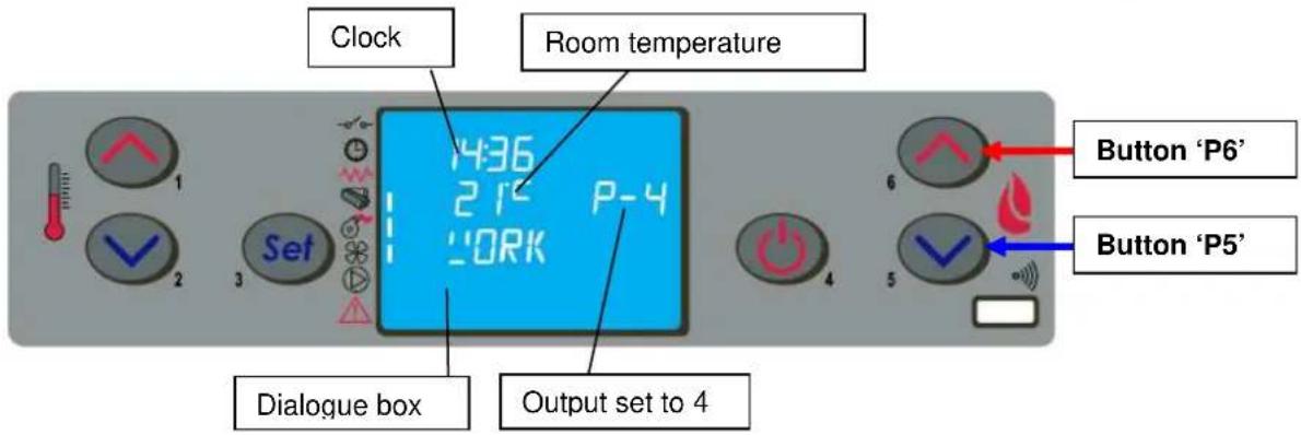
text_image
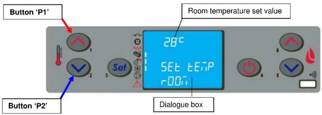
Clock Room temperature 436 21° P-4 WORK Set Dialogue box Output set to 4 Button 'P6' Button 'P5'As well as adjusting the heat output, it is also possible to adjust the room temperature directly on the control panel with the buttons 'P1' and 'P2': the display shows the current SET temperature status.
For the ventilation of hot air, the stove automatically regulates the speed according to the set heat output.
text_image
Button 'P1' Room temperature set value 28°C SET temperature r001 Dialogue box Button 'P2'
- Make sure to check the pellet level in the hopper so that the flame does not go out due to lack of pellets.
- Make sure the stove is off when loading pellets.
- The pellet hopper lid must always remain closed; it must only be opened when loading fuel.
- The bags of pellets must be kept at least 1.5 m from the stove.
When the fume temperature rises the maximum value set, the display will show the message 'MODULA F' and the stove starts the modulation of the flame aithomatically. On the contrary when the temperature goes over 280°C the display will show the alarm 'ALARM HOT FUMI' and the stove will start the switch-off procedure.
If the STANDBY mode is activated, the stove is shut down with a delay time after reaching the SET temperature. Restart occurs when the room temperature is lower than a certain fixed value with respect to the room temperature.
During normal operation in work mode, the 'CLEANING FIRE POT' mode is activated at fixed intervals for a set duration.
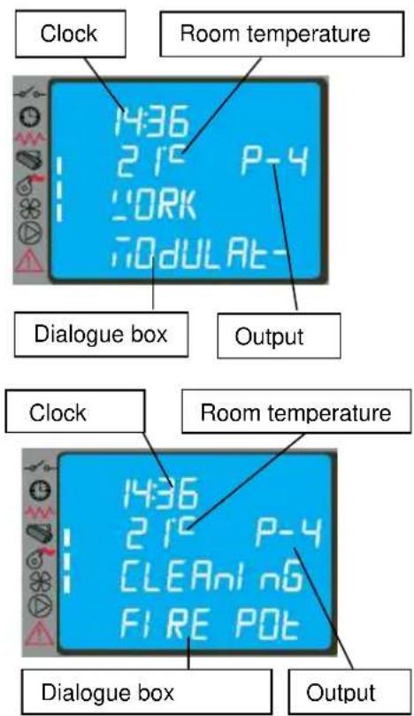
text_image
Clock Room temperature 1436 215 P-4 WORK 70dULAt- Dialogue box Output Clock Room temperature 1436 215 P-4 CLEANl n6 FIRE POT Dialogue box Output4.5 Shutting down
To shut down the stove, just press the button 'P4' for about 2 seconds.
The auger is stopped immediately and the fume extractor is brought to high speed, with the message 'CLEANING FIRE POT' displayed; both fume extraction and air ventilation motors remain on until the stove temperature has lowered sufficiently.
text_image
Clock Room temperature 1436 215 P-4 OFF Dialogue box Output Button 'P4'At the end of the operation the message 'OFF' appears in the dialogue box.
During the shutdown stage the stove cannot be restarted until the fume temperature has fallen below a set value for a fixed time, with the message 'WAITING COOL' appearing in the dialogue box.
4.6 Menu
Press the button 'P3' (SET) to access the menu; this is divided into various items and levels for accessing the settings of the electronic controller.
The following table summarises the menu structure with the selections available to the user.
| Level 1 Level 2 | Level 3 | Level 4 | Value | |
| 01 – Adjust fans | Select value | |||
| 02 – Set clock | 01 - day Day | |||
| 02 - hours Hours | ||||
| 03 - minutes Minutes | ||||
| 04 - day Day | ||||
| 05 - month Month | ||||
| 06 - year Year | ||||
| Level 1 Level 2 | Level 3 | Level 4 | Value | |
| 03 – Set chrono | ||||
| 01 – enable chrono | ||||
| 01 – enable chrono | on / off | |||
| 02 – day program | ||||
| 01 – day chrono | on / off | |||
| 02 – start 1 day | time | |||
| 03 – stop 1 day | time | |||
| 04 – start 2 day | time | |||
| 05 – stop 2 day | time | |||
| 03 – week program | ||||
| 01 – week chrono | on / off | |||
| 02 – start 1 day | time | |||
| 03 – stop 1 day time | ||||
| 04 – Monday prog 1 | on / off | |||
| 05 – Tuesday prog 1 | on / off | |||
| 06 – Wednesday prog 1 | on / off | |||
| 07 – Thursday prog 1 | on / off | |||
| 08 – Friday prog 1 | on / off | |||
| 09 – Saturday prog 1 | on / off | |||
| 10 – Sunday prog 1 | on / off | |||
| 11 – start prog 2 time | ||||
| 12 – stop prog 2 time | ||||
| 13 – Monday prog 2 | on / off | |||
| 14 – Tuesday prog 2 | on / off | |||
| 15 – Wednesday prog 2 | on / off | |||
| 16 – Thursday prog 2 | on / off | |||
| 17 – Friday prog 2 | on / off | |||
| 18 – Saturday prog 2 | on / off | |||
| 19 – Sunday prog 2 | on / off | |||
| 20 – start prog 3 time | ||||
| 21 – stop prog 3 time | ||||
| 22 – Monday prog 3 | on / off | |||
| 23 – Tuesday prog 3 | on / off | |||
| 24 – Wednesday prog 3 | on / off | |||
| 25 – Thursday prog 3 | on / off | |||
| 26 – Friday prog 3 | on / off | |||
| 27 – Saturday prog 3 | on / off | |||
| 28 – Sunday prog 3 | on / off | |||
| 29 – start prog 4 time | ||||
| 30 – stop prog 4 time | ||||
| 31 – Monday prog 4 | on / off | |||
| 32 – Tuesday prog 4 | on / off | |||
| 33 – Wednesday prog 4 | on / off | |||
| 34 – Thursday prog 4 | on / off | |||
| 35 – Friday prog 4 | on / off | |||
| 36 – Saturday prog 4 | on / off | |||
| 37 – Sunday prog 4 | on / off | |||
| 04 – week-end program | ||||
| 01 – week-end chron | on / off | |||
| 02 – start 1 | ||||
| 03 – stop 1 | ||||
| 04 – start 2 | ||||
| 05 – stop 2 | ||||
| Level 1 | Level 2 | Level 3 | Level 4 | Value |
| 04 – Select language | ||||
| 01 - Italian | set | |||
| 02 - French | set | |||
| 03 - English | set | |||
| 04 - German | set | |||
| 05 – Standby mode | on / off | |||
| 06 – Buzzer | on / off | |||
| 07 – Initial loading | set | |||
| 08 – Stove status | - |
4.6.1 Menu 01 – adjust fans
Before adjusting the speed of the fans it is advisable to adjust the hot air flows according to that given in par. 4.9. If enabled, the item of menu 01 adjusts fan speed in the DUCTED versions; in the ELLISSE DUCTABLE version there are 3 heat exchange air fans:
A – left ducting hot air FAN;
B – middle room hot air FAN;
C - right ducting hot air FAN;
The speed of middle fan B is only automatic and fixed according to the selected output, whereas the speeds of fans A and C are settable by the customer according to the following table:
| Setting Fan A | Fan C | |
| A (automatic) | Corresponding to the selected output Corresponding to the selected output | |
| 0 | Fan deactivated Fan deactivated | |
| 1 | Speed fixed by technical parameters Speed fixed by technical parameters | |
| 2 | Speed fixed by technical parameters | Speed fixed by technical parameters |
| 3 | Speed fixed by technical parameters | Speed fixed by technical parameters |
| 4 | Speed fixed by technical parameters | Speed fixed by technical parameters |
| 5 | Speed fixed by technical parameters | Speed fixed by technical parameters |
To select the speeds, use the buttons P1 (fan A) and P2 (fan C).
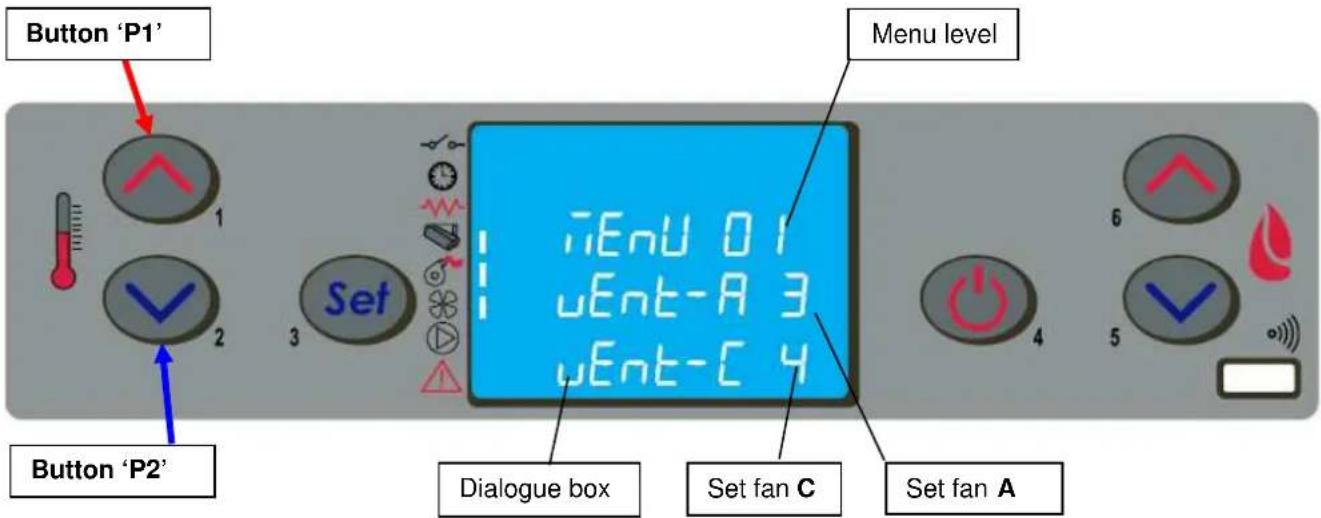
text_image
Button 'P1' Button 'P2' Set Menu level iEnu 01 uEnt-A 3 uEnt-C 4 Dialogue box Set fan C Set fan A4.6.2 Menu 02 - set clock
The electronic control device has a lithium battery mod. CR2032 of 3 Volt inside. It allows the internal clock with own autonomy; if the clock signal does not appear when the stove is off or when switching the stove again a series of "0000" appears, it means it has to be substituted and you need to call one of our service point authorised for its substitution.
4.6.3 Menu 03 – enable chrono
It allows to enable and disable all the thermostat functions programmed; with the set ON you activate this function and it appears the led [D] related to it. When the daily, weekly, or week-end program is set you can see on the upper right side of the display it appears the led [C].
By accessing the submenu: DAY PROGRAM, the daily chronothermostat functions can be enabled/disabled and set.
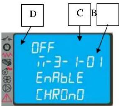
text_image
D C B OFF i-3-1-01 Enable CHRONOIt is possible to set two operation phases delimited by the times set according to the following table where the OFF setting tells the clock to ignore the command.
| Selection | Meaning | Possible values |
| START 1 | Activation time | ora - OFF |
| STOP 1 | Deactivation time | ora - OFF |
| START 2 | Activation time | ora - OFF |
| STOP 2 | Deactivation time | ora - OFF |
COLA
text_image
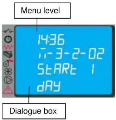
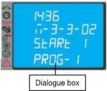
Menu level 14:36 7-3-2-02 START 1 DAY Dialogue boxBy accessing the submenu: WEEK PROGRAM it is possible to enable/disable and set the weekly chronothermostat functions. The weekly programmer has 4 independent programmes whose final effect consists of a combination of the 4 programmings. The weekly programmer can be activated/deactivated; also, by setting OFF in the times field, the clock ignores the corresponding command.

Carry out programming making sure not to overlap the hours of activation and/or deactivation on the same day in different programmes.
text_image
14:36 --3-3-02 START 1 PROG-1 Dialogue box| PROGRAMME 1 | |||
| Menu level | Selection | Meaning | Possible values |
| 03-03-02 | START PROG 1 | Activation time | ora - OFF |
| 03-03-03 | STOP PROG 1 | Deactivation time | ora - OFF |
| 03-03-04 | LUNEDI PROG 1 | Reference day | on/off |
| 03-03-05 | MARTEDI PROG 1 | on/off | |
| 03-03-06 | MERCOLEDI PROG 1 | on/off | |
| 03-03-07 | GIOVEDI PROG 1 | on/off | |
| 03-03-08 | VENERDI PROG 1 | on/off | |
| 03-03-09 | SABATO PROG 1 | on/off | |
| 03-03-10 | DOMENICA PROG 1 | on/off | |
| PROGRAMME 2 | |||
| Menu level | Selection | Meaning | Possible values |
| 03-03-11 | START PROG 2 | Activation time | ora - OFF |
| 03-03-12 | STOP PROG 2 | Deactivation time | ora - OFF |
| 03-03-13 | LUNEDI PROG 2 | Reference day | on/off |
| 03-03-14 | MARTEDI PROG 2 | on/off | |
| 03-03-15 | MERCOLEDI PROG 2 | on/off | |
| 03-03-16 | GIOVEDI PROG 2 | on/off | |
| 03-03-17 | VENERDI PROG 2 | on/off | |
| 03-03-18 | SABATO PROG 2 | on/off | |
| 03-03-19 | DOMENICA PROG 2 | on/off | |
| PROGRAMME 3 | |||
| Menu level | Selection | Meaning | Possible values |
| 03-03-20 | START PROG 3 | Activation time | cra - OFF |
| 03-03-21 | STOP PROG 3 | Deactivation time | cra - OFF |
| 03-03-22 | LUNEDI PROG 3 | Reference day | on/off |
| 03-03-23 | MARTEDI PROG 3 | on/off | |
| 03-03-24 | MERCOLEDI PROG 3 | on/off | |
| 03-03-25 | GIOVEDI PROG 3 | on/off | |
| 03-03-26 | VENERDI PROG 3 | on/off | |
| 03-03-27 | SABATO PROG 3 | on/off | |
| 03-03-28 | DOMENICA PROG 3 | on/off | |
| PROGRAMME 4 | |||
| Menu level | Selection | Meaning | Possible values |
| 03-03-29 | START PROG 4 | Activation time | ora - OFF |
| 03-03-30 | STOP PROG 4 | Deactivation time | ora - OFF |
| 03-03-31 | LUNEDI PROG 4 | Reference day | on/off |
| 03-03-32 | MARTEDI PROG 4 | on/off | |
| 03-03-33 | MERCOLEDI PROG 4 | on/off | |
| 03-03-34 | GIOVEDI PROG 4 | on/off | |
| 03-03-35 | VENERDI PROG 4 | on/off | |
| 03-03-36 | SABATO PROG 4 | on/off | |
| 03-03-37 | DOMENICA PROG 4 | on/off | |
By accessing the submenu: WEEK-END PROGRAM it is possible to enable/disable and set the week-end (Saturday - Sunday) chronothermostat functions.

Activate WEEK-END programming only after deactivating the weekly programming.
In order to avoid unwanted start and shutdown operations, activate only one programme at a time.
Deactivate the daily programme if the weekly programme is required; with this setting it is advisable to deactivate the week-end programme.
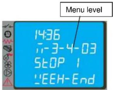
text_image
14:36 7-3-4-03 STOP 1 "EEH-End4.6.4 Menu 04 – select language
With this selection it is possible to select the dialogue language from those available entered in the menu, and namely:
- ITALIAN
- FRENCH
- ENGLISH
- GERMAN
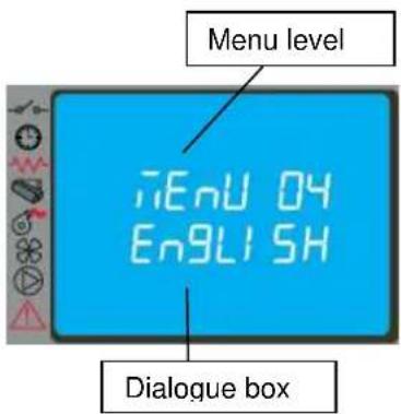
text_image
Menu level iEnU 04 ENGLISH Dialogue box4.6.5 Menu 05 – standby mode
With the selection of STANDBY mode (ON selection) the stove shuts down automatically after the room temperature has remained above the SET value for a fixed time.
The next automatic relighting will be possible only when the room temperature falls below the set value entered in the parameters table (default 2°C).
The manual commands from the control panel or remote control have priority over programming.
4.6.6 Menu 06 – buzzer
With this selection it is possible to activate/deactivate stove acoustic signalling.
4.6.7 Menu 07 – initial loading
The setting of INITIAL LOADING allows pellet preloading for a time equal to 90 sec. with the stove off or cold. It is started with the button P1 and stopped with the button P4.
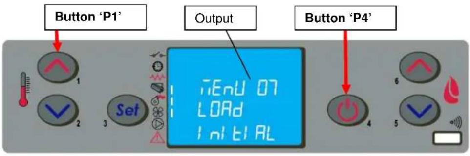
text_image
Button 'P1' Output Button 'P4'4.6.8 Menu 08 – stove status
With this selection it is possible to display the instantaneous stove status giving the operating status of the various devices connected to it; various pages placed in succession are available for monitoring.
4.6.9 Menu 09 – settings by technician
This selection is reserved for the authorised technician of the COLA service centre.

Modification of the technical parameters of menu 09 must be done by authorised and competent personnel; any changes made at random can cause serious damage for which COLA declines any liability.
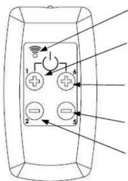
4.7 Remote control
The remote control works with the settings made in the control panel and allows stove lighting-shutdown, and adjustment of the required output and temperature. Since this device transmits through an infrared diode, it must be pointed at the receiver unit in the control panel.
The remote control allows the following operations:
text_image
Diagram of a remote control panel with labeled buttons and indicator lightsL : LED lit up by pressing any button
Button P1+P6 : Stove lighting-shutdown
Button P1: Increase room temperature
Button P6: Increase output level
Button P5: Decrease output level
Button P2: Decrease room temperature
natural_image
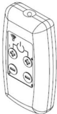
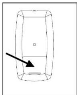
Line drawing of a handheld electronic device with four buttons and a display screen (no text or symbols)4.7.1 4.7.1 Replacing the battery
The remote control comes without the battery; it works with a battery placed in the lower part of the device.
To fit or replace the battery, proceed as follows:
- Open the cover on the back of the remote control;
- Replace the 12V battery model p23ga, respecting the polarity;
- Close the remote control;
- Check that it works properly;
natural_image
Simple line drawing of a rectangular container with an arrow pointing to its side (no text or symbols)
- Keep the remote control away from heat sources and water.
- The battery of the remote control must be replaced and disposed of in a safe way, respecting the local regulations.
4.8 Thermostat - external chronothermostat
The unit controls the room temperature by means of its own digital thermostat whose function is to detect the temperature through a probe and lower the heat output when the set temperature is reached.
To use an external thermostat, contact an authorised technician and proceed as follows:
- turn off the power by means of the main switch on the back and detach the power cable;
- remove the side panel to access the electronic controller;
- referring to the wiring diagram, connect the two wires of thermostat to the respective board TERM terminals;
- refit everything and check correct operation.
The setting procedure is as follows:
- external thermostat: SET the temperature to 7°C;
- external chronothermostat: SET the temperature to 7°C and disable the chrono functions from the menu 03-01.
All the menu functions do not change for each of the settings and signalling of the connection occurs with lighting up of the segment LED on the status bar of the display.
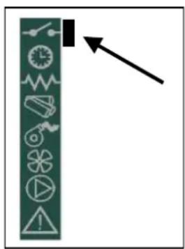
text_image
Vertical toolbar with icons and an arrow pointing to a black square, likely indicating navigation or function4.9 Hot air fans
The ELLISSE DUCTABLE stove has three fans, with independent operation, for heat exchange with the combustion chamber:
- middle fan – duct B : draws fresh air from below, the flow is conveyed to the rear wall and the upper exchanger of the heating chamber and exits through the front panel of the stove into the room;
- left side fan – duct A : draws fresh air from below, the flow is conveyed to the left side wall of the heating chamber then, by means of a valve, to the top front panel of the stove or to the rear left connection of the ducting system;
- right side fan – duct C : draws fresh air from below, the flow is conveyed to the right side wall of the heating chamber then, by means of a valve, to the top front panel of the stove or to the rear right connection of the ducting system;
4.9.1 4.9.1 Hot air flow setting
The stove can direct the hot air flows generated by the right fan (duct C) and left fan (duct A) to the top front panel or the back of the stove to suitable ducting system connections by means of the valves.
The manual control levers located inside the pellet hopper allow the hot air flow to be diverted entirely and also the creation of a modulation between the air flow in the room and that conveyed in the ducting, using the middle references of the control travel as illustrated below.
COLA
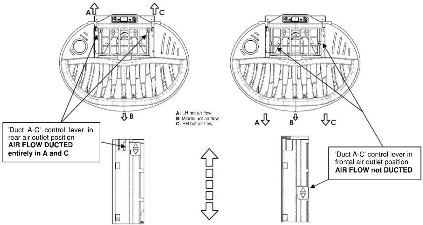
text_image
'Duct A-C' control lever in rear air outlet position AIR FLOW DUCTED entirely in A and C A : LH hot air flow B : Middle hot air flow C : RH hot air flow A : LH hot air flow B : Middle hot air flow C : RH hot air flow 'Duct A-C' control lever in frontal air outlet position AIR FLOW not DUCTED4.10 Idle period (end of season)
If the stove is not used for long periods, and/or at the end of each season, it is advisable to proceed as follows
- remove all the pellets from the hopper;
- disconnect the power and remove the power cable;
- clean thoroughly and, if necessary, have any damaged parts replaced by qualified personnel;
- protect the stove from dust with suitable covering;
- store in a dry and safe place protected from atmospheric agents.
5 STOVE CLEANING
Stove cleaning is very important to ensure correct operation and to prevent: blackening of the glass, poor combustion, deposits of ash and unburnt products in the brazier, reduced thermal efficiency.
The stove must only operate with the fire door closed.
The fire door seals must be checked periodically to prevent any air from entering; the combustion chamber and pellet duct work in a negative pressure and the fume exhaust in a positive pressure.
Routine cleaning is normally carried out by the customer following the instructions in the manual, whereas extraordinary maintenance, at least once a year, must be performed by the authorised Service Centre.

- Cleaning operations for all parts must be carried out with the stove unplugged and cold;
- Dispose of cleaning waste in accordance with the current local regulations;
- The stove must not be operated without its cladding;
- Avoid the creation of smoke and unburnt products during lighting and/or normal operation.
Given below are the control and/or maintenance operations for correct stove use and operation.
| Parts / Period Type of cleaning | 1 day routine cleaning | 2-3 days routine cleaning | 1 month routine cleaning | 2-3 months routine cleaning | 1 year extraordinary cleaning: carried out by the Service Centre |
| Brazier | ■ | ||||
| Ash compartment-pan | ■ | ||||
| Glass | ■ | ||||
| Baffle - fume exchanger | ■ ■ | ||||
| Manifold - fume extractor | ■ ■ | ||||
| Glass - door seal | ■ | ||||
| Pipe - flue connection | ■ |
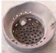
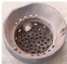
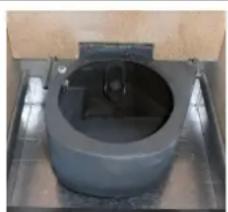
5.1 Cleaning the brazier
Remove the brazier and the ash deposited in the combustion chamber and brazier holder. A suitable vacuum cleaner may be used for this purpose. This operation must be carried out daily, especially in case of accumulated unburnt matter, to ensure perfect combustion conditions, since the brazier holes allow the flow of combustion air.
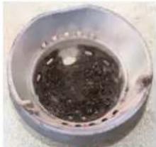
natural_image
Close-up of a circular metallic object with a dark central area and small protrusions, possibly a container or pot (no visible text or symbols)Brazier dirty
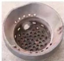
natural_image
Close-up of a perforated metal pipe or vent, no visible text or symbolsBrazier clean
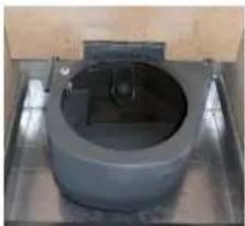
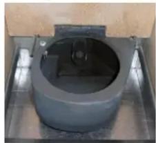
natural_image
Close-up of a cylindrical mechanical component mounted on a metal base (no visible text or symbols)Brazier Holder clean

The brazier must rest on the brazier holder and precisely on the entire ring band without air gaps.
5.2 Cleaning the ash container
The ash container is located directly under the brazier - brazier holder. To clean it, open the fire door and remove the ash and any combustion residuals using a suitable vacuum cleaner.
The door must be closed after cleaning. The ash container can be cleaned every 2-3 days depending on stove use.
5.3 Cleaning the glass and air slots
The glass can be cleaned using a damp cloth and specific non-abrasive detergents.
Special slots between the glass, glass stops and fire door at the top and bottom allow air to circulate on the inside surface of the glass. These slots must be kept clean of any deposits of ash and dust. Therefore periodically clean all around the the inner side of the glass.
5.4 Cleaning the fume extractor and combustion chamber
The combustion chamber must be cleaned at least once a year, removing all combustion residuals from the internal baffles and flueways. To do this, remove the cover and the top front panel of the stove. Remove the cast iron exchanger by undoing the fixing screws then clean the baffles and the chamber.
Also make sure to clean the fume extractor located under the chamber, accessed by removing the ash pan.
Every 3-4 months clean the inside walls (insulating-refractory) of the combustion chamber using suitable equipment (brushes) and replace them if necessary.
Every 1800 hours of operation, by means of a message 'SERVICE DUE', the stove signals the need for extraordinary maintenance (not under warranty) to be performed by qualified personnel who will carry out complete cleaning and reset the message.

Any knocking or forcing can damage the fume extractor, making it noisy during operation; therefore it is advisable to have this operation carried out by qualified personnel.
5.5 Cleaning the air flow meter
The air flow meter (it measures the flow of combustion air) installed inside the inlet pipe requires periodical internal cleaning every 3-4 months, using suitable equipment (blowing compressed air or suitable brushes).
5.6 Cleaning the ceramic surfaces (ceramic models)
The ceramic tiles are handicraft products and therefore may have minor surface imperfections such as tiny spots or slight colour differences. It is advisable to use a soft dry cloth to clean the ceramic surfaces; the use of detergents could highlight any flaws.
5.7 Cleaning the flue - flue connection
The flue connection must be cleaned at least once a year or whenever necessary depending on stove use and the type of installation.
Cleaning requires the suction and removal of the residuals in all the vertical and horizontal sections as well as the bends from the stove to the flue.
It is advisable to also clean the flue every year, to ensure correct and safe evacuation of fumes.

For any maintenance or end of season cleaning, COLA recommends contacting an authorised service centre, which will also check the wear on the stove's internal components.
6 MAINTENANCE
6.1 Introduction
Operations on the internal parts of the stove must be carried out by qualified personnel. Contact the nearest authorised service centre.

Make sure the stove is unplugged and cold before carrying out any work on it.
6.2 Removing the cladding

text_image
0.2 Removing the cladding 1 2 3 4 5 6 7 8 9Key:
1 - Ceramic cover
2 - Ceramic top front panel
3 - Ceramic bottom front panel
4 - Ceramic front side tiles
5 - Ceramic rear side tiles
6 - Bottom rear panel
7 - Top rear panel
8 - Side upright
9 - Pellet hopper door
6.3 Stove internal parts
text_image
Technical diagram of an electronic device with numbered components and directional arrows indicating assembly or flow.Key:
1 - Combustion chamber
2 - ELLISSE right-left supports
3 - Steel exchanger
4 - Vermiculite side walls
5 - Vermiculite upper baffle
6 - Vermiculite rear wall
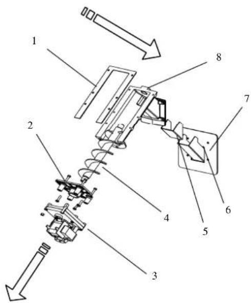
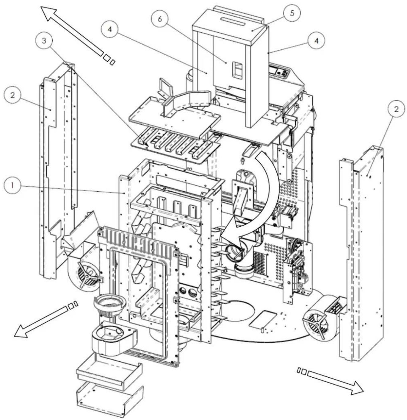
Exploded view of ELLISSE ductable stove combustion chamber and parts
Exploded views of:
1 - Brazier assembly
2 - Fume extractor assembly
3 - Auger assembly
text_image
Exploded view diagram of a mechanical assembly with numbered parts and directional arrow indicating motion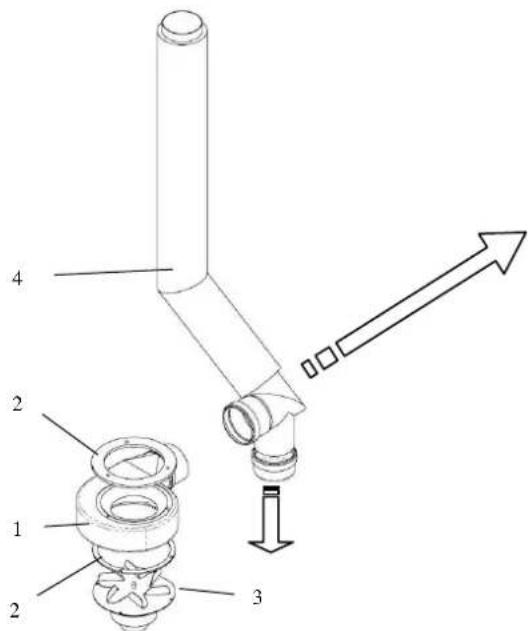
text_image
1 2 3 4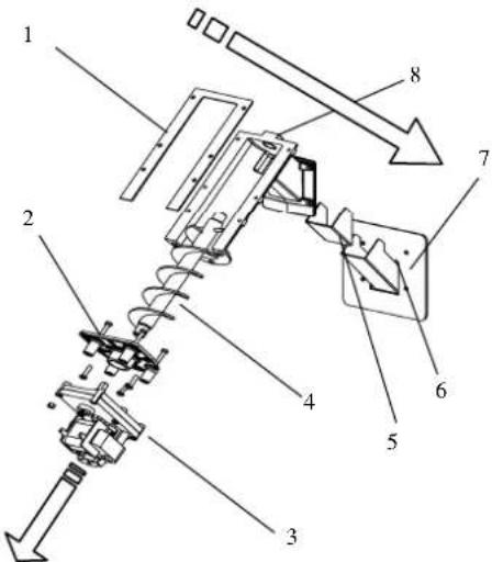
text_image
Technical diagram of a mechanical assembly with numbered components and directional arrows indicating motion or assembly.Key:
1 - Brazier
2 - Brazier holder
3 - Combustion air inlet pipe assembly
4 - Electrical element
5 - Brazier holder rear seal
6 - Suction unit front seal
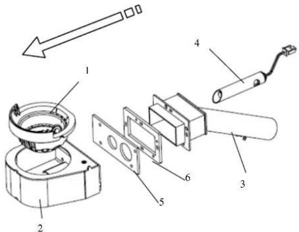
Key:
1 - Fume extractor volute
2 - Thermal seal
3 - Fume extractor motor
4 - Fume exhaust pipe
Key:
1 - Conveyor - hopper seal
2 - Gearmotor support flange
3 - Gearmotor
4 - Auger
5 - Seal for chute
6 - Pellet chute
7 - Conveyor-chamber seal
8 - Pellet conveyor
6.4 Electrical components
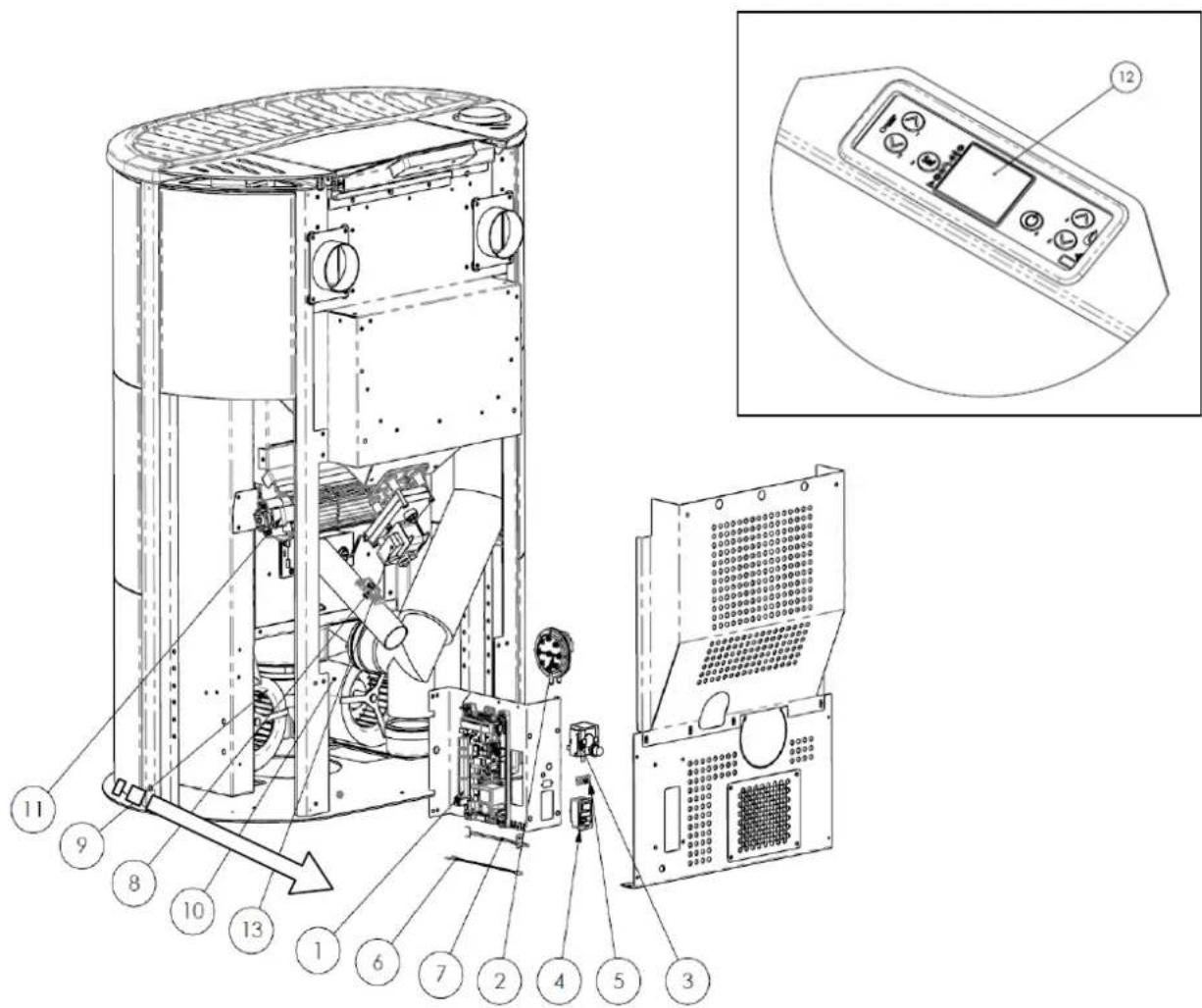
text_image
Technical diagram of an industrial machine with numbered components and a close-up of the control panel labeled 12.Key:
1 - Electronic board
2 - Control and safety vacuum switch
3 - Safety thermostat
4 - ON/OFF switch with fuses
5 - Serial connection port
6 - Room probe
7 - Fume probe
8 - Air flow meter
9 - Right centrifugal fan
10 - Left centrifugal fan
11 - Rear tangential fan
12 - Control panel model F047
13 - Auger control gearmotor
7 TROUBLESHOOTING
7.1 Alarm management
Alarms are indicated by an acoustic signal (if activated) and a message on the control panel.
In case of an alarm, shut down the stove, eliminate the cause and restart the stove according to the normal procedure described in this manual.
The alarms, with causes and cures, which can appear on the control panel are listed below:
| ALARMS - MESSAGES | |||
| Signalling Fault Possible causes Cures | |||
| AL 1 POWER FAILURE | -The stove does not start. | -No power during the lighting stage. | -Turn the stove OFF by pressing the button P4 and repeat the lighting procedure.-Other reinstatement operations must be carried out by a service centre. |
| AL 2 FUME PROBE | -Occurs in case of a fume temperature probe fault.-The shutdown procedure is activated. | -Faulty probe-The probe is disconnected from the board. | -Reinstatement operations must be carried out by a service centre. |
| AL 3 HOT FUMES | -Occurs if the fume probe detects a fume temperature above 280°C.-The shutdown procedure is activated. | -Faulty tangential fan.-No power to tangential fan.-Too many pellets. | -Adjust the pellet flow.-Other reinstatement operations must be carried out by a service centre. |
| AL 4 FAN FAIL | -Occurs when the exhaust fan is faulty.-The shutdown procedure is activated. | -The fume fan is blocked.-Faulty speed control sensor.-No power to fume fan. | -Reinstatement operations must be carried out by a service centre. |
| AL 5 NO IGNITION | -No flame in ignition stage.-The shutdown procedure is activated. | -The pellet hopper is empty.-The electrical element is faulty, dirty or not correctly positioned.-Pellet load setting incorrect. | -Check pellets in hopper.-Check the lighting procedures.-Other reinstatement operations must be carried out by a service centre. |
| AL 6 NO PELLETS | -Brazier not fed with pellets. | -The pellet hopper is empty.-The pellet feed gearmotor has to adjust.-The gearmotor does not feed pellets. | -Check pellets in hopper.-Adjust the pellet flow-Other reinstatement operations must be carried out by a service centre. |
| AL 7 THERMAL SAF | -Occurs in case of cutting in of auger duct temperature safety thermostat.-The system is stopped. | -The safety thermostat has detected a temperature above the setting threshold due to overheating of the bottom part of the hopper, blocking gearmotor operation. | -Check the cause of excessive overheating.-Reset the safety thermostat by pressing the reset button. |
| Signalling Fault Possible causes Cures | |||
| AL 8NO NEG PRESS | -In the work stage the stove detects a pressure below the vacuum switch setting threshold.-The system is stopped. | -The combustion chamber is dirty.-The fume duct is obstructed.-The fire door is not closed.-The overpressure valves are open-stuck.-Faulty vacuum switch. | -Check cleanness of the fume duct and combustion chamber.-Check hermetic closing of the door.-Check closing of the overpressure valves.-Other reinstatement operations must be carried out by a service centre. |
| AL 9INSUFF DRAUGHT | -Appears when the combustion air flow is below a certain threshold. | -The combustion chamber is dirty.-The fume duct is obstructed.-The fire door is not closed.-The overpressure valves are open-stuck.-Faulty air flow meter. | -Check cleanness of the fume duct and combustion chamber.-Check hermetic closing of the door.-Check closing of the overpressure valves.-Other reinstatement operations must be carried out by a service centre. |
| AL bAUG TRIAC ERROR | -Occurs when the gearmotor works continuously and for more than 60 sec.-The system is stopped. | -The controller detects a faulty gearmotor control relay (contacts stuck). | -Reinstatement operations must be carried out by a service centre. |
| WAITING COOL | -Occurs on relighting the stove immediately after having shut it down. | -Reset attempt in shutdown stage with stove hot in cooling stage. | -Alarm reset is possible only after shutdown. |
| AIR FLOW METER FAILURE | -Occurs when the air flow meter is disconnected. | -The controller does not detect the quantity of combustion air and does not shut down the stove; it only excludes the air flow meter functions. | -Reinstatement operations must be carried out by a service centre. |
| SERVICE DUE | -Occurs when the stove has exceeded 1800 hours of operation since the previous servicing. | -Extraordinary maintenance notice. | -Cleaning - extraordinary maintenance and reinstatement operations must be carried out by a authorised service centre. |
The Manufacturer reserves the right to make technical or aesthetic changes to the products at any time without notice. The drawings, measurements, diagrams and any other configurations are given only by way of example.
8 ENCLOSURES
CE MARKING INFORMATION
COLA
CE _13
1.4 Description technique
natural_image
Technical line drawing of a cylindrical industrial vessel or storage unit with internal compartments and structural supports (no text or symbols)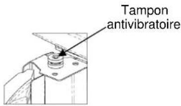
text_image
Tampon antivibratoireDÉTAIL A ÉCHELLE 1:2
Y
natural_image
Technical line drawing of a cylindrical industrial device with internal components and ventilation ducts (no text or symbols)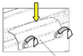
natural_image
Diagram showing a mechanical component with curved arrows indicating motion or force direction (no text or symbols)DÉTAIL A
ÉCHELLE 1:2
ARRÊT
2.3 Prise d'air
natural_image
3D diagram of a room interior with labeled components A, B, and C, showing airflow or ventilation paths (no text or symbols beyond labels)natural_image
Close-up of a computer control panel with buttons and dials (no visible text or symbols)text_image
D C B OFF i-3-1-01 PERiET- CHRONO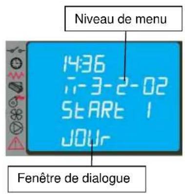
text_image
Niveau de menu 14:36 7-3-2-02 START 1 JOUy Fenêtre de dialoguetext_image
Diagram of a remote control panel with labeled buttons and indicator lightsnatural_image
Line drawing of a mobile phone case with four buttons and a keypad (no text or symbols)text_image
Diagram showing a vertical toolbar with icons and an arrow pointing to a black rectangle, likely indicating a function or direction.natural_image
Close-up of a circular metallic object with a dark central area and small protrusions, possibly a container or mold (no visible text or symbols)Brasier encrassé
natural_image
Close-up of a metallic cylindrical container with a perforated interior (no text or symbols visible)Brasier propre
natural_image
Close-up of a cylindrical mechanical component mounted on a metal base (no visible text or symbols)Support de brasier

text_image
Technical diagram of an electronic device with numbered components and directional arrows indicating assembly or operation.Légende :
text_image
Exploded view diagram of a mechanical assembly with numbered parts for identification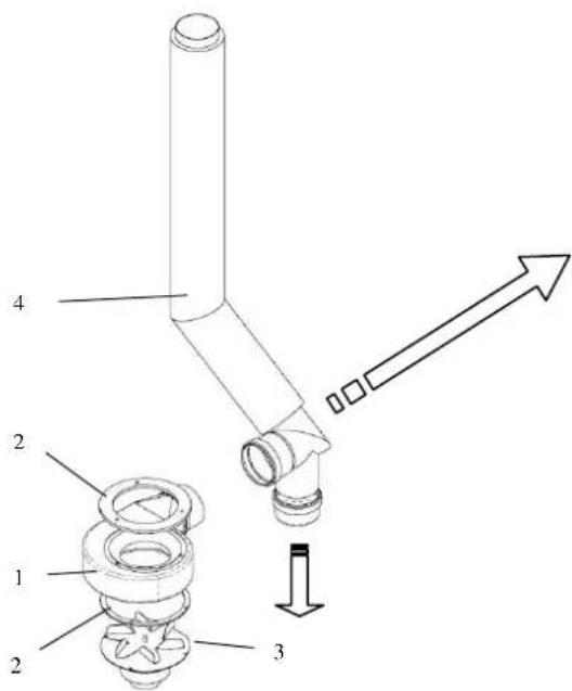
text_image
Technical diagram of a mechanical assembly with numbered components and directional arrow indicating motion or assembly.
text_image
Technical diagram of a mechanical assembly with numbered components and directional arrows indicating motion or assembly.Légende :
text_image
Technical diagram of a device with numbered components and an inset view of the control panel labeled 12.Légende :
INFORMATIONS RELATIVES AU MARQUAGE CE CE MARKING INFORMATION
COLA
CE
13
natural_image
Technical line drawing of a cylindrical industrial vessel or storage unit with internal compartments and mounting brackets (no text or symbols)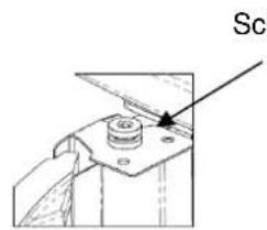
text_image
SclDETAIL A SKALA 1:2
Y
natural_image
Technical line drawing of a cylindrical industrial device with internal components and ventilation ducts (no text or symbols)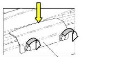
natural_image
Diagram showing two mechanical components with a yellow arrow pointing downward, no text or symbols presentDETAIL A SKALA 1:2
2.3 Lufteinlass
natural_image
3D architectural diagram of a room with labeled components A, B, C and directional arrows indicating movement or flow (no text or symbols beyond labels)natural_image
Close-up of a mechanical control panel with buttons and dials (no visible text or symbols)text_image
14:36 i-3-3-02 START 1 PROG-1 Dialogfenster| PROGRAMM 1 | |||
| Menüebene Auswahl | Bedeutung | Mögliche Werte | |
| 03-03-02 | START PROG 1 | Aktivierungsmuhrzeit | ora - OFF |
| 03-03-03 | STOP PROG 1 | Deaktivierungsmuhrzeit | ora - OFF |
| 03-03-04 | LUNEDI PROG 1 | Bezugstag | on/off |
| 03-03-05 | MARTEDI PROG 1 | on/off | |
| 03-03-06 | MERCOLEDI PROG 1 | on/off | |
| 03-03-07 | GIOVEDI PROG 1 | on/off | |
| 03-03-08 | VENERDI PROG 1 | on/off | |
| 03-03-09 | SABATO PROG 1 | on/off | |
| 03-03-10 | DOMENICA PROG 1 | on/off | |
| PROGRAMM 2 | |||
| Mendiebene Auswahl | Bedeutung | Mögliche Werte | |
| 03-03-11 | START PROG 2 | Aktivierungsmuhrzeit | ora - OFF |
| 03-03-12 | STOP PROG 2 | Deaktivierungsmuhrzeit | ora - OFF |
| 03-03-13 | LUNEDI PROG 2 | Bezugstag | on/off |
| 03-03-14 | MARTEDI PROG 2 | on/off | |
| 03-03-15 | MERCOLEDI PROG 2 | on/off | |
| 03-03-16 | GIOVEDI PROG 2 | on/off | |
| 03-03-17 | VENERDI PROG 2 | on/off | |
| 03-03-18 | SABATO PROG 2 | on/off | |
| 03-03-19 | DOMENICA PROG 2 | on/off | |
| PROGRAMM 3 | |||
| Menüebene Auswahl | Bedeutung | Möeliche Werte | |
| 03-03-20 | START PROG 3 | Aktivierungsahrzeit | ora - OFF |
| 03-03-21 | STOP PROG 3 | Deaktivierungshurzeit | ora - OFF |
| 03-03-22 | LUNEDI PROG 3 | Bezugstag | on/off |
| 03-03-23 | MARTEDI PROG 3 | on/off | |
| 03-03-24 | MERCOLEDI PROG 3 | on/off | |
| 03-03-25 | GIOVEDI PROG 3 | on/off | |
| 03-03-26 | VENERDI PROG 3 | on/off | |
| 03-03-27 | SABATO PROG 3 | on/off | |
| 03-03-28 | DOMENICA PROG 3 | on/off | |
| PROGRAMM 4 | |||
| Menüebene Auswahl | Bedeutung | Möeliche Werte | |
| 03-03-29 | START PROG 4 | Aktivierungsuhrzeit | ora - OFF |
| 03-03-30 | STOP PROG 4 | Deaktivierunesuhrzeit | ora - OFF |
| 03-03-31 | LUNEDI PROG 4 | Bezugstag | on/off |
| 03-03-32 | MARTEDI PROG 4 | on/off | |
| 03-03-33 | MERCOLEDI PROG 4 | on/off | |
| 03-03-34 | GIOVEDI PROG 4 | on/off | |
| 03-03-35 | VENERDI PROG 4 | on/off | |
| 03-03-36 | SABATO PROG 4 | on/off | |
| 03-03-37 | DOMENICA PROG 4 | on/off | |
text_image
Diagram of a remote control panel with labeled buttons and indicator lightsnatural_image
Line drawing of a mobile phone case with four buttons and a display screen (no text or symbols)natural_image
Simple line drawing of a rectangular container with an arrow pointing to the bottom side (no text or symbols)4.8 Thermostat - externer Uhrenthermostat
text_image
Vertical toolbar with icons including clock, gear, and directional symbols, plus an arrow pointing to a black rectangle.4.9 Heißluftgebläse
natural_image
Close-up of a circular container filled with dark granular substance, possibly a lid or container (no visible text or symbols)natural_image
Close-up of a metallic circular vent or drain with a perforated inner structure (no text or symbols visible)Brenntopf sauber
natural_image
Close-up of a dark cylindrical object with a central hole, possibly a container or tank, placed on a metallic surface (no visible text or symbols)text_image
Technical diagram of an electronic device with numbered components and directional arrows indicating assembly or operation.Zeichenerklärung:
text_image
Exploded view diagram of a mechanical assembly with numbered parts and directional arrow indicating direction
text_image
Technical diagram of a mechanical assembly with numbered components and directional arrow indicating motion or assembly.
text_image
Technical diagram of a mechanical assembly with numbered components and directional arrows indicating motion or assembly.Zeichenerklärung:
text_image
Technical diagram of a device with numbered components and an inset view of the control panel labeled 12.Zeichenerklärung:
CE MARKING INFORMATION
COLA
CE
natural_image
Technical line drawing of a cylindrical industrial vessel or storage unit with internal compartments and structural ribs (no text or symbols)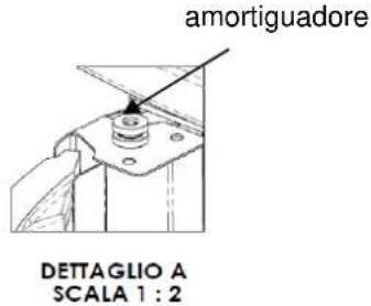
text_image
amortiguadore DETTAGLIO A SCALA 1 : 2Y
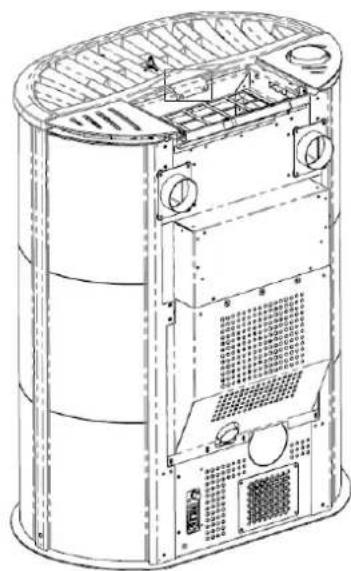
natural_image
Technical line drawing of a cylindrical industrial device with internal components and ventilation ducts (no text or symbols)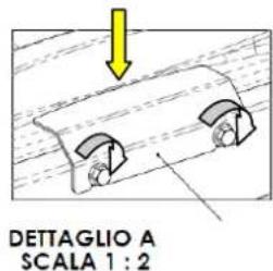
text_image
DETTAGLIO A SCALA 1 : 2Arrestos central
2.3 Toma de aire
natural_image
3D architectural diagram of a building interior with labeled components A, B, C and dimensions D, showing structural elements and directional arrows (no text or symbols beyond labels)natural_image
3D model of a computer tower with ventilation grilles and a door panel, no visible text or symbolstext_image
Vertical toolbar with icons and an arrow pointing to a black rectangle, likely indicating a function or measurement.natural_image
Close-up of a metallic cylindrical container with a dark inner layer and small circular indentations (no text or symbols visible)Brasero sucio
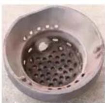
natural_image
Close-up of a metallic circular container with a perforated interior (no text or symbols visible)Brasero limpio
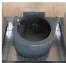
natural_image
Close-up of a cylindrical mechanical component mounted on a metal base (no visible text or symbols)Portabrasero limpio

text_image
Technical diagram of an internal combustion engine assembly with numbered components and directional arrows indicating flow or movement.Leyenda:
text_image
Exploded view diagram of a mechanical assembly with numbered parts for identification
text_image
Technical diagram of a mechanical assembly with numbered components and directional arrow indicating motion or force