VC450 E - Multimeter VOLTCRAFT - Free user manual and instructions
Find the device manual for free VC450 E VOLTCRAFT in PDF.
Download the instructions for your Multimeter in PDF format for free! Find your manual VC450 E - VOLTCRAFT and take your electronic device back in hand. On this page are published all the documents necessary for the use of your device. VC450 E by VOLTCRAFT.
USER MANUAL VC450 E VOLTCRAFT
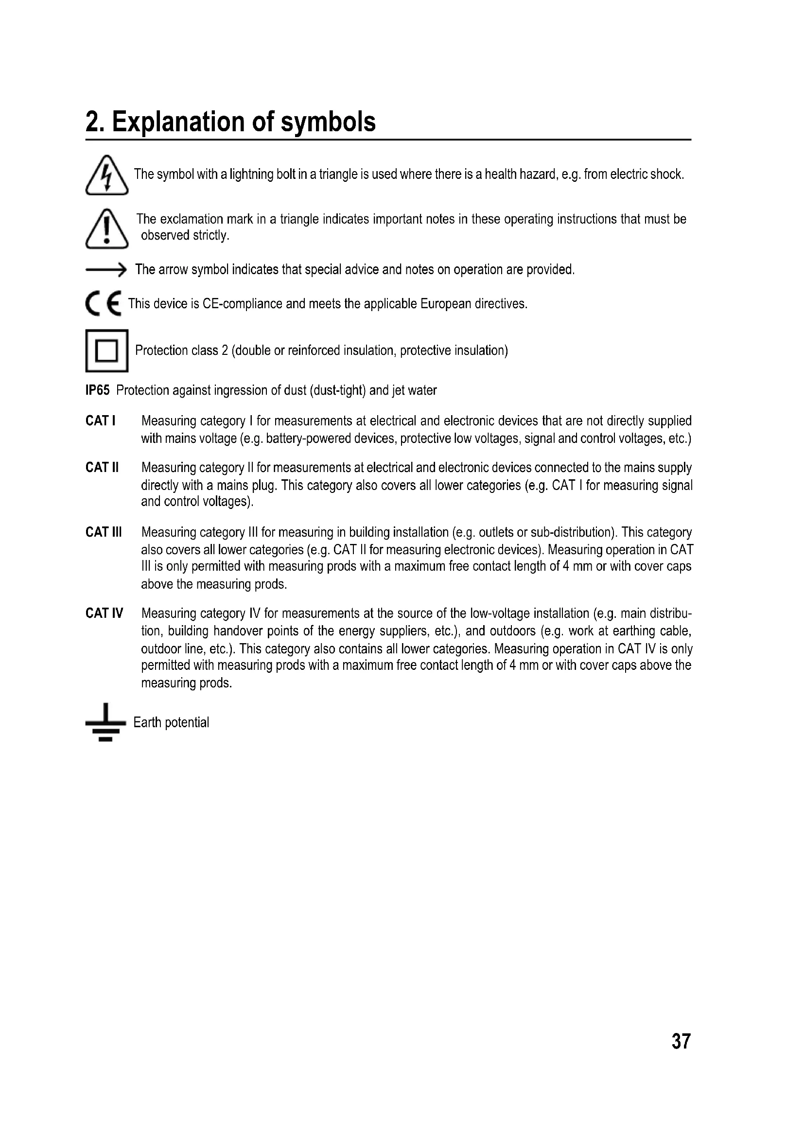
2. Explanation of symbols
The symbol with a lightning bolt in a triangle is used where there is a health hazard, e.g. from electric shock. The exclamation mark in a triangle indicates important notes in these operating instructions that must be observed strictly. The arrow symbol indicates that special advice and notes on operation are provided. This device is CE-compliance and meets the applicable European directives. Protection class 2 (double or reinforced insulation, protective insulation) IP65 Protection against ingression of dust (dust-tight) and jet water CAT I Measuring category I for measurements at electrical and electronic devices that are not directly supplied with mains voltage (e.g. battery-powered devices, protective low voltages, signal and control voltages, etc.) CAT II Measuring category II for measurements at electrical and electronic devices connected to the mains supply directly with a mains plug. This category also covers all lower categories (e.g. CAT I for measuring signal and control voltages). CAT III Measuring category III for measuring in building installation (e.g. outlets or sub-distribution). This category also covers all lower categories (e.g. CAT II for measuring electronic devices). Measuring operation in CAT III is only permitted with measuring prods with a maximum free contact length of 4 mm or with cover caps above the measuring prods. CAT IV Measuring category IV for measurements at the source of the low-voltage installation (e.g. main distribu- tion, building handover points of the energy suppliers, etc.), and outdoors (e.g. work at earthing cable, outdoor line, etc.). This category also contains all lower categories. Measuring operation in CAT IV is only permitted with measuring prods with a maximum free contact length of 4 mm or with cover caps above the measuring prods. Earth potential38
- Measuring and displaying electric parameters in the range of measuring category CAT III for up to 1000 V or CAT IV for up to 600 V against earth potential, pursuant to EN 61010-1 /UL 61010-1/CAN/CSA-C22.2 NO. 61010-1 and all lower categories.
- Measurement of direct current up to 1000 V
- Measurement of alternating current up to 1000 V
- Measurement of direct and alternating current up to 10 A or 20 A, short term (10 seconds)
- Frequency measurement from 600 Hz up to 40 MHz (electronic) or from 45 up to 400 Hz (electrical, as a subfunc- tion)
- Capacity measurement up to 60 mF
- Measurementofresistancesupto60MΩ
- Measurement of temperatures from -40 up to +1000 °C
- 3-Phase rotating direction display The measurement functions are selected using the dial switch. Automatic measurement range selection (autorange) is active in all measurement ranges (except mV, diode test and continuity test). In the AC voltage and AC current measurement range, true effective measured value (true root mean square; True RMS) up to a frequency of 400 Hz. Polarityisautomaticallyindicatedwiththeprex(-)ifthemeasuredvaluesarenegative. The two current measuring inputs are secured against overload with ceramic high-performance fuses. The voltage in the measuring circuit must not exceed 1000 V. The multimeter is operated with a conventional 9 V block battery (type 6F22, NEDA 1604 or same build). The device mustonlybeoperatedwiththespeciedbatterytype.Arechargeablebatteryshouldnotbeusedduetothelower capacity. Automatic deactivation switches off the device after approx. 15 minutes when no button has been pushed on the device. This prevents premature discharging of the battery. This function can be deactivated. There is an LED lamp that can be activated and used as a torch at the rear of the device. The multimeter must not be operated when it is open, i.e. with an open battery compartment or when the battery compartment lid is missing. Due to its build, the device corresponds to protection type IP65 and is dust- and water-jet-tight. The meter must not be used when wet or moist. Protection type IP65 only serves to protect the device. Measuring in potentially explosive areas (Ex) or damp rooms or under unfavourable ambient conditions is not permit- ted.Unfavourableambientconditionsare:Moistureorhighhumidity,dustandammablegases,fumesorsolvents, thunderstormsorthunderstormconditionslikestrongelectrostaticelds,etc. Forsafetyreasons,onlyusemeasuringlinesoraccessorieswhichareadjustedtothespecicationsofthemultimeter when measuring.39 The meter must only be operated by persons who are familiar with the required provisions for the measurement and the possible dangers. Use of personal protection equipment is recommended. Use other than that described above can lead to damage to the product and may involve additional risks such as, for example,shortcircuits,re,electricalshocketc.Nopartofthisproductmustbemodiedorconverted! Read the operating instructions carefully and keep them for later reference. Always observe the safety information!
4. Scope of delivery
- Type K thermal sensor with adapter
- 2x CAT IV safety test leads
- Operating instructions (on CD) Up-to-date operating instructions Download the latest operating instructions via the link www.conrad.com/downloads or scan the QR code. Follow the instructions on the website.40
5. Operating elements
A Spray-cast rubber protection B μA/mAmeasuringjack C A-measuring jack D COM measuring jack (reference potential, "Minus") E VΩmeasuringjack(withcommensurability"Plus") F Dial switch for selecting the measuring function G Function buttons H Display I Light sensor for display lighting J Suspension bracket, unfolding K LED Lamp L Measuring prod holder M Screws for battery and fuse compartment lid N Foldable standing bracket O Temperature measuring adapter (thermocouple socket on 4 mm banana plug)41
Read the operating instructions attentively and particularly observe the safety notes. If the safety notes and the information in these operating instructions regarding proper handling are not ob- served, we assume no liability for any resulting injury/property damage. In such cases, the war- ranty/guarantee will also lapse.
- Forsafetyandapprovalreasons,unauthorisedconversionand/ormodicationofthedevicearenot permitted.
- Consult an expert when in doubt as to the operation, safety or the connection of the device.
- Meters and accessories are not toys and have no place in the hands of children!
- In commercial institutions, the accident prevention regulations of the Employer’s Liability Insurance As- sociation for Electrical Systems and Operating Materials are to be observed.
- In schools, training centres, computer and self-help workshops, handling of meters must be supervised by trained personnel in a responsible manner.
- Ensure before every measurement that the meter is set to the proper measuring function.
- When using the measuring prods without cover caps, measurements between the meter and the earth potential must not be performed above the measuring category CAT II.
- When measuring in the measuring category CAT III and CAT IV, measuring prods with cover caps (max. 4 mm free contact length) must be used to avoid accidental short circuits during measurement. They are enclosed.
- The measuring prods have to be removed from the measured object every time the measuring function is changed.
- The voltage between the connection points of the meter and the earth potential must not exceed 1000 V DC/AC in CAT III or 600 V DC/AC in CAT IV.
- Be especially careful when dealing with voltages higher than 33 V alternating (AC) or 70 V direct volt- age (DC)! Even at these voltages it is possible to receive a potentially fatal electric shock if you touch electrical conductors.
- To avoid electric shock, make sure not to touch the connections/measuring points to be measured di- rectly or indirectly during measurement. During measuring, do not grip beyond the tangible grip range markings present on the measuring prods.
- Check the meter and its measuring lines for damage before each measurement. Never carry out any measurements if the protecting insulation is defective (torn, ripped off etc.). The enclosed measuring cables have a wear indicator. When they are damaged, a second insulation layer in a different colour becomes visible. The measuring accessories must no longer be used and must be replaced.
- Do not use the multimeter just before, during or just after a thunderstorm (lightning! / high-energy over- voltage!).Makesurethatyourhands,shoes,clothing,theoor,circuitsandcircuitcomponentsaredry.42
- Never operate the product in direct proximity of: - strongmagneticorelectromagneticelds - transmitter aerials or HF generators. This could affect the measurement.
- If you have reason to believe that the device can no longer be operated safely, disconnect it immediately and make sure it is not operated unintentionally. It can be assumed that safe operation is no longer possible if: - the device shows any visible damage, - the device no longer works and - the device was stored under unfavourable conditions for an extended period of time or - after it was exposed to extraordinary stress caused by transport.
- Do not switch the meter on immediately after it was taken from a cold to a warm environment. The condensation that forms might destroy your device. Allow the device to reach room temperature before switching it on.
- Do not leave the packaging material lying around carelessly since such materials can become dangerous toys in the hands of children.
- Also observe the safety information in each chapter of these instructions.43
7. Product description
The multimeter (referred to as DMM in the following) indicates measured values on the digital display. The measured value display of the DMM comprises 6000 counts (count = smallest display value). The AC measurement for voltage and current is performed as an effective median value (TrueRMS). If the DMM is not operated for approx. 15 minutes, it switches off automatically. This saves battery power and extends the period of operation. Automatic deactivation can be deactivate manually. The meter can be used for do-it-yourself or for professional and industrial applications up to CAT IV. The moulded-on rubber protection makes the device extremely robust, enabling it to survive even a fall from 2 m height. The device is also dust-tight and jet-water-protected (IP65). The rubber seal in the battery compartment must be checked for contamination at a battery or fuse change to ensure tightness. The seal must be clean at all times. Remove any contamination and particles with a thin cotton swab, etc. The seal must not be damaged. There may be transport protection caps in the angled plugs of the enclosed measuring lines. Remove them before pushing the plugs into the meter jacks. For better readability, the DMM can also be optimally mounted with the standing bracket on the rear. Dial switch (F) The individual measuring functions (measuring values) are selected via a dial switch.Theautomaticrangeselection“AUTO”isactiveformostmeasuringfunc- tions. The appropriate measurement range is set individually for each application. The dial switch has several functions in some areas. These subfunctions marked in red can be switched with the button “SELECT” (e.g. switching resistance measurement for continuity test or AC/DC switching etc.). Each push switches the function. Ifthemeterswitchissetto“OFF”,themeterisswitchedoff.Alwaysturnthemeter off when it is not in use.44
8. Display indications and symbols
The following symbols and information are present at the device or in the display. 1 True root mean square 2 Symbol for the diode test 3 Symbol for the acoustic continuity tester 4 Delta symbol for relative value measuring (= reference value measuring) 5 Symbol for milli (exp.-3) 6 Symbol for micro (exp.-6) 7 Volt (unit of electric voltage) 8 Ampere (unit of electric current) 9 Symbol for nano (exp.-9) 10 Symbol for milli (exp.-3) 11 Symbol for micro (exp.-6) 12 Farad (unit of electric capacity) 13 Symbol for mega (exp.6) 14 Symbol for kilo (exp.3) 15 Ohm (unit of electric resistance) 16 Hertz (unit of frequency) 17 Measured value display 18 Automatic lighting for display is active 19 Lockiconforphaserecognition(ashing=detectionmode,permanentdisplay=phaserecognised) 20 3-Phaserotatingdirectiondisplay“rightturning” 21 3-Phaserotatingdirectiondisplay“left-turning” 22 Symbol degrees Fahrenheit (Anglo-Saxon temperature unit) 23 Symbol Degrees Celsius (unit for the temperature) 24 Minimum value memory 25 Maximum value memory 26 Automatic measurement range selection is active 27 Battery level display 28 Automatic deactivation is activated 29 Hold function is active 30 Symbol for direct current ( ) 31 Polarityindicationforcurrentowdirection(minuspole) 32 Symbol for alternating current ( ) 33 Symbol for low impedance 34 Warning symbol for dangerous voltage or with warning sound when the measured value is exceeded45 REL Button for relative value measuring (= reference value measuring) SELECT Button for switching the subfunctions RANGE Button for manual measurement range selection MAX MIN Button for maximum and minimum value storage HOLD Button for manually capturing the currently measured value. OL Overload = the measurement range was exceeded OFF Switchposition“Meteroff” Lo.bt Battery change mandatory Symbol for the diode test Symbol for the acoustic continuity tester Symbol for the capacity measuring range °C°F Symbol for the temperature measurement range Degrees Celsius/degrees Fahrenheit (unit for the temperature) Symbol for alternating current Symbol for direct current COM Measuring connection reference potential mV Measuring function voltage measuring, Millivolt (exp.-3) V Measuring function voltage measuring, Volt (unit of electric voltage) A Measuring function current measuring, Ampere (unit of electric current) mA Measuring function current measuring, Milliampere (exp.-3) µA Measuring function current measuring, Microampere (exp.-6) Hz Measuring function frequency, Hertz (unit of frequency) Ω Measuringfunctionresistance,Ohm(unitofelectricalresistance) Motor Measuring function 3-phase rotating direction display Button to switch off the automatic lighting for the display Button for the LED lamp Symbol for the fuses used46
9. Measuring operation
Do not exceed the maximum permitted input values. Do not touch any circuits or parts of circuits if they may be subject to voltages higher than 33 V ACrms or 70 V DC! Danger to life! Before measuring, check the connected measuring lines for damage such as, for example, cuts, cracks or squeezing. Defective measuring lines must no longer be used! Danger to life! During measuring, do not grip beyond the tangible grip range markings present on the measuring prods. Only the two measuring lines that are required for measuring operation must be connected to the meter at any time. Remove all measuring lines not required from the meter for safety reasons. Measurements in electrical circuits >33 V/AC and >70 V/DC must only be carried out by specialists and technically instructed personnel who are familiar with the relevant regulations and the ensuing risks. If“OL”(overload)appearsonthedisplay,youhaveexceededthemeasurementrange. a) Switching on the meter Turnthedialswitch(F)tothecorrespondingmeasurementfunction.Toswitchoff,turnthedialswitchto“OFF”.Always turn the meter off when it is not in use. Before working with the meter, you have to insert the enclosed battery. Insertion and changing of the bat- teryisdescribedinthechapter“Cleaningandmaintenance”. b) Alternating voltage measurement “V/AC” Proceed as follows to measure alternating voltages “AC” (V ): - Turn the DMM on and select measuring function “V “.Thedisplayshows“AC”andtheunit“V”. - Plug the red measuring line into the V measuring jack (E) and the black measuring line into the COM measuring jack (D). - Connect the two measuring prods to the object to be meas- ured in parallel (generator, circuit, etc.). - The measured value is indicated on the display. - Remove the measuring lines from the object to be meas- ured after completion of the measurement and switch off the DMM. Thevoltagerange“V/AC”hasaninputresistance of≥10MΩ.Thiswillputbarelyanystrainonthe circuit.47 c) Direct voltage measurement “V/DC” Proceed as follows to measure direct voltages “DC” (V ): - Turn the DMM on and select measuring function “V “. - Press“SELECT”toswitchtothedirectcurrentmeasurementrange.The displayshows“DC”andtheunit“V”. - Plug the red measuring line into the V measuring jack (E) and the black measuring line into the COM measuring jack (D). - Connect the two measuring prods to the object to be measured in parallel (generator, circuit, etc.). The red measuring prod indicates the positive pole, the black measuring prod the negative pole. - The polarity of the respective measured value is indicated on the display together with the current measured value. - Remove the measuring lines from the object to be measured after completion of the measurement and switch off the DMM. Ifaminus“-”appearsinfrontofthemeasuredvaluefordirectvoltage,themeasuredvoltageisnegative (or the measuring lines are swapped). Thevoltagerange“V/DC”hasaninputresistanceof≥10MΩ.Thiswillputbarelyanystrainonthecircuit. d) LoZ alternating voltage measurement “V/AC” TheLoZmeasuringfunctionpermitsalternatingvoltagemeasurementwithlowimpedance(approx.300kΩ).The lower internal resistance of the meter reduces wrong measurement of scatter and phantom voltages. The measuring circuit is, however, subject to higher strain than with the standard measuring function. Proceed as follows to measure alternating voltages “AC “ (LoZ V ): - Turn the DMM on and select measuring function “LoZ V “.Thedisplayshows“LoZAC”andtheunit“V”. - Plug the red measuring line into the V measuring jack (E) and the black measuring line into the COM measuring jack (D). - Connect the two measuring prods to the object to be meas- ured in parallel (generator, circuit, etc.). - The measured value is indicated on the display. - Remove the measuring lines from the object to be meas- ured after completion of the measurement and switch off the DMM. Thevoltagerange“LoZV/AC”hasaninputresist- anceof<300kΩ.Thiswillputaslightstrainonthe circuit.48 e) Voltage measuring “mV” There is a dedicated measuring function to measure smaller voltages up to 600 mV at a high resolution. This function can be used for alternating and direct voltage alike. Proceed as follows to measure alternating voltages “AC “ (mV ): - Turn the DMM on and select measuring function “mV “.Thedisplayshows“AC”andtheunit“mV”. - Plug the red measuring line into the V measuring jack (E) and the black measuring line into the COM measuring jack (D). - Connect the two measuring prods to the object to be meas- ured in parallel (generator, circuit, etc.). - The measured value is indicated on the display. - Remove the measuring lines from the object to be meas- ured after completion of the measurement and switch off the DMM. Thevoltagerange“mV”hasaninputresistance of≥100MΩ.Withthemeasuringinputsopen,the high sensitivity may cause an undened meas- ured value to be displayed; however, this does not inuencethemeasuringresult. Proceed as follows to measure direct voltages “DC” (mV ): - Turn the DMM on and select measuring function “mV “. - Press“SELECT”toswitchtothedirectcurrentmeasurementrange.The displayshows“DC”andtheunit“mV”. - Plug the red measuring line into the V measuring jack (E) and the black measuring line into the COM measuring jack (D). - Connect the two measuring prods to the object to be measured in parallel (generator, circuit, etc.). The red measuring prod indicates the positive pole, the black measuring prod the negative pole. - The polarity of the respective measured value is indicated on the display together with the current measured value. - Remove the measuring lines from the object to be measured after comple- tion of the measurement and switch off the DMM. Ifaminus“-”appearsinfrontofthemeasuredvaluefordirectvolt- age, the measured voltage is negative (or the measuring lines are swapped). Thevoltagerange“mV”hasaninputresistanceof≥100MΩ.With the measuring inputs open, the high sensitivity may cause an un- denedmeasuredvaluetobe displayed;however,thisdoesnot inuencethemeasuringresult.49 f) Current measuring “A” Do not exceed the maximum permitted input values. Do not touch any circuits or parts of circuits if they may be subject to voltages higher than 33 V ACrms or 70 V DC! Danger to life! The voltage in the measuring circuit must not exceed 1000 V. Measuring >10 A must only be performed for max. 10 seconds and at 15 minute intervals. Never measure any currents above 20 A in the A range and no currents above 600 mA in the mA/µA range; otherwise the fuses trigger. Always start current measurements at the highest measurement range and switch down to lower ranges if necessary. Before connection of the meter and before measurement range changes, al- ways power down the circuit. All current measurement ranges are secured with fuses and thus protected against overload. Proceed as follows to measure direct currents (A ): - Turn the DMM on and select the required measuring function “A, mA, µA ”. - The table shows the different measuring functions and possible measuring ranges. Select your measuring function and the respective measuring jacks. Measuring function Measurement range Measuring jacks
A <10 A (<20 A) COM + A
mA <600 mA COM + µAmA µA <6000 µA COM + µAmA - Depending on your pre-selection, plug the red measuring lineintothemeasuringjack“A”(C)or“µAmA”(B).Plugthe blackmeasuringlineintothe“COM”(D)measuringjack. - Connect the two measuring prods in series with the object to be measured (battery, circuit, etc.) while powered down. The respective circuit must be opened for this. - Take the circuit into operation after connection. - The polarity of the respective measured value is indicated on the display together with the current measured value. - Power the circuit down again after the end of measuring and remove the measuring lines from the measured ob- ject. Switch off the DMM. Whenaminus“-”appearsinfrontofthemeasured value when measuring direct current, the current has the opposite direction (or the measuring lines have been swapped).50 Proceed as described above to measure alternating currents (A ). - TurntheDMMonandselectthedesiredmeasuringfunction“A,mA,µA”. - Press“SELECT”toswitchtotheACmeasuringrange.“AC”appearsinthe display. Pressing this button again takes you back to the DC measurement range, etc. - Connectthemeterasdescribedinchapter“Measuringdirectcurrents”. - Power the circuit down again after the end of measuring and remove the measuring lines from the measured object. Switch off the DMM. g) Resistance Measuring Make sure that all circuit parts, circuits and components and other objects of measurement are disconnected from the voltage and discharged. Proceed as follows to measure resistance: - TurntheDMMonandselectthemeasuringfunction“Ω”. - PlugtheredmeasuringlineintotheΩmeasuringjack(E) and the black measuring line into the COM measuring jack (D). - Check the measuring lines for continuity by connecting the two measuring prods. The impedance value must be approximately0-0.5Ω(inherentimpedanceofthemeas- uring lines). - Forlow-impedancemeasurements,pushthebutton“REL” (G) to not include the inherent impedance of the measur- ing lines in the following impedance measurement. The displayshows0Ω. - Now connect the two measuring prods to the object to be measured. As long as the object to be measured is not high-impedance or interrupted, the measured value will be indicated on the display. Wait until the displayed value has stabilised.Withimpedancesof>1MΩ,thismaytakeafew seconds. - If “OL” (overload) appears on the display,youhaveex- ceeded the measuring range or the measuring circuit is interrupted. - Remove the measuring lines from the object to be meas- ured after completion of the measurement and switch off the DMM. If you carry out a resistance measurement, make sure that the measuring points you touch with the meas- uring prods are free from dirt, oil, solderable lacquer or similar. Such circumstances can falsify the meas- ured result. Thebutton“REL”worksonlywhenameasuredvalueisdisplayed.When“OL”isdisplayed,thisfunction cannot be activated.51 h) Diode test Make sure that all circuit parts, circuits and components and other objects of measurement are disconnected from the voltage and discharged. - Turn the DMM on and select measuring function - Pressthe“SELECT”button2xtoswitchmeasurementfunc- tions. The display shows the diode symbol and the unit Volt (V). Pressing this button again takes you to the next measur- ing function, etc. - PlugtheredmeasuringlineintotheΩmeasuringjack(E)and the black measuring line into the COM measuring jack (D). - Check the measuring lines for continuity by connecting the two measuring prods. The value must be approximately 0,000 V. - Connect the two measuring prods with the object to be measured (diode). - Thedisplayshowsthecontinuityvoltage“UF”involt(V).If “OL” appears, the diode is measured in reverse direction (UR) or the diode is faulty (interruption). Perform a counter- pole measurement to check. - Remove the measuring lines from the object to be meas- ured after completion of the measurement and switch off the DMM.
Make sure that all circuit parts, circuits and components and other objects of measurement are disconnected from the voltage and discharged. - Turn the DMM on and select measuring function - Press the“SELECT”button1 x to switch measurement functions. The display shows the symbol for continuity testingandthesymbolfortheunit“Ω”.Pressingthisbutton again takes you to the next measuring function, etc. - PlugtheredmeasuringlineintotheΩmeasuringjack(E) and the black measuring line into the COM measuring jack (D). - Acontinuityvalueof≤10Ωisidentiedascontinuity;in this case a beep sounds. The measuring range is up to 600Ω. - If “OL” (overload) appearson the display,you have ex- ceeded the measuring range or the measuring circuit is interrupted. - Remove the measuring lines from the object to be meas- ured after completion of the measurement and switch off the DMM.52 j) Capacity measuring Make sure that all circuit parts, circuits and components and other objects of measurement are disconnected from the voltage and discharged. Always observe polarity with electrolyte capacitors. - TurntheDMMonandselectmeasuringfunction“Capacity” - PlugtheredmeasuringlineintotheΩmeasuringjack(E) and the black measuring line into the COM measuring jack (D). Due to the sensitive measuring input, the display mayshowavalueifthemeasuringlinesare“open”. Bypressingthebutton“REL”,thedisplayissetto “0”. The autorange feature is deactivated. This is recommended for small capacities in the nF range. - Connect the two measuring prods (red = plus/black = minus) with the object to be measured (capacitator). After a short time the display shows the capacity. Wait until the displayed value has stabilised. This may take a few seconds for ca- pacities of >40 µF. - If“OL”(overload)appearsonthedisplay,youhaveexceed- ed the measuring range. - Remove the measuring lines from the object to be measured after completion of the measurement and switch off the DMM. k) Frequency measurement (electronic) The DMM can be used to measure and indicate signal voltage frequencies from 600 Hz to 40 MHz. The maximum input range is 30 Vrms. This measuring function is not suitable for mains voltage measurements. Please observe the input values in the technical data. Formainsvoltagemeasurements,usetheadditionalfunction“Hz”inthecorrespondingvoltageandcurrent measurement ranges. Proceed as follows to measure frequencies: - TurntheDMMonandselectmeasuringfunction“Hz”.The displayindicates“Hz”. - Plug the red measuring line into the Hz measuring jack (E) and the black measuring line into the COM measuring jack (D). - Connect the two measuring prods to the object to be meas- ured in parallel (signal generator, circuit, etc.). - The frequency and corresponding unit are displayed. - Remove the measuring lines from the object to be meas- ured after completion of the measurement and switch off the DMM.53 l) Temperature measuring During temperature measurement, only the temperature sensor must be subject to the temperature to be measured. The meter working temperature must not be undercut or exceeded. Otherwise, there may be measuring errors. The contact temperature sensor must only be used at voltage-free surfaces. The meter contains a wire sensor that can measure up to temperatures of -40 to +230 °C. To use the full measurement range (-40 to +1000 °C) of the multimeter, optional type K thermal sensors are available. The enclosed adapter plug is required to connect type-K sensors with miniature plugs. Any type K thermal sensor may be used for temperature measurement. The temperature values can be displayed in °C or °F. For measuring temperatures, proceed as follows: - TurntheDMMonandselectmeasuringfunction“°C°F”. The display shows the unit °C for temperature measure- ment. - Connect the enclosed type-K-measuring adapter (O) to the V- and COM-measuring jacks in the correct polarity. The adapteronlytsontothemeterintheproperdirectionand will cover the current measuring jacks for safety. - Plug the enclosed temperature sensor into the measur- ing adapter in the correct polarity. The two contacts of the thermocouple are differently wide, to prevent wrong con- nection. - The display shows the temperature value in °C. - The“SELECT”buttoncanbeusedtoswitchtheunitfrom °C to °F. Every time you push the button, you switch the unit. - If “OL” appears on the display, themeasurement range has been exceeded or the sensor is interrupted. - After measuring, remove the sensor and turn off the DMM. m) 3-Phase rotating direction display “Motor” TheDMMmayidentifytherotatingdirectionina3-phasecurrentnetworkviathemeasuringfunction“Motor”.Only2 measuringlinesareneededtodisplaytherotatingdirection.Duringidentication,theouterconductorsL1,L2andL3 mustbescannedinsequence.TheDMMrecognisesthephaseoffsetandshowstherotatingdirection(rotatingeld) with an arrow subsequently. The 3-phase rotating direction display can be chosen only in the AC-V-range.54 Proceed as follows to identify the 3-phase rotating direction: - TurntheDMMonandselectmeasuringfunction“Motor”. Thedisplayshows“AC”andtheunit“V”. - Plug the red measuring line into the V measuring jack (E) and the black measuring line into the COM measuring jack (D). - Keepthebutton“SELECT”pressedforapprox.2seconds. Twobeepsareoutputandthelockicon(H19)willash. The automatic measuring range setting is deactivated and the 600 V-range is selected. The display will show approx.
- Connect the black measuring prod to the outer conductor L3. This connection remains unchanged throughout the test. Connect the red measuring prod to the outer conduc- tor L1. - Once the meter recognises two outer conductors, the nor- mal voltage will be displayed and the lock icon will remain lit. - Now switch the red measuring prod to outer conductor L2 within 5 seconds. If the time for measuring point change is exceeded, the DMM will interrupt the measurement and the function must be restarted. - The meter will evaluate the phase offset of the three sub- sequently determined outer conductors at correct measur- ing point change, and display the rotating direction via two symbols in the display. The arrow direction of the symbols shows the respective rotating direction: Clockwise = right turning Counter-clockwise = left-turning - Foranothermeasurementpushthebutton“SELECT”once briey.Todeactivatethefunction,keepthe“SELECT”but- ton pushed for at least 2 seconds. - Remove the measuring lines from the object to be meas- ured after completion of the measurement and switch off the DMM. Thefunctionbuttons“RANGE”,“MAXMIN”,“REL”,“Hz”and“HOLD”aredeactivatedinthismeasuring function and cannot be selected. When measuring 3 phase motor drives with variable frequency speed control interference can occur (PWM interference).Inordertominimizethisinterferencealongermeasuringtime(≥30s)isrequired. In this case, the nominal voltage indicated is only a reference value. The precision indicated is not valid for speed-controlled motor drives.55
10. Additional functions
The function buttons (G) can be used to activate various additional functions. Withthepushofthebutton,anacousticsignalisoutputforconrmation. a) SELECT Function Severalmeasuringfunctionsareassignedsubfunctions.Thesubfunctionsaremarkedred.Push“SELECT”toselect them. Every push will switch to the next subfunction. b) RANGE - Manual measurement range selection TheRANGEfunctionpermitsmanualsettingofaspecicmeasurementrange.Itispossiblethattheautomaticmeas- urement range setting will already select the next-higher measurement range or switch between ranges if the range is problematic. To suppress this, the measurement range can be set manually in some measuring functions. The manual measuring range setting works in all measuring functions, except: Motor, mV, continuity test and diode test. Pushingthe“RANGE”buttonwillcausethe“AUTO”symboltogooutandthedevicetoswitchtomanualmode. Eachpushofthe“RANGE”buttonswitchesthemeasurementrange;attheend,itwillstartwiththelowestmeasure- ment range again. The respective measurement range is indicated by the position of the decimal point. Toswitchoffthisfunction,keepthe“RANGE”buttonpressedforapprox.2seconds.The“AUTO”symbolappears and the automatic measurement range selection is active again. Switching the measuring function deactivates this function as well. c) MAX MIN Function This function permits saving and display of maximum or minimum values during a measuring series. Press the “MAX MIN”buttontoactivatethismeasuringfunction.Auto-rangeisdeactivated. With the active function, the minimum and maximum value of the current measuring series is saved at the same time. The max. and min. display can be switched at every push of a button (MAX MIN). The values are deleted after a measuring function change or when switching off the device. Todeactivatethefunction,keepthe“MAXMIN”buttonpushedforapprox.2seconds.Thedisplay“MAX”or“MIN” disappearsand“AUTO”appearsagain. This additional function cannot be activated in the measuring function “Motor” and “Hz”.56 d) REL Function The REL function allows a reference value measurement to avoid possible scatter displays or line loss as it occurs, e.g., during impedance measurements. For this purpose, the current indicated value is set to zero. A new reference value is set. Auto-range is deactivated. Pressthe“REL”buttontoactivatethismeasuringfunction.Thedisplayindicates“Δ”. Inordertoswitchoffthisfunction,pushthe“REL”buttonagainorchangethemeasurementfunction. This additional function cannot be activated in the measuring function “Motor” and “Hz”. e) Hz Function, frequency measurement (electrical) The AC voltage and current measurement ranges are occupied with subfunctions for frequency measurement. These measuring functions require a signal level of >30 Vrms and have a bandwidth of up to 400 Hz. They are therefore suitable for mains voltage. Tomeasurethefrequencyofthecurrentorvoltagesignal,pushthebutton“Hz”.Thedisplayshowsthefrequencyin Hz.Toswitchthedisplay,pushthebutton“Hz”again. f) HOLD Function The Hold function keeps the currently indicated measured value in the displays to allow you to read or record it easily. If you test live wires, make sure that this function is deactivated before the measurement starts. Otherwise, the measurement will be incorrect! This additional function cannot be activated in the measuring function “Motor” ToswitchontheHoldfunction,pushthe“HOLD”button;asignalsoundconrmsthiscommandand“H”appearson the display. InordertoswitchofftheHoldfunction,pushthe“HOLD”buttonagainorchangethemeasurementfunction. g) Display illumination The multimeter automatically recognises the brightness in the environment via a light sensor and switches on display lightingautomaticallywhentheDMMison.Thisautomaticfunctionisdisplayedbythesymbol“BL”.Itcanbedeacti- vated via the lighting button and remains deactivated until switched off via the dial switch. This automatic function is activated again at the next activation. h) LED lamp A white LED lamp (K) is integrated at the rear of the device. The lamp is switched on and off via the button with the torch icon. Every push of a button will switch the lamp on or off again. The lamp remains on until switched off manually via the button, until the meter is switched off via the dial switch (OFF) or the device is deactivated automatically after approx. 15 minutes.57
i) Automatic power-off
The DMM turns off automatically after approx. 15 minutes if no button or rotary switch is operated. This function protects the battery, saves battery power and extends the operating time. The active function is displayed with the symbol “ ”inthedisplay. The DMM emits 3 brief beeps approx. 1 minute before switching off. If the deactivation function is cancelled with any button (apart from the two lighting buttons) during this time, the next deactivation signal will sound after 15 minutes. Deactivation is signalled with a long beep. To reactivate the DMM after automatic deactivation:, use the dial switch or push any button (apart from the two lighting buttonsand“SELECT”). Automatic deactivation can be deactivate manually. Switchoffthemeter(OFF).Keepthebutton“SELECT”depressedandswitchontheDMMattherotarycontrol.The “ ”symbolisnotvisible.Automaticswitchingoffremainsinactiveuntilthemeteristurnedoffviatherotarycontrol.58
11. Cleaning and maintenance
a) General To ensure accuracy of the multimeter over an extended period of time, it should be cali- brated once a year. Apart from occasional cleaning and battery and fuse replacements, the meter requires no servicing. Notes on replacing the battery and fuse are provided below. Regularly check the technical safety of the device and measuring lines, e.g. check for damage to the casing or squeezing, etc. The rear of the device has holders with which the measuring lines can be at- tached to the meter. The measuring prods can be placed so that they are cleanly put away or at- tached higher to permit two-handed measurement. b) Cleaning Always observe the following safety information before cleaning the device: Live components may be exposed if covers are opened or parts are removed (unless this can be done without tools). The connected lines must be disconnected from the meter and all measuring objects before the device is cleaned or repaired. Switch off the DMM. Do not use any abrasive cleaning agents or petrol, alcohol or the like to clean the product. They will damage the surface of the meter. Furthermore, the fumes are hazardous to your health and explosive. Also do not use any sharp- edged tools, screwdrivers, metal brushes, etc. for cleaning. Use a clean, lint-free, antistatic, slightly damp cloth for cleaning the device or the display and the measuring lines. Allow the product to dry completely before you use it again to conduct measurements.59 c) Opening meter The casing design only permits access to the battery and fuse even when the battery and fuse compartment is opened. These measures improve user safety and operational comfort. Proceed as follows to open it: - Disconnect all measuring lines from the meter and switch it off. - Open the rear standing bracket (N). - Release the 5 rear battery compartment screws (M) with a matching screwdriver. - Pull the battery compartment lid (N) off of the meter with the standing bracket folded open. - The fuses and the battery compartment can be ac- cessed now. - After opening the battery compartment lid, always check the rubber seal around the battery and fuse compartment for contamination and clean it if neces- sary. This ensures protection against ingressing dust and water. - Close the casing again in the reverse order and screw the battery and fuse compartment closed. - The meter is ready for use once again. d) Fuse replacement The current measurement ranges are protected by high-performance fuses. If measuring in this range is no longer possible, you have to change the fuse. The fuses can be checked with the housing closed via the resistance measuring function. Select the meas- uringfunction“Ω”.Connectthemeasuringjack“Ω”(E)tothemAjack(B)ortheAjack(C)withameasuring line. The following measured values should be displayed if the fuses are intact: mA:<1.5MΩ,A:<5Ω.Whenahighervalueor“OL”isdisplayed,thefusemustbereplaced.60 Proceed as follows for fuse replacement: - Disconnect the connected measuring lines from the measuring circuit and the meter. Switch off the DMM. - Openthecasingasdescribedinchapter“OpeningMeter”. - Replace the defective fuse with a new fuse of the same type and rated current. The fuses have the following values: Fuse F1 F2 Characteristic Quick-acting Quick-acting Value FF600mA H 1000 V F11A H 1000V Dimension 6 x 32 mm 10 x 38 mm Type Ceramics Ceramics Item no. 442335 126357 - Close the casing again carefully. Using mended fuses or bridging the fuse holder is not permitted for safety reasons. It may cause resorarcexplosions.Neveroperatethemeterwhenitisopen. e) Inserting and changing the battery Operation of the meter requires a 9 V block battery (e.g. 1604A). You need to insert a new, charged battery before initial operation or when the battery change symbol appears on the display. The battery status is displayed via a dynamic icon. It changes appearance depending on battery status. When the emptysymbolashes,anewbatterymustbeinsertedtoavoidmeasuringerrors. The following symbols can be displayed: Battery full Battery nearly empty Battery empty Battery empty, meter switches off Proceed as follows to insert or change the batteries: - Disconnect the meter and the connected measuring lines from all measuring circuits. Remove all measuring lines from your meter. Switch off the DMM. - Openthecasingasdescribedinchapter“OpeningMeter”. - Replacetheatbatterywithanewoneofthesametype.Placeanewbatteryinthebatterycompartment,observing the correct polarity. - Close the casing again carefully.61 Never operate the meter when it is open. !DANGER TO LIFE! Donotleaveatbatteriesinthemeter.Evenbatteriesprotectedagainstleakingcancorrodeand thus release chemicals which may be detrimental to your health or destroy the device. Do not leave batteries lying around carelessly. They could be swallowed by children or pets. If swal- lowed, consult a doctor immediately. Remove the battery if the device is not used for extended periods of time to prevent leaking. Leaking or damaged batteries may cause alkali burns if they come in contact with the skin. There- fore, use suitable protective gloves. Makesurethatthebatteriesarenotshort-circuited.Donotthrowbatteriesintothere. Batteries must not be recharged or dismantled. Danger of explosion. You can order suitable alkaline batteries stating the following item no: Item no. 652509 (please order 1x). Only use alkaline batteries, as they are powerful and have a long service life.
a) General The product does not belong in the household waste. At the end of its service life, dispose of the product according to the relevant statutory regulations; e.g., returnittothecorrespondingcollectionofce. Remove any inserted batteries or rechargeable batteries and dispose of them separately from the product. b) Disposalofatbatteries You as the end user are required by law (Battery Ordinance) to return all used batteries/rechargeable batteries. Dis- posing of them in the household waste is prohibited! Rechargeable batteries containing harmful substances are marked with the following symbol, which points out that they are not allowed to be disposed of in the domestic refuse. The descriptions for the respective heavy metals are: Cd = cadmium, Hg = mercury, Pb = lead. You may return used rechargeable batteries freeofchargeattheofcialcollectionpointsofyourcommunity,inourstores,orwhereverrechargeable batteries are sold. Youthusfullthelegalrequirementsandmakeyourcontributiontoprotectingtheenvironment!62
In purchasing the DMM, you have acquired a product designed to the state of the art and operationally reliable. Nev- ertheless, problems or errors may occur. For this reason, the following is a description of how you can easily remove possible malfunctions yourself: Always observe the safety information! Error Possible cause Remedy The multimeter does not work. Is the battery dead? Check the status. Replace the battery. No measured value change. Is the wrong measuring function activated (AC/DC)? Check the display (AC/DC) and switch the function if required. Were the wrong measuring jacks used? Check the socket assignment or cor- rect seat of the measuring lines. Is the Hold function activated? Deactivate the Hold function. No measurement possible in the A measurement range Is the fuse of the A measuring range defective? Check the 11 A fuse F2. No measurement possible in the mA/µA measurement range Is the fuse of the mA/µA meas- urement range defective? Check the 600 mA fuse F1. Repairs other than those described above should only be carried out by an authorised specialist. If you have any questions about handling the meter, our technical support is available.63
Overload protection 1000 V *Up to 10 A permanent measurement, >10 - 20 A max. 10 s with measuring break of 15 minutes Alternate current A/AC Range Resolution Accuracy
Frequency range 40 - 400 Hz; Overload protection 1000 V Speciedmeasurementrange:5-100%ofthemeasuringrange When the measuring input is short-circuited, a display of 2 counts is possible *Up to 10 A permanent measurement, >10 - 20 A max. 10 s with measuring break of 15 minutes TrueRMScrestfactor(CF)≤3CFacrosstheentirerange TrueRMS crest factor for non-sine-shaped signals plus tolerance addition: CF >1.0 - 2.0 + 3% CF >2.0 - 2.5 + 5% CF >2.5 - 3.0 + 7%66 Resistance Range Resolution Accuracy 60.0Ω* 0.01Ω ±(1.3% + 3) 600.0Ω* 0.1Ω ±(1.3% + 3) 6.000kΩ 0.001kΩ ±(1.0% + 3)60.00kΩ 0.01kΩ 600.0kΩ 0.1kΩ 6.000MΩ 0.001MΩ ±(1.6% + 4) 60.00MΩ 0.01MΩ ±(3.0% + 7) Overload protection 1000 V Measuring voltage: approx. -0.5 V, measuring current approx. -0.7 mA *Accuracy after deduction of the measuring line resistance Capacity Range Resolution Accuracy
Signal level (without direct voltage share): ≤100kHz:200mV-30Vrms >100 kHz - <1 MHz: 600 mV - 30 Vrms ≥1MHz-<10MHz:1V-30Vrms 10 MHz -40 MHz: 1.8 V - 30 Vrms *The frequency measuring range starts at 600 Hz67 Frequency “Hz” (electrical, subfunction of A and V) Range Resolution Accuracy