VC850 - Multimeter VOLTCRAFT - Free user manual and instructions
Find the device manual for free VC850 VOLTCRAFT in PDF.
Download the instructions for your Multimeter in PDF format for free! Find your manual VC850 - VOLTCRAFT and take your electronic device back in hand. On this page are published all the documents necessary for the use of your device. VC850 by VOLTCRAFT.
USER MANUAL VC850 VOLTCRAFT
These operating instructions belong with this product. They contain important information for putting it into service and operating it. This should be noted also when this product is passed on to a third party. Therefore look after these operating instructions for future reference! A list of contents with the corresponding page numbers can be found in the index on page 30.
- Introduction Dear Customer, Thank you for making the excellent decision of purchasing this Voltcraft® product. You have acquired a quality product from a brand family which has distinguished itself in the fields of measuring, charging and network technology thanks to its particular expertise and its permanent inno- vation. With Voltcraft®, you will be able to cope even with difficult tasks as an ambitious hobbyist or as a pro- fessional user. Voltcraft® offers reliable technology and a great price-performance-ratio. We are positive: starting to work with Voltcraft will also be the beginning of a long, successful relationship. Enjoy your new Voltcraft® product!30 Table of Contents Introduction p. 29
- Intended Use p. 31
- Operating Elements p. 32
- Safety Notices p. 33
- Product Description p. 35
- Scope of Delivery p. 36
- Display Indications and Symbols p. 36
- Measuring p. 37
- a) Switching on the Multimeter p. 38
- b) Voltage Measuring “V” p. 38
- c) Current Measuring “A“ p. 39
- d) Frequency Measuring p. 40
- e) Resistance Measuring p. 40
- f) Diode Test p. 41
- g) Continuity Check p. 42
- h) Capacity Measuring p. 42
- i) Temperature Measuring (VC850 only) p. 43
- RANGE Function, Manual Measurement Range Selection p. 43
- REL Function p. 44
- HOLD Function p. 44
- Low imp. 400 kΩ Function p. 44
- RS232 Interface p. 45
- Display Illumination p. 45
- Hz% Sub Function p. 45
- Cleaning and Maintenance p. 46
- General Information p. 46
- Cleaning p. 46
- Opening meter p. 46
- Checking the Fuse/Replacing the Fuse p. 47
- Inserting/changing the batteries p. 48
- Disposal p. 49
- Troubleshooting p. 50
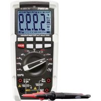
- Technical Data Intended Use - Measuring and displaying electric parameters in the range of overvoltage CAT IV (up to max. 600V or CAT III up to max.1000 V against ground potential, pursuant to EN 61010-1) and all lower categories. - Measurement of direct and alternating voltages up to a maximum of 1,000 V/DC/, 750 V/AC - Measurement of direct and alternating current up to 10 A - Frequency measurement up to 10 MHz - Capacity measuring up to 4000 µF - Measuring resistance values of up to 60 MΩ - Continuity check (< 30 Ω acoustic) - Diode test - Temperature measuring from –40 to + 1,000 °C (only VC850) The measurement functions are selected using the rotary switch. The measuring range is selected auto- matically for all measuringfunctions (except for diode and continuity tests). Manual setting is possible at any time. The VC850 shows actual effective measured values (True RMS) in the voltage and current measuring area. For VC830, the average value (RMS Sinus) is displayed. Polarity is displayed automatically. The two current measuring inputs are secured against overload. The voltage in the current measuring circuit must not exceed 1,000 V category III or 600 V in category IV. The two current measuring ranges are protected by ceramic high-performance fuses. A low-impedance function (low imp) enables measuring with reduced internal resistance. This suppres- ses phantom voltages that may appear in high-ohm measurements. Measuring with reduced impedance is only permitted for measuring circuits of up to 1,000 V and for up to 3 s. When pressing the low imp but- ton, you can hear a signal sound, and there will be a warning shown in the display. The multimeter is operated with a common 9 V alkaline battery block. The device may only be operated with the specified batteries. The multimeter must not be operated when it is open, i.e. with an open battery compartment or when the battery compartment cover is missing. The patented protection device does not permit the battery and fuse lids to be opened when the measuring lines are inserted into the measuring jacks. Similarly, inser- ting the measuring lines is prevented when the battery and fuse lids are open. Measuring in damp rooms or under unfavourable ambient conditions is not permitted. Unfavourable ambient conditions are: - Wetness or high air humidity - Dust and flammable gases, vapours or solvent, - Thunderstorms or similar conditions such as strong electrostatic fields etc. For safety reasons, only use measuring cables or accessories which are adjusted to the specifications of the multimeter when measuring. Any use other than the one described above damages the product. Moreover, this involves dangers such as e.g. short circuit, fire, electric shock, etc. No part of the product must be modified or rebuilt! Read the operating instructions carefully and retain them for later reference. The safety instructions must be observed at all times.32 Operating Elements See fold-out page 1 Spray-cast rubber protection 2 Display 3 SELECT button for function switching (red symbols) 4 Rotary switch for selecting the measuring function 5 mAµA measuring jack 6 10 A measuring jack 7 HzVΩ capacity measuring jack (with commensurability “Plus”) 8 COM measuring jack (reference potential, “Minus”) 9 Low Imp. 400 kΩ button only for switching impedance 10 Function Buttons RANGE: Manual measurement range switching REL/PC: REL = Reference value measurement, PC = Activates interface Hz/% Function switch (yellow icons, only active in the AC measuring ranges) H/LIGHT: Hold function for holding the measuring display, adding the display lighting 11 Optically isolated RS232 interface 12 Stand connection thread 13 Foldable mounting brackets 14 Battery compartment 15 Screw for battery and fuse compartment 16 Fuse compartment33 Safety Notices p. 5131
Please read the entire operating instructions before using the product for the first time; they contain important information about the correct operation. The guarantee/warranty will be void if damage is incurred resulting from non- compliance with the operating instructions. We will not assume any responsibi- lity for consequential damage! We do not assume any liability for material and personal damage caused by improper use or non-compliance with the safety instructions! In such cases the warranty/guarantee is void. This device left the manufacture’s factory in a safe and perfect condition. We kindly request that you as a user observe the safety instructions and warnings contained in this ope- rating manual to preserve this condition and to ensure safe operation! Please pay attention to the following symbols:
An exclamation mark in a triangle shows important information in this user’s manual that has to be observed.
The triangle containing a lightning symbol warns of danger of an electric shock or of the impairment of the electrical safety of the device.
The “hand” symbol informs you that there are special tips and hints concerning the operation. This product has been CE-tested and meets the necessary European guidelines. Class 2 insulation (double or reinforced insulation) CAT II Overvoltage category II for measurements on electric and electronic devices connec- ted to the mains supply with a power plug. This category also covers all smaller cate- gories (e.g. CAT I for measuring signal and control voltages). CAT III Overvoltage category III for measuring in building installation (e.g. outlets or sub-distri- bution). This category also covers all smaller categories (e.g. CAT II for measuring electronic devices).34 CAT III Overvoltage category IV for measuring at the source of the low-voltage installation (e.g. main distribution, house-transfer points of energy providers, etc.) This category also contains all lower categories. Ground potential For safety and licensing reasons (CE), unauthorised conversion and/or modification of the device is not permitted. Consult an expert when in doubt as to the operation, the safety or the connection of the device. meters and accessories are not toys and have no place in the hands of children. On industrial sites, the accident prevention regulations of the association of the industrial workers’ society for electrical equipment and utilities must be followed. In schools, training centres, computer and self-help workshops, handling of meters must be supervised by trained personnel in a responsible manner. Before measuring voltages, always make sure that the meter is not set to a measuring range for cur- rents. The voltage between the connection points of the measuring device and the ground potential must not exceed 1,000 V DC/AC in CAT IV III or 600 V CAT IV. The measuring prods have to be removed from the measured object every time the measuring range is changed. Be especially careful when dealing with voltages higher than 25V AC or 35 V DC. Even at these voltages it is possible to receive a fatal electric shock if you touch electrical conductors. Check the measuring device and its measuring lines for damage before each measurement. Never carry out any measurements if the protecting insulation is defective (torn, ripped off etc.) To avoid electric shock, do not to touch the connections/measuring points directly or indirectly during measu- rements. During measuring, do not grip beyond the grip range markings (which you can feel) present on the measuring prods. Do not use the multimeter just before, during or just after a thunderstorm (lightning! / high-energy over- voltage!). Please make sure that your hands, your shoes, your clothing, the floor, switches and switching components are dry. Avoid an operation near: - strong magnetic or electromagnetic fields - transmitter aerials or HF generators, This could affect the measurement.35 If you have reason to assume that safe operation is no longer possible, disconnect the appliance imme- diately and secure it against inadvertent operation. It can be assumed that safe operation is no longer possible if: - the device shows visible damage, - the unit does not operate any longer and - the unit was stored under unfavourable conditions for a long period of time or - after it was exposed to extraordinary stress caused by transport. Do not switch the meter on immediately after it has been taken from a cold to a warm environment. The condensation that forms might destroy your device. Allow the device to reach room temperature before switching it on. Do not leave the packaging material lying around carelessly since such materials can become dange- rous toys in the hands of children. You should also heed the safety instructions in each chapter of these instructions. Product Description The multimeter (referred to as DMM in the following) indicates measured values on the digital display. The measuring value display of the DMM comprises 6000 counts (count = smallest display value). The meter can be used for do-it-yourself or for professional applications. For better readability, the DMM can also be optimally mounted with the clip on the rear. The battery and fuse compartment can only be opened when all measuring lines were removed from the meter. When the battery and fuse compartment is opened, the measuring lines cannot be inserted into the measuring jacks. This improves user safety. In the voltage and current measurement area, a warning sound and a flashing “WARNING!” signal is used to announce wrongly connected measuring lines. Connect the measuring lines correctly before measuring. Rotary switch (4) The individual measuring functions are selected via a rotary switch. The automatic range selection “auto range” is active. The appropriate range of measurement is set individually for each application. Always start current measurements at the highest measurement range (10 A) and switch down to lower ranges if necessary. If the multimeter switch is set to “OFF”, the meter is switched off. Always turn the device off when it is not in use. The figure shows the alignment of the measuringfunctions of VC830 and VC850.36 Scope of Delivery Multimeter with spay-cast rubber protection 9V block battery Safety measuring cable Software CD Operating instructions Display Indications and Symbols The symbols and indications are different for each model. This is a summary of all possible symbols and information of the VC800 series. Delta symbol for relative value measuring (= reference value measuring) Auto range stands for “automatic measuring range selection” H Data-Hold function is active OL Overload = the measuring range was exceeded OFF Switch position “off” Battery replacement symbol; please replace the batteries immediately to avoid mea- suring errors! Symbol for the diode test Symbol for the acoustic continuity tester AC Alternating current for voltage and current DC Direct current for voltage and current mV Millivolt (exp.–3) V Volt (unit of electric potential difference or voltage) A Ampere (unit of electric current) mA Milliampere (exp.–3) µA Microampere (exp.-6) Hz Hertz (unit of frequency) kHz Kilo Hertz (exp.3) MHz Mega Hertz (exp.6) % Duty-Cycle, shows the ratio of the positive half half-wave in percent °C Degrees Celsius °F Degrees Fahrenheit Ω Ohm (unit of electric impedance) kΩ Kilo Ohm (exp.3)37 MΩ Mega Ohm (exp.6) nF Nanofarad (unit of electric capacity, exp.-9, symbol ) µF Microfarad (exp.-6) Symbol for the capacity measuring range WARNING! Warning symbol for voltages >30 V AC/DC, Low imp function and wrongly connected measuring lines Symbol for data transfer (active RS232 interfaces) Bar graph (only for V, A, Ω) Symbol for the integrated fuses Measuring
Do not exceed the maximum permitted input values. Do not touch any circuits or parts of circuits if there could be voltages higher than 25 V ACrms or 35 V DC present within them. Danger to life! Before measuring, check the connected measuring lines for damage such as, for example, cuts, cracks or squeezing. Defective measuring cables must no longer be used. Mortal danger! During measuring, do not grip beyond the tangible grip range markings present on the test prods. Measuring is only permitted when the battery and fuse compartment is closed. When the compartment is open, all measuring jacks are mechanically secured against insertion.
You may only connect the two measuring lines to the measuring device that are required for measuring operation. Remove all measuring lines not required from the device for safety reasons. Measurements in electrical circuits >50 V/AC and >75 V/DC must only be carried out by specialists and technically instructed personnel who are familiar with the relevant regulations and the ensuing risks.
As soon as “OL” (overload) appears on the display, you have exceeded the measuring range.38 a) Switching on the Multimeter The multimeter can be turned on and off using the rotary switch. Turn the rotary switch (4) to the corre- sponding measurement function. To switch off turn the rotary switch to “OFF”. This can be reached on both sides of the turning range. Always turn the device off when it is not in use.
Prior to working with the meter, you have to insert the enclosed battery. Insertion and changing of the battery is described in the “Cleaning and Maintenance” chapter. b) Voltage Measuring “V” Proceed as follows to measure DC voltages (V ): - Turn the DMM on and select measuring range “V ”. - Plug the red measuring line into the V measuring jack and the black measuring line into the COM measuring jack (8). - Now connect the two measuring prods to the object to be measured (battery, switch etc.). The red measuring tip indicates the positive pole, the black measuring tip the negative pole. - The polarity of the respective measured value is indica- ted on the display together with the current measured value.
As soon as a minus “-” appears for the direct voltage in front of the measuring value, the measured voltage is negative (or the measuring tips have been mixed up). The voltage range “V DC/AC” shows an input resistance of >10 MOhm. - After measuring, remove the measuring lines from the measured object and turn the DMM off. Proceed as follows to measure AC voltages (V ): - Turn the DMM on and select measuring range “V ”. Press “SELECT” (3) to switch to the AC mea- suring range at the VC850. “AC” appears in the display. - Plug the red measuring line into the V measuring jack (7) and the black measuring line into the COM measuring jack (8). - Now connect the two measuring prods to the object to be measured (generator, switch etc.). - The measuring value is indicated on the display - After measuring, remove the measuring lines from the measured object and turn the DMM off.39 c) Current Measuring “A“
Do not exceed the maximum permitted input values. Do not touch any circuits or parts of circuits if there could be voltages higher than 25 V ACrms or 35 V DC present within them. Danger to life! The voltage in the measuring circuit may not exceed 1,000 V in CAT III. Measuring >5 A may only be performed for max. 10 seconds and at 10 minute intervals.
Always start current measurements at the highest measurement range and switch down to lower ranges if necessary. Before changing the measurement range, always shut off the circuit. All current measuring ranges are secured with fuses and thus pro- tected against overload. Proceed as follows to measure DC voltages (A ): - Turn the DMM on and select measuring range “A ”. - The table shows the different measuring functions and possible measuring ranges. Select your measuring range and the respective measuring jacks. Measuring VC830, VC850 Measuring function jacks µA 0.1 µA - 6000 µA COM + mAµA mA 0.01 mA - 600 mA COM + mAµA
10A 0.001 A - 10 A COM + 10A
- Insert the red measuring line into the mA µA or 10A measuring jack. Plug the black measuring line into the COM socket. - Now connect the two test prods in series with the object to be measured (battery, circuit etc.); the display indica- tes the polarity of the measured value together with the currently measured value.
When a minus “-” appears in front of the measured value when measuring DC, the measured voltage is negative (or the measuring lines have been mixed up). - After measuring, remove the measuring lines from the measured object and turn the DMM off. Proceed as described above to measure alternating currents (A ). - Turn the DMM on and select measuring range “A ”. Press “SELECT” (3) to switch to the AC mea- suring range at the VC850. “AC” appears in the display. Pressing this button again, takes you back etc. - After measuring, remove the measuring lines from the measured object and turn the DMM off. Do not measure any currents above 10 A in the 10A range and no currents above 600 mA in the mA/µA range, otherwise the fuses trigger.
d) Frequency Measuring The DMM can be used to measure and indicate signal voltage frequencies from 0.001 Hz to 10 MHz. Proceed as follows to measure frequencies: - Turn the DMM on and select measuring range “Hz”. The display reads “Hz”. - Plug the red measuring line into the Hz measuring jack and the black measuring line into the COM measuring jack (8) . - Now connect the two measuring prods to the object to be measured (signal generator, switch etc.). - The frequency and corresponding unit are displayed. - After measuring, remove the measuring lines from the measured object and turn the DMM off. e) Resistance Measuring
Make sure that all the circuit parts, switches and components and other objects of measurement are disconnected from the voltage and discharged. Proceed as follows to measure the resistance: - Turn the DMM on and select measuring range “Ω”. - Plug the red measuring line into the Ω measuring jack and the black measuring line into the COM measuring jack (8) . - Check the measuring lines for continuity by connecting both measuring prods with one another. The resistance value must be approximately 0 - 1.5 Ohm (inherent resi- stance of the measuring lines). - For low-impedance measurements, press the button “REL” (10) to not let the inherent resistance of the measu- ring lines flow into the following resistance measuring. The display shows the delta symbol and 0 Ohm are indi- cated. The automatic range selection (auto range) is inac- tive. - Now connect the measuring prods to the object to be measured. As long as the object to be measured is not high-Ohm or interrupted, the measured value will be indicated on the display. Wait until the displayed value has stabilised. With resistances of >1 MOhm, this may take a few seconds.41 If “OL” (overload) appears on the display, you have exceeded the measuring range or the measuring cir- cuit has been broken. Pressing the “REL” button again switches off the relative function and activates the auto range function. - After measuring, remove the measuring lines from the measured object and turn the DMM off.
If you carry out a resistance measurement, make sure that the measuring points you touch with the test prods are free from dirt, oil, solderable lacquer or the like. Such cir- cumstances can falsify the measured result. f) Diode Test
Make sure that all the circuit parts, switches and components and other objects of measurement are disconnected from the voltage and discharged. - Turn the DMM on and select measuring range
The diode symbol appears in the display. - Plug the red measuring line into the Ω measuring jack and the black measuring line into the COM measuring jack (8) . - Check the measuring lines for continuity by connecting both measuring prods with one another. The value must be approximately 0.000 V. - Now connect the two measuring prods with the object to be measured (diode). - The display shows the continuity voltage “UF” in volt (V). If “OL” appears, the diode is measured in reverse direc- tion (UR) or the diode is faulty (interruption). Perform a counter-pole measurement to check. - After measuring, remove the measuring lines from the measured object and turn the DMM off.42 g) Continuity Check
Make sure that all the circuit parts, switches and components and other objects of measurement are disconnected from the voltage and discharged. - Turn the DMM on and select measuring range
Press “SELECT” button to switch measurement functions. The symbol for continuity check now appears in the display. Pressing this button again takes you to the first measu- ring function etc. - Plug the red measuring line into the Ω measuring jack and the black measuring line into the COM measuring jack (8) - A continuity value of less than 30 Ohm is identified as continuity; in this case a beep sounds. - As soon as “OL.” (overload) appears on the display, you have exceeded the measuring range or the measuring circuit has been interrupted. - After measuring, remove the measuring lines from the measured object and turn the DMM off. h) Capacity Measuring
Make sure that all the circuit parts, switches and components and other objects of measurement are disconnected from the voltage and discharged. With electrolyte capacitors, ensure that you observe the polarity. - Turn the DMM on and select measuring range - Plug the red measuring line into the V measuring jack and the black measuring line into the COM measuring jack (8) . - The display shows the unit “nF”.
Due to the sensitive measuring input, the display may show a value in case of “open” measuring lines. By pressing the button “REL”, the display is set to “0”. The Auto range function remains active. - Now connect the two test prods (red = positive pole/black = negative pole) with the object to be measured (conden- ser). After a short while the display shows the capacity. Wait until the displayed value has stabilised. With capaci- ties of >40 µF, this may take a few seconds. - If “OL” (overload) appears on the display, you have exceeded the measuring range. - After measuring, remove the measuring lines from the measured object and turn the DMM off.43
During temperature measurement, only the temperature sensor must be subject to the the temperature to be measured. The meter working temperature must not be undercut or exceeded. Otherwise, there may be measuring errors. The contact temperature sensor must only be used at voltage-free surfaces. Any K-type thermo sensor may be used for measuring temperatures. The temperature values can be dis- played in °C or °F. Optional sensors can be used for the complete measuring range (-40 to +1,000 °C). For measuring temperatures, proceed as follows: - Turn the DMM on and select measuring range “°C”. - Plug the optional thermo sensor into the V measuring jack (7) in the right polarity with the red plug (plus) and into the COM measuring jack (8) with the black plug (minus). - The display shows the temperature value in the respec- tive unit. - The “SELECT” button can be used to switch the unit from °C to °F. Every time you press the button, you switch the unit. - When “OL” is displayed the measuring range has been exceeded. - After measuring, remove the sensor and turn off the DMM. RANGE Function, Manual Measurement Range Selection The RANGE function enables manual measuring range selection in the voltage, impedance and current measuring functions. In threshold areas, the measuring range should be set firmly to prevent undesired switching. Press the “RANGE” button to activate this function. The “Auto-range” indication in the display will disap- pear. Press the “RANGE” button for 2 seconds to switch off this function. “Auto range” appears in the display again.
In bridged measurement input (sockets: °C – COM), the device temperature of DMM is displayed. The temperature adjustment to the environment is very slow due to the closed housing.44 REL Function The REL function allows a reference value measurement to avoid possible line losses which may caused e.g. during resistance measurements. For this purpose, the current indicated value is set to zero. A new reference value is set. Press the “REL” button to activate this measuring function. The display indicates “ ”. The automatic measuring range selection is deactivated now (except for capacity measuring range). In order to switch off this function, press the “REL” button again or simply change the measurement function.
The REL function is not active in the frequency measuring range and for conti- nuity tests. HOLD function The HOLD function freezes the currently indicated measured value to allow you to read it or to take the record without rushing.
If you test live wires make sure that this function is deactivated before the mea- surement starts. Otherwise, the measurement will be incorrect! To switch on the Hold function, press the “H” button (10); an acoustic signal confirms this command and “H” appears on the display. In order to switch off the HOLD function, press the “H” button again or simply change the measurement function. Low imp. 400 kΩ Function
This function may only be used for voltages of a max. of 1,000 V and a max. of 3 seconds! This function enables reducing the measuring impedance from 10 MΩ to 400 kΩ in the voltage measuring range. Through the reduction of the measuring impedance, possible phantom voltages are suppressed, which could falsify the measuring result. Press this button (9) during voltage measurement (max. 1,000 V!) for a max. of 3 seconds. After release, the multimeter has the normal measuring impedance of 10 MΩ. While the button is pressed, a signal sounds and the display “WARNING!” appears.45 RS232 Interface At the back of the measuring device, an optically isolated interface is located. It serves to transfer data to a PC for further processing. The data connection to a free interface of your computer can be created with optional serial data cables (RS232 or USB). Slide the interface cover (11) from the housing upwards. Align the wedge-shaped adapter of the optional interface cable flush with the housing groove (11) at the measuring device from above. The interface is switched off in normal operation. To activate it, keep the “REL/PC” button pressed for 2 seconds when the DMM is switched on. Activation is indicated by the interface symbol and a short beep. For deactivating, keep the “REL/PC” button pressed for approx. 2 s or switch off the DMM. Install the the included software. Observe the installation and operating instructions for the software on the CD-ROM.
The optional data cables are available under the following order no.: Order No. 12 56 40 RS232 Order No. 12 03 17 USB Display illumination The display can be lighted in low light. Lighting turns of automatically after approx. 10s. For switching it on, hold down the “LIGHT” button (10) for about 2 seconds. For switching off the lighting prematurely, keep the “LIGHT” button pressed again for approx. 2 s or switch off the DMM. Hz% Sub Function In all measuring ranges for alternating values, it is possible to display the frequency or pulse ratio (duty cycle) for the positive half-wave in %. The measuring function does not have to be changed via the rotary switch. Switching is also possible via the “Hz%” button (10). All yellow measuring functions at the rotary switch are switched whenever this button is pressed.46 Cleaning and Maintenance General To ensure the accuracy of the multimeter over an extended period of time, it should be calibrated once a year. Apart from occasional cleaning and fuse replacements, the meter requires no servicing. Information on changing the battery and fuse is provided below.
Regularly check the technical safety of the instrument and measuring lines, e.g. check for damage to the housing or squeezing etc. Cleaning Always observe the following safety instructions before cleaning the device:
Live components may be exposed if covers are opened or parts are removed (unless this can be done without tools). The connected lines must be disconnected from the measuring device and all measuring objects prior to cleaning or repairing the device. Switch the DMM off. Do not use any carbon-containing cleaning agents or petrol, alcohol or the like to clean the product. These could corrode the surface of the meter. Furthermore, the fumes are hazardous to your health and explosive. Moreover, you should not use sharp-edged tools, screwdrivers or metal brushes or similar for cleaning. When cleaning the device or the display and the measuring lines, use a clean, lint-free, antistatic, slightly damp cloth. Allow the product to dry completely before you use it again to conduct measurements. Opening Meter For safety reasons, fuses and batteries may only be changed after all measuring lines were removed from the measuring device. The battery and fuse compartment (15) cannot be opened when the measu- ring line is inserted. Also, the measuring jacks are mechanically locked when it is opened so that no measuring lines can be inserted while the housing is opened. The locks is automatically removed when the battery and fuse compartment is closed again. The housing design only permits access to the battery and fuses even when the battery and fuse com- partment is opened. The housing no longer has to be opened and disassembled completely. These measures improve user safety and operational comfort.47 Proceed as follows to open it: - Disconnect all measuring lines from the meter and switch it off. - Unscrew and remove the battery compartment rear screw (15). - Open the standing clip. Slide the battery and fuse compart- ment lid downwards off of the measuring device. - The fuses and the battery compartment can be accessed now. - Close the housing again in the reverse order and screw the battery and fuse compartment closed. - The meter is ready for use once again. Checking the Fuse/Replacing the Fuse The current measuring ranges are protected by high-perfor- mance fuses. If measuring in this range is no longer possible, you have to change the fuse. The measuring device enables testing fuses when the housing is closed. Proceed as follows for testing: - Select the measuring range “Ω” on the rotary switch. - Insert the measuring lines into the “VΩ” socket. - Touch the test prod to the current measuring jack to the tested. - If a measured value is displayed, the fuse is OK. When the display only shows “OL”, the respective fuse is defective and needs to be replaced. Proceed as follows for fuse replacement: - Separate the connected measuring lines from the measuring circuit and the measuring device. Switch the DMM off. - Open the housing as described in chapter “Opening the Measuring Device”. - Replace the defective fuse with a new fuse of the same type and nominal voltage. The fuses have the following values: Fuse F1 F2 Nominal data F500mA H 1,000V F10A H 1,000V Switching capability 30 kA Dimensions 6.3 x 32 mm 10 x 38 mm Type ESKA MULTI Fuse ESKA MULTI Fuse 1038827 Order No. 53 90 21 53 90 2648 - Now close the housing carefully again.
Using mended fuses or bridging the fuse holder is not permitted for safety rea- sons. It may cause fires or arc explosions. Never operate the meter when it is open. Inserting and Changing the Batteries Operation of the measuring device requires a 9V battery (e.g. 1604A). You need to insert a new, charged battery prior to initial operation or when the battery change symbol appears on the display. Proceed as follows to insert or change the batteries: - Separate the connected measuring lines from the measuring circuit and the measuring device. Switch the DMM off. - Open the housing as described in chapter “Opening the Measuring Device”. - Replace the flat batteries with new one of the same type. Place a new battery into the battery com- partment (14), observing the correct polarity. Observe the correct polarity indicated in the battery compartment. - Now close the housing carefully again.
Never operate the measurement device when it is open. !RISK OF FATAL INJURY! Do not leave flat batteries in the device. Even batteries protected against leaking can corrode and thus release chemicals which may be detrimental to your health or destroy the battery compartment. Do not leave batteries lying around carelessly. They could be swallowed by children or pets. If swallowed, consult a doctor immediately. Remove the batteries if the device is not used for longer periods of time to pre- vent leaking. Leaking or damaged batteries may cause alkali burns if they come in contact with the skin. It is therefore advisable to use suitable protective gloves. Make sure that the batteries are not short-circuited. Do not throw batteries into the fire. Batteries must not be recharged or dismantled. Danger of explosion!
You can order suitable alkaline batteries stating the following order no.: Item no. 65 25 09 (please order one). Only use alkaline batteries, as they are powerful and have a long service life.49 Disposal Electronic products are raw material and do not belong in the household waste. At the end of its service life, dispose of the product at the collection point of your community according to the relevant statutory regulations. It is prohibited to dispose of the device in the household waste. Disposal of Flat Batteries. As a consumer you are required (Battery Ordinance)to responsibly dispose of all used batteries and rechargeable batteries; it is forbidden to throw them away with the normal household waste! Batteries/rechargeable batteries that include hazardous substances are labelled with these icons to indicate that disposal in domestic waste is forbidden. The icons for the respective heavy metal are: Cd = cadmium, Hg = mercury, Pb = lead. You can return used batteries/rechargeable batteries free of charge at the official collection points of your community, in our stores, or wherever batteries/rechargeable batteries are sold! You thus fulfil the legal requirements and make your contribution to the protec- tion of the environment!50 Troubleshooting In purchasing the DMM, you have acquired a product which has been designed to the state of the art and is operationally reliable. Nevertheless, problems or errors may occur. For this reason, the following is a description of how you can eliminate possible malfunctions yourself.
Always follow the safety instructions! Error Possible cause Remedy The multimeter does not Is the battery dead? Check the status. work. Replace the battery No measuring value change. Is a wrong measuring function Check the display (AC/DC) activated (AC/DC)? and switch the function if applicable. Are the measuring lines Check the proper fit of the inserted tightly into the measuring lines. measuring jacks? Is the fuse defect? Check the fuses. Is the HOLD function activated? Press the button “H” to (display “H”). deactivate this function. The meter beeps and Wrongly connected Connect measuring lines the “WARNING!” symbol measuring cables properly to the meter or flashes change the measuring function.
Repairs other than those described above may only be carried out by an authori- sed specialist. If you have queries about handling the measuring device, our technical support is available under the following telephone number: Voltcraft®, 92242 Hirschau, Lindenweg 15, Tel.-No. 0180 / 586,582 7.51 Technical Data Symbol 6000 counts Measuring rate Approx. 3 measuring operations/second measuring line length Approx. 90 cm each Measuring impedance >10MΩ (V range) Operating voltage 9V block battery Working conditions 0 to 30°C (<75%rF), >30 to 40°C (<50%rF) Operating altitude max. 2,000 m Storage temperature -10°C to +50°C Weight Approx. 380 g Dimensions (LxWxH) 185 x 91 x 43 (mm) Over-voltage category CAT III 1,000 V, CAT IV 600 V, contamination degree 2 Measurement tolerances Statement of accuracy in ± (% of reading + display error in counts (= number of smallest points)). The accuracy is valid for one year at a temperature of +23°C ± 5°C, and at a relative humidity of less than 75 %, non-condensing. Temperature coefficient: +0,1 x (specified accuracy)/1°C Direct voltage Range Accuracy Resolution 600 mV ±(0,5% + 3) 0.1 mV 6 V 0.001 V 60 V ±(0,5% + 2) 0.01 V 600 V 0.1 V 1,000 V ±(0,8% + 3) 1 V Overload protection 1,000 V; Impedance: 10 MΩ Alternating voltage Range Accuracy Resolution 6 V 0.001 V 60 V ±(0,8% + 3) 0.01 V 600 V 0.1 V 750 V ±(1,0% + 5) 1 V Frequency range 45 – 400 Hz; Overload protection 750 V VC830: Effective average (RMS) at sinus voltage VC850TrueRMS: Crest factor: max. 3.0 Permissible display error with an open measuring input: 2 counts Permissible display error with a short-circuited measuring input: 20 counts52 DC Current Range Accuracy Resolution: 600 µA 0.1 µA 6000 µA ±(0.8% + 3) 1 µA 60 mA 0.01 mA 600 mA 0.1 mA 6 A ±(1.2% + 5)
- without sensor tolerance Diode test Test voltage Resolution: Approx. 3.7 V 0.001 V Overload protection: 1,000 V Acoustic continuity tester <30 Ω continuous sound, test voltage: approx. 0.65 V/DC; Overload protection 1,000 V
Do not exceed the maximum permitted input values. Do not touch any circuits or parts of circuits if they can have higher voltages than 25 V Acrms or 35 V DC. Danger to life!54
Impressum /legal notice in our operating instructions These operating instructions are a publication by Voltcraft
, Lindenweg 15, D-92242 Hirschau/Germany, Phone +49 180/586 582 7 (www.voltcraft.de). All rights including translation reserved. Reproduction by any method, e.g. photocopy, microfilming, or the capture in electronic data processing systems require the prior written approval by the editor. Reprinting, also in part, is prohibited. These operating instructions represent the technical status at the time of printing. Changes in technology and equipment reserved. © Copyright 2010 by Voltcraft