
TPW899 - Weather Station Ytora - Free user manual and instructions
Find the device manual for free TPW899 Ytora in PDF.
User questions about TPW899 Ytora
0 question about this device. Answer the ones you know or ask your own.
Ask a new question about this device
Download the instructions for your Weather Station in PDF format for free! Find your manual TPW899 - Ytora and take your electronic device back in hand. On this page are published all the documents necessary for the use of your device. TPW899 by Ytora.
USER MANUAL TPW899 Ytora
ThankyouforpurchasingthisYtoradvice.Pleasereadtheseoperatingsinstructionscarefullytofamiliarizeyourselfwiththefeaturesandmodesofoperationbeforeusingtheinstrument.
PackageContents
Unpackandremovethecontentscarefully:
1xweatherstationmainunit
-1xstainlesssteelmast
1xthermo-hygrosensor
1xrainsensor
1xwindspeedsensor
1xwindddirectionsensor
- Mountingscrews
- Stainlesssteelaccessoryforfixingthemastandscrews.
Technical Details
Sixkeys:AA, △,▲,M,SNOOZEE/LUHTT.
RadiocontrolledclockDCF77
Automatically switchesto/fromdaylightsavingtime(summer/wintertime)
- Timedisplayin12/24format
24adjustabletimezones(+/-12hours)
Continuousperpetualcalendarupto2099
-DisplayofDate,MonthandDayofweek
Dayofweekdisplayavailablein7languages(German,English,Italian,French,Dutch Spanish,Danish)
-Dualalarmwithsnoozefunction(5minutesalarminterruption)
- 5weatherforecasticons:sunny,partlysunny,cloudy,rainy,storm.
Barometerandbarchartfor12hoursairpressurehistory
- Indoor/outdoortemperatureandhumiditywithtrend
Max./min.oftemperatureandhumidity
Thermometermeasuringrangeinside:°Cto+50°C,outside-20°Cto60°C
- Temperaturedisplayselectivein°Cor°F
- Temperaturealertforindoorandoutdoor
- Livingspacehumidity
- Moonphase
- Windspeedinkm/h(mph),windspeed0~256km/h
- Winddirectionin16directions
Rainfallinmmandinchanddisplayof1hour,24hour,TOTAL. Rainvolume: (0 999.9mm)
- Lowbatteryindication
BlueLEDbackgroundillumination
- Mainunitbatteries:3xAA,LR6,1.5V(notincluded)
Outdoor sensor:
F frequency: 433 MHz
Transmission range: 100 meters in open area.
Note: Actual distance may vary depending
buildings
- Batteries : 2 x AA, LR 6 1.5V (not included)
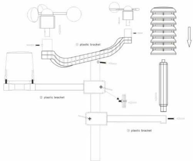
Installation
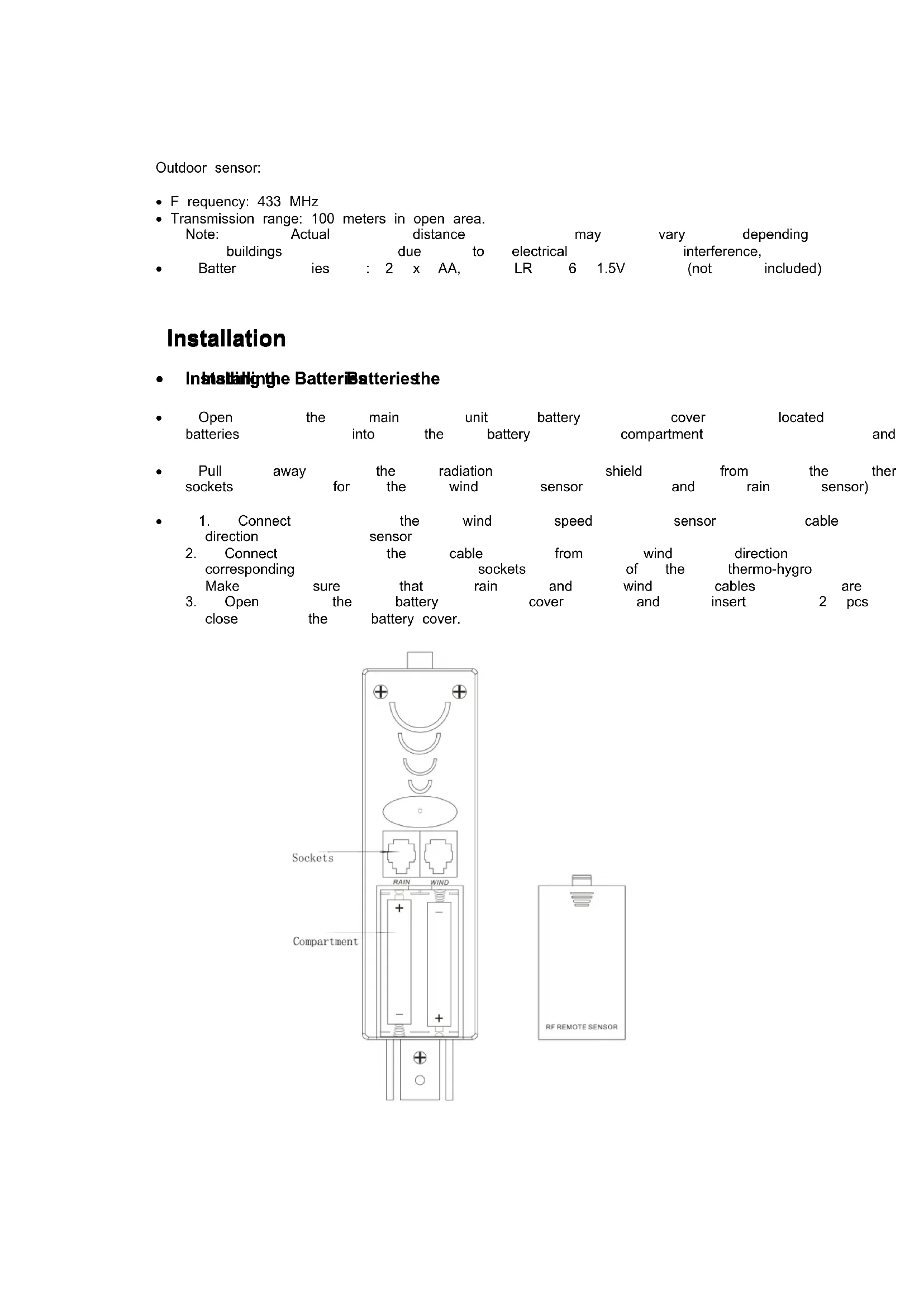
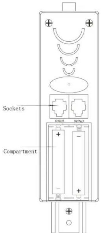
InstalbHnthe BatteriBatteriesthe
| · Open batteries | the main into the | unit battery | cover compartment | located and |
| Pull sockets | away for | the the | radiation wind | shield sensor | and | from rain | thether sensor) |
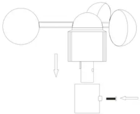
| 1. Connect direction | the sensor | wind | speed | sensor | cable | |
| 2. Connect corresponding Make | the | cable | from | wind of the | direction thermo-hygro cables | are pcs |
| sure that battery | sockets and cover | and | wind and insert | 2 | ||
| 3. Open | the | cover | ||||
NOTES:
- First insert the batteries of main unit, then insert the batteries of the outdoor sensor within 3 minutes after the main unit is powered on, to assure that the sensor data is received well.
In case of the outdoor for data more is ndhan 3 re
seconds to synchronize the sensors signal
Every time the batteries are replaced in the
Every time the batteries are replaced in 1
only if you pres the for more than 3 seconds.
Moutintthe main umitin theit
| The main unit can be placed onto side. any flat the sensors | ||||||||
| the hanging hole and from the DCF77 We strongly signal) |
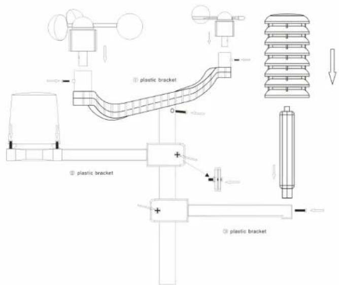
Mouttingthe outdoostosorbato the sataidtaistismast masteel
| For accurate results, the outdoor sensor | |||||||
| surface and in open area away from tree speed may be reduced causing inaccurate |
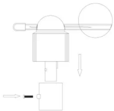
1. Mouldingthie wind speed serpaeetb the flesbplfictbracket
bracket : first check
| can rotate | freely | before | fixing. | The | wind |
| bracket provided | to allow | the | wind | to travel | |
| directions. | Please | follow | the | below | display |
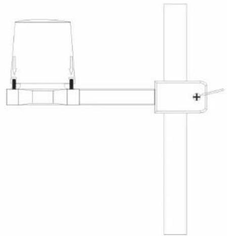
2. Mouningthe wind cirdation aeeioto the fhtspstic bphoket
bracket : first check
| fixing. | There | is |
| direction | sensor. |
| direction | sensor | before | fixing. | There | is |
| the socket | under | the | direction | sensor. |
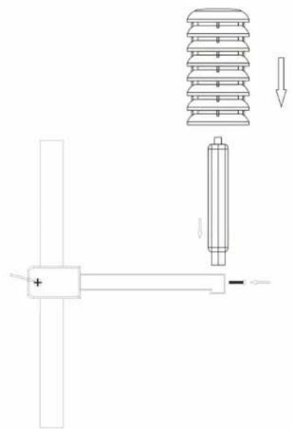
- Mounting tbeerainsssessotcdlesseecondplbckbaskt: there are vertical engraved
lines at the bottom edge of the round cover the two line into one position, then turn well, then fix them with 4 screws onto the please follow the below display :
- Mount the tbeaemohygoosensor tothieothidplastic beepfif: once
the wind sensors
and rain sensor are fixed onto the bracket, thermo-hygro sensor sensors with the p unit, then put the aspiration cover onto display:
Note
please
don
' t connect/disconnect
air for longer time in order to avoid any connection can be affected negatively!
- Mount alltheseanosscntothlaestainhessstehmasst and fix the whole sensors unit at the pre-selected outdoor area.
(Please note: make sure that all the cables lose cables to the mast)
LCD overview
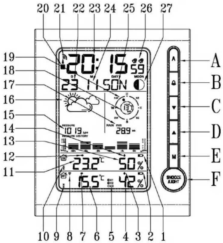
- Indoor low battery
- Outdoor low battery
- Outdoor humidity trend
- Outdoor humidity
- Function not active
- Outdoor temperature
- Outdoor temperature trend
- RF sensor symbol
- Outdoor temperature alert
- Indoor temperature alert
- Indoor temperature
- Indoor temperature trend
- Indoor humidity
- Indoor humidity trend
- Air Pressure
- Weather Forecast
- Rainfall
- Wind speed
- Wind direction
20.Summer time - RCC symbol (DCF77 time signal)
- Date
- Time
- Month
25.Day of week - Dual alarm
- Moon Phase
Initial Operation
| After The RF signal This process /humidity/wind more than 3 seconds The automatic outdoor RF reception has been completed. While the time display area. In case is not good, only blinking. Once the RCC reception is successful, no flashing, with the waves. | inserting RF signal takes about speed/wind 3 seconds receiving RCC If the reception | the batteries, symbol at speed/wind to receiving area. reception | 3 minutes. direction/rainfall. a new of the DCF77 p rocess the reception is going case is not good, only is successful, | unit will Then radio is going reception only successful, | unit and RCC |
| If, due to bad set the time manually |
Manual time set-up sttnep
In this list Up othakeettingadoosettingass12f0b0hme zone, langageslanguages, display units etc. uets
| Press and hold key “M” for 3 seconds. The 12/24 hour flashing. Use “▲” / “▼” to Press “M” to confirm. The display for the time zone is flashing. (-12 to +12). Press “M” to confirm. The DM/MD flashing, Use “▲” / “▼” to select Press “M” to confirm. The display for the year is flashing. Use “ |
| Press “M” to confirm. The display for the month is flashing. Use Press “M” to confirm. The display for the date is flashing. Use “ |
| Press “M” to confirm. The display for the hour is flashing. Use “ |
| Press “M” to confirm. The display for the minutes is flashing. Use Press “M” to confirm. The language selection for the display of the language. Press “M” to confirm The C/F for temperature flashing, Use “▲” Press “M” to confirm. The hpa/inhg for air pressure flashing, Use Press “M” to confirm. The mm/inch for rainfall and kmh/mpg flash |
Information:
- The clock automatically changes from set-up mode to time display mode if no keys are pressed for 20 seconds.
- Explanation You can manually for the time zone display: the clock to the time to the frequency the frequency the time from the time the frequency the time the frequency the time the frequency the time the frequency the time the frequency the time the frequency the time the frequency the time the frequency the time the frequency the time the frequency the time the frequency the time the frequency the time the frequency the time the frequency the time the frequency the time the frequency the time the frequency the time
Daily alarm set-alarmp set-up
| • Press | “ M” to switch | from | time | display | to | A1 | ||
| • Press | and | hold | the | key | “ M” | (MODE) | for | 3 |
| • The hour | display | of | alarm | time | is | flashing. | ||
| Press | “ M” to confirm. | |||||||
| Then | the | minutes | are | flashing. | Use | ▲ | " | |
| The same setting | as | for A2. | ||||||
Daily alarm on/off farm on/off
| 1st press | “” to activate | the alarm | 1 with |
| 2 press | “” cancel the alarm | 1, then | activate |
| 3 press | “” to activate | the alarm1 | and alarm |
| 4 press | “” cancel all the alarms |
Information:
| The clock automatically changes from set-up | |
| 20 seconds. | |
| The alarm sounds for 2 minutes if no key |
Snoopze function function
| To | activate | the | snooze | function, | follow | the |
| • | Press | SNOOZE/LIGHT | “ SNOOZE/LIGHT | “ , while | the | alarm |
| • | If the | snooze | function | is activated | the alarm | |
| • | The | alarm | repeats | after 5 minutes | . | |
| • | The | snooze | function | can be stopped | by |
12/24 hours modeours mode
| The time display can be in 12 (AM/PM) o | ||
| select | ||
fehnpepatudisplay
| The temperature display can be in °C or °F |
Press "▲" to display the indoor/outdoor “▲” for moremax./min.
than 3 seconds to clear up the max./min
mem#
Temperature alert set-up set-up alert
| • Press"A"for more than 3 seconds, the upper lit "▲ / "▼ to set the maximum alert temperature. |
| • Press AA", the lower limit of inside "to/ set ™tempatura minimum alert temperature. |
| • Press"A", the upper limit of outside temperature |
| • maximum alert temperature. |
| • Press"A", the lower limit of outside temperature |
| • minimum alert temperature. |
| • When the alert is activated, the alert symbol |
Temperature alert on/off on/off alert
| Press the keyA | “ toA | set | the | temperature | alert | on | or | off. | |
| Alert | on: | Temperature | alert | symbol | shown | ||||
| Alert | off: | Temperature | alert | symbol | goes | ||||
Information
| The set-up process cannot be completed | |
| the minimum selected temperature. | |
| The minimum temperature selected must |
5 Weathach forecast Idioms forecast
| sunny | slightly sunny | cloudy | raing | rain storm |
NOTE : The weather forecast accuracy is ap (predicted), not the current conditions. displayed during the night-time.
Barometer and blaactlaatof air parnsreskiery for tbeepasits26oy 12 hours
The local air pressure can be indicated in hP of the past 12 hours.
Wind speedindirnpknh(00286knh)
The wind speed can be shown miphpkohh (km/h), please follow the mph/kmh, the display of the speed is updated
Wind diejection
There will be 16 wind directions, the display of
Rainfall display (0~999.99mph), (0~999.99mm)
Rainfall in fathow the manual
Press "▼" to show the rainfall in 1 hour,
- Press "▼" for more than 3 seconds to c showing 1 hour, clear up the data clear in 24 hour, others clear clear up the data unchanged clear
The max. of the rainfall is up to 999.99mm limit is reached. In such a case, you have otherwise, the data can not be updated
Illumination
Press SNOOZE/LIGHT "SNOOZE/LIGHT to activate the display
Moon phase dssyase
The weather station uses preprogrammed

A BBCCDDEEFFGGH H
A: New moon B: Waxing crescent C:
D: Waxing gibbous E: Full moon F:
G: Last quarter H: Waning crescent
Comfort Zone Zone
The weather station uses a preprogrammed and shows the respective symbols.

Comfortable
dry humid
The weather station displays the low battery condition symbol to remind you to replace the
batteries
in t he
display
unit
or the
outdoor
sE
Display
unit
battery
display:
within
within
indoo
Outdoor
sensor
low
battery
display:
in
the
RF connexionetatthe ohtdoosensor to
Press
and
3
ponds key
to
search
for
the
symbol
on
display
the
OUT
area
will
reception
is more
problematic
office
buildings
(interference
Lights
etc).
The
transmission
please
put
main
unit
closer
to
window
Reception of radicabatrolled signabled
signal
The
DCF77
radio
signal
search
starts
starts
automata
During
reception,
the
tower
signal
Press
the radio
the"and two"atogtekeytedgethen "Venter (!) controlled signal
or
for
more
than
The
clock
synchroni
i
Z
es
the
DCF77
hours
at
1:00,
2:00
and
3:00
to CC
ect
potenti
unsuccessful
(
"
adio
tower
symbol
disa
pears)
4:00
and
5:00.
If
it is
not
successful,
(1)
the
rece
Information
- Flashing
Continuous
Please
computer
。
The
radio
signal
is weaker
in
rooms
with
buildings
For
extreme
cases,
ple
case:
There
are
:
atmospheric
during
night.
One
synchronization
display
accuracy at 1
second.
Tip
You can
interferences,
signal
can
be
eived,
time
manually
se
interferences,
large
received,
distance
to
the
sender,
signal
can
received,
the
clock
will
be
adjusted
Ytora
is
a
registered
trademark
of
OS
Technc
OS
Technology
AG/SA
YTORa
TPW899
CARACTERISTIQUESES É
Six bapeans, M, SIOOOZERLNGHT LIGHT
R é veil radio pilot e DCF77
R é cption du signal de l'heure automatique
m = 311
fixez
pr
é
lab
ment
que
Afflchage LOD

© OS Technology AG/SA