
FUBW50022 - Motion detector ABUS - Free user manual and instructions
Find the device manual for free FUBW50022 ABUS in PDF.
| Product type | Wireless outdoor PIR motion detector |
| Brand | ABUS |
| Model | FUBW50022 |
| Dimensions (H x W x D) | 155 x 120 x 115 mm |
| Net weight / Gross weight | 750 g / 880 g |
| Power supply | 2 lithium batteries 3 V CR123A/CR17345 (reverse polarity protection, charge indicator) |
| Radio frequency | 868.6625 MHz |
| RF output power | 10 mW (antenna input) |
| Detection range | 10, 20 or 30 m (adjustable) |
| Detection angle | 10° to 70° (adjustable with shutters) |
| Rotation / tilt | Rotation 180° / Tilt 90° |
| Protection rating | IP55 |
| Operating temperature | -20 °C to +55 °C (alkaline) / -30 °C to +60 °C (lithium) |
| Relative humidity | 75 % non-condensing |
| Security level | 2 (EN 50131-1:2006 standard) |
| Environmental class | IV (EN 50131-1:2006 standard) |
| Housing material | HDPE polyethylene, UV-resistant translucent cover |
| Main functions | Dual PIR detection, anti-tamper (cover and wall), digital white light filter, double shielding, thermal compensation, adjustable pulse count (1 or 2), test mode |
| Delivery contents | Detector, 2 lithium batteries, 2 spare clamping feet, wall adapter, drilling template, sticker (Long/Medium Beam Mask), plastic tool, 2 shutters, hex key, user manual |
| Maintenance and cleaning | Clean with a soft, dry cloth; do not use harsh chemicals; replace batteries with identical CR123A/Lithium |
| Safety | Do not expose to heat or water; do not dispose of in fire; observe battery polarity; keep out of reach of children; use only recommended batteries |
| Spare parts and repairability | CR123A batteries, clamping feet, wall adapter, shutters, stickers available from the manufacturer; repair by qualified professional |
| General information | Compliant with directive 2014/53/EU; declaration of conformity available at www.abus.com; warranty according to legal conditions; manufactured by ABUS Security-Center GmbH & Co. KG, Germany |
Frequently Asked Questions - FUBW50022 ABUS
User questions about FUBW50022 ABUS
0 question about this device. Answer the ones you know or ask your own.
Ask a new question about this device
Download the instructions for your Motion detector in PDF format for free! Find your manual FUBW50022 - ABUS and take your electronic device back in hand. On this page are published all the documents necessary for the use of your device. FUBW50022 by ABUS.
USER MANUAL FUBW50022 ABUS
Security Tech Germany
Wireless PIR outdoor motion detector
[UK] User manual....19
natural_image
Metallic 3D-rendered object with smooth curved surface and rounded edges (no text or symbols)Vorwort
natural_image
Technical illustration of a device with a pin and textured surface, labeled 'Abb. 2' (no text or symbols on the diagram itself)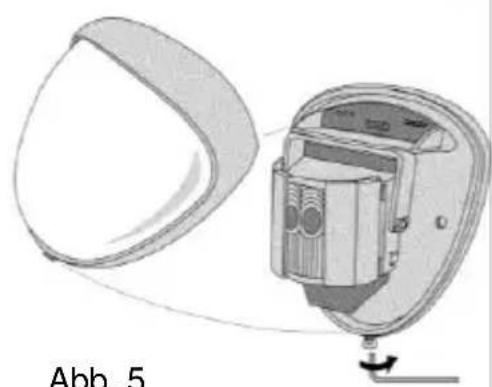
natural_image
Diagram of a device with a curved panel and internal components, labeled Abb. 5 (no text or symbols on the diagram itself)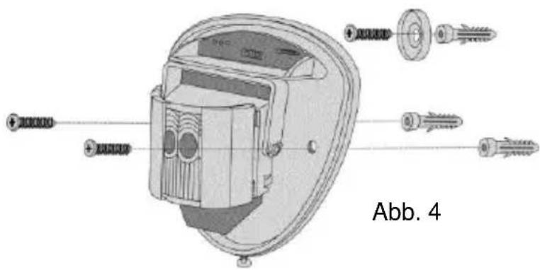
Abb. 7
natural_image
Pure diagram of vertical cylindrical objects with concentric rings, no text or symbols present
Kleintierimmunität
Höhe: 1.5m
Bereich: Maximal
Neigung: -2°
line
| x | y | |----|------| | 0 | 0 | | 5 | 0 | | 10 | 0 | | 15 | 0 | | 20 | 0 | | 25 | 0 | | 30 | 0 |natural_image
Diagram of a device interior with directional arrows indicating rotation or movement, labeled Abb. 8 (no text or symbols on the diagram itself)Programmierung
Einlernen
Wireless PIR outdoor motion detector
[UK] User manual 19
natural_image
Metallic 3D-rendered object with rounded edges and a small protrusion at the bottom (no text or symbols)Preface
Dear Customer,
Thank you for purchasing this wireless outdoor motion detector. In choosing our product, you now have a piece of equipment that is built according to state-of-the-art technology.
These instructions contain important installation and operation information. Store these instructions in a safe place for future reference. These instructions belong to this product – bear this in mind if you pass on this product to others.
Conformity
This product complies with current domestic and European regulations. Conformity has been proven. The related certifications are available from the manufacturer on request. To maintain this status and to guarantee safe operation, it is your obligation to observe these operating instructions. If you have any questions, please contact your local specialist dealer.
Hereby, ABUS Security-Center GmbH & Co. KG declares that the radio equipment type FUBW50022 is in compliance with Directive 2014/53/EU. The full text of the EU declaration of conformity is available at the following internet address: www.abus.com >> Search >> FUBW50022 >> Downloads
The Declaration of Conformity can also be obtained from the following address:
Read the notes and advice in these operating instructions carefully. If you do not follow these instructions, your guarantee claim becomes invalid. No liability can be accepted for resulting damages. No part of the product may be changed or modified in any way. Everything possible has been done to ensure that the contents of these instructions are correct. However, neither the author nor ABUS Security-Center GmbH & Co. KG can be held liable for loss or damages caused by incorrect or improper use or failure to observe the safety instructions and warnings. We reserve the right to make changes to these instructions without prior notice.
Information on the battery
The device is supplied with 3V direct current from two 3V CR123A batteries. To guarantee a long service life and avoid fire and injury, please note the following:
- Do not dispose of the batteries in domestic waste.
- The batteries must not be directly exposed to heat or sunlight, and must not be stored in a place with a very high temperature.
- The batteries must not be burned.
- The batteries must not come into contact with water.
- The batteries must not be dismantled, pierced or otherwise damaged.
-
The battery contacts must not be short-circuited.
-
The batteries must be kept away from small children.
- The batteries cannot be recharged.
Disposal
Disposal as per directive WEEE 2002/96 EC
The product contains valuable raw materials. At the end of its service life, dispose of the product according to the applicable legal requirements. Within the EU, the product and its accessories must be collected and disposed of separately. Devices displaying this symbol may not be disposed of as domestic waste. Please contact your dealer or dispose of the products at the local collection point for electronic waste.
Scope of delivery
1 x PIR wireless outdoor motion detector 1 x Allen key
2 x 3V CR123/CR17345 lithium batteries 1 x special plastic tool
1 x wall adapter for anti-removal wall contact 1 x user guide
1 x sticker (long/medium beam mask) 2 x diaphragms (sliding shutters)
1 x mounting material with drilling template
2 x spare clamping feet for anti-removal wall contact
Features
This wireless outdoor motion detector works with two independent passive infrared detectors which are fitted in a special housing for outdoor use. Both sensors have to trigger before the detector sets off an alarm. This high-precision, reliable detector is designed for using in alarm systems. The pulse counter and the detection range (from 10 to 30 metres) can be configured. It also has a lid tamper and anti-removal wall contact. In the housing, the sensor can be tilted by 180^ and rotated 90^ . This enhances outdoor surveillance performance and ensures extremely precise detection by the sensor. The PCB has an acrylic coating. The high-quality, shock-resistant housing is made of polythene and has a UV-hardened, translucent front panel which protects the sensor from rain and the effects of the environment. The combination of precision electronics, digital white light filters and double shielding prevents false alarms caused by sunlight or any other interference.
The design of the outdoor motion detector has an attractive professional look – the alignment of the sensor cannot be seen.
Installation

Do not bend or touch the antenna when installing.
natural_image
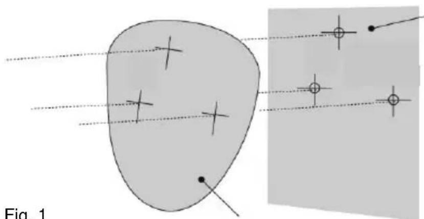
Diagram showing two abstract shapes with cross marks and connecting lines, labeled 'Fig. 1' (no text or symbols on shapes)Optional for anti-removal wall contact
Fig. 1
Template
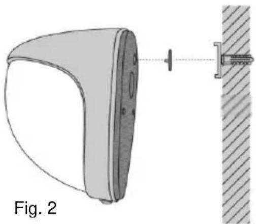
When mounting the device, make sure that moisture does not get into the housing interior as this could cause permanent damage. Use the template provided for drilling the holes for the two fixing screws and the anti-removal wall contact (if required). [See Fig. 1 and 2].
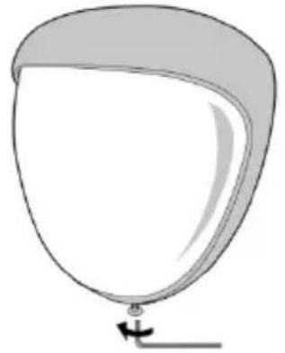
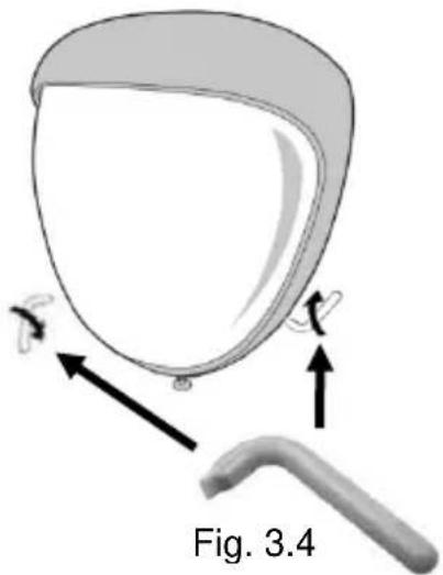
Note: For uneven walls we recommend using the adapter for the anti-removal wall contact. Remove the front cover of the sensor by unscrewing the Allen screw using the Allen key provided. [Fig. 3.1] The cover can then be swung down out of its groove and lifted off. [Abb. 3.3] If this is not possible, use the special plastic tool provided in the scope of delivery [Fig. 3.4] to loosen the cover by carefully levering sideways to the left and right without damaging it. [Fig. 3.2]
Fig. 3.1
natural_image
Simple line drawing of a balloon with a handle and arrow, no text or symbols presentFig. 3.2

natural_image
Diagram of a medical device with labeled parts and arrows, no readable text or symbols present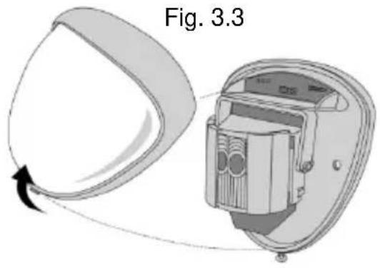
natural_image
Diagram of a device with a pin and attached bracket, labeled Fig. 2 (no text or symbols on the diagram itself)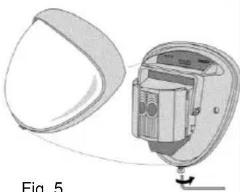
natural_image
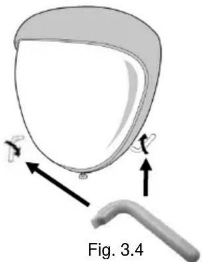
Diagram of a device with a curved panel and internal components, labeled 'Fig. 5' (no text or symbols on the diagram itself)Fig. 5

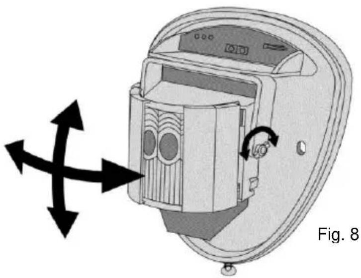
Screw the device to the wall and make sure that the anti-removal wall contact is positioned correctly and the switch is closed. [Fig. 4]. For mounting, two spare clamping feet are provided. One is 1 mm, the other one is 2 mm away from the original one. This plug connection can be removed by gently pulling the pin. [Fig. 2] When changing the electronic module, always make sure that the LED is facing forwards to ensure the sensor is aligned correctly. [See section “Aligning and masking”]
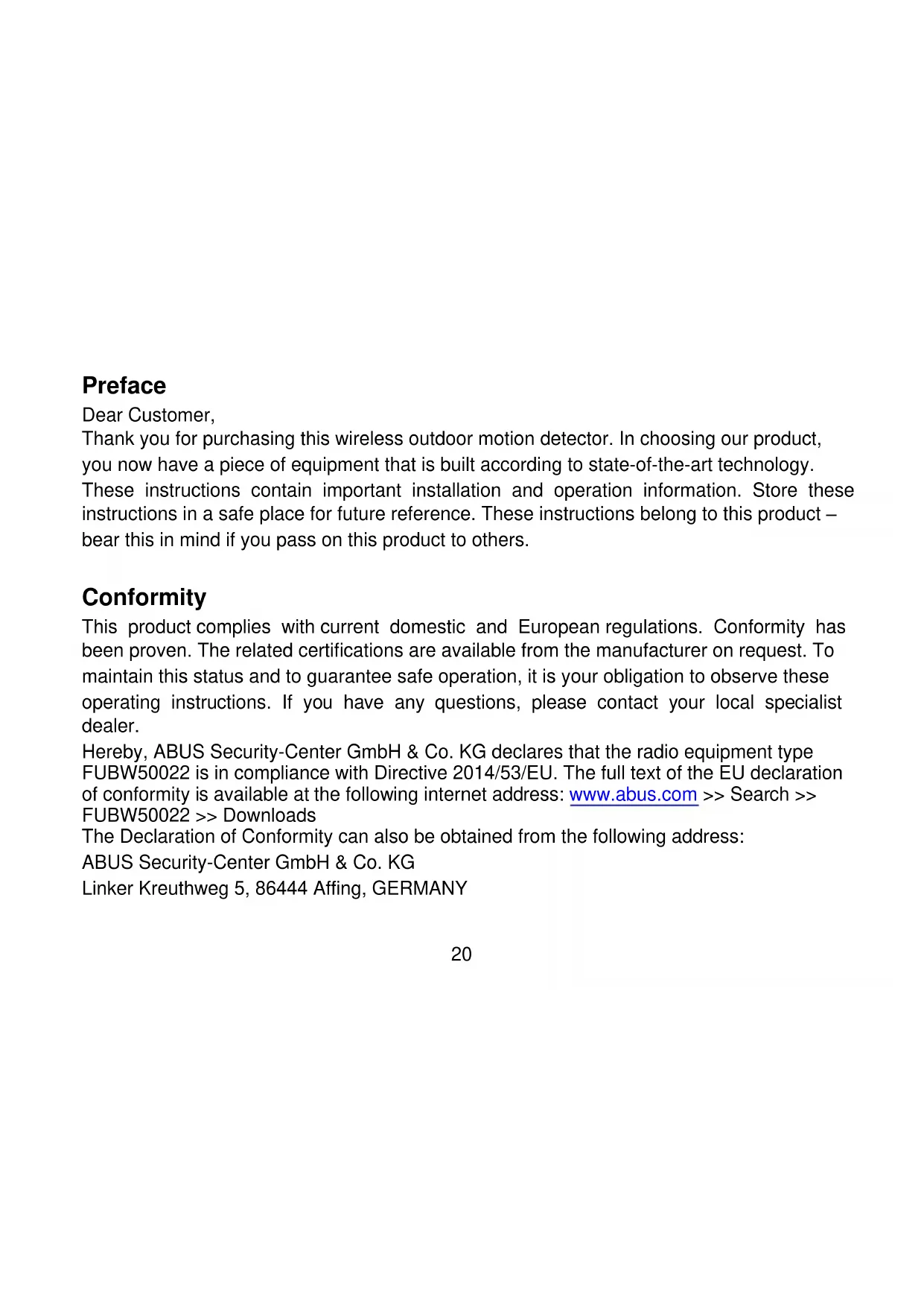
When the detector is correctly positioned and installed, replace the front cover and lock it as shown. [Fig. 5]
Walk test
The range of the detector increases without the front cover on. This is why it must be replaced for aligning the sensor correctly and for testing the outputs. Adjust the range using the following table and pan and tilt the lens module over the area to record the entire space. Press the program button to light up the red display and the pulse counter is set to 1 automatically. The device can now be aligned. The red display on the outdoor motion detector lights up with any detection. This test module is terminated automatically 5 minutes after the last detection. You can also disconnect the power supply and start the test module again.
Aligning and masking
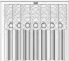
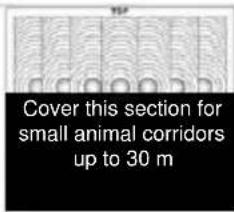
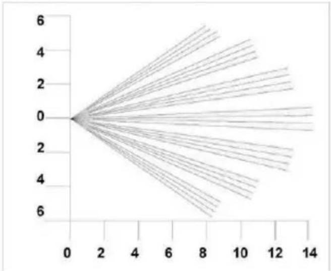
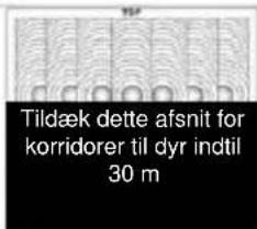
In the outdoor motion detector, the multifunctional lens produces 7 long range beams and a curtain of 7 beams at medium to short range. Movements across the beams provide the best response and the largest detection range, while movements in the direction of the detector have a weaker performance result. The device detects temperature changes and movements in the beam grid; therefore objects such as trees, bushes, ponds, heat exchange from air-conditioners and animals need to be taken into account when positioning the detector. The detector module has two sliding panels to reduce the scanning angle. Additional diaphragms are supplied to restrict the beam grid even more (for example if a minimum scanning angle of 10^ is required).
The diaphragms are attached on the panning/tilting module, as shown in Fig.7. Each section of the detector lens covers a grid area of approx. 10°. [Fig. 7]
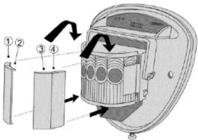
Fig. 7
If you attach the detector so that adjacent areas are also included in the surveillance area, turn the module and mask the beams horizontally or vertically which fall outside the area to be monitored. To do this use the stickers supplied (long/medium beam mask) on the flat back of the lens – see the picture on the next page. When changing the lens, always observe the correct position to keep the required detection range (marked TOP on top of the Fresnel lens) – see Fig.8.
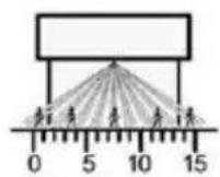
Multiple zones – optimum
Height: 3 m
Range: Maximum
tilting: 0^
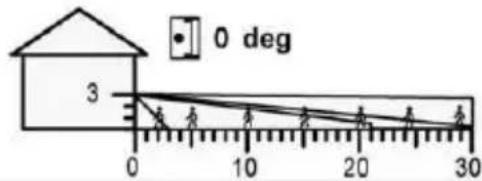
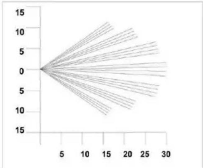
Multiple beams
Height: 6 m
Range: Maximum
tilting: 9°
natural_image
Pure diagram of vertical cylindrical elements arranged in rows, no text or symbols present
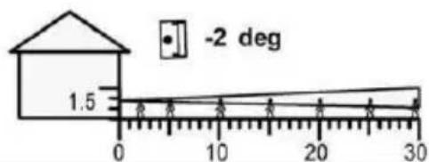
Immune to small animals
Height: 1.5 m
Range: Maximum
tilting: -2^
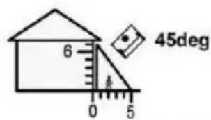
Surveillance curtain
Height: 6 m
Range: Maximum
tilting: 45°
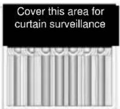
line
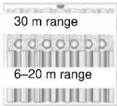
| x | y | |----|------| | 0 | 0 | | 5 | 0 | | 10 | 0 | | 15 | 0 | | 20 | 0 | | 25 | 0 | | 30 | 0 |Beam grid set to maximum range. By covering the upper section, the range is reduced to 20 m.
line
| x | y | |----|------| | 0 | 0.0 | | 2 | 1.5 | | 4 | 3.0 | | 6 | 4.5 | | 8 | 6.0 | | 10 | 7.5 | | 12 | 9.0 | | 14 | 10.5 |Beam grid set to minimum range. By covering the upper section, the range is reduced to 6 m.
natural_image
Diagram of a device interior showing internal components and directional arrows, labeled Fig. 8 (no text or symbols on the diagram itself)Programming
Teaching
To teach the wireless outdoor motion detector, set the alarm system to learning mode and press the tamper contact of the wireless outdoor detector. (Refer to the details in the user guide for the compatible component).
Note: Teaching the detector via IR LED is not possible.
Note on the perimeter warning (Secvest)
Use the “perimeter warning” as the zone type – for more details refer to the instructions for the “Secvest” alarm panel.
Configuration
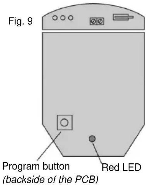
You can set several configurations on the detector – see the programming table. The default settings are shaded. Changes can be easily made. To restore the default settings, switch off the power supply to the detector; then hold down the program button [Fig. 9] and connect the power supply again (insert battery).
| Programming table | |||||
| Options | 1 | Range in m | 10 | 20 | 30 |
| 2 | Pulse counter* | 1 | 2 | ||
*PULSE COUNTER
Number of events which both sensors must detect before an output occurs.
Changing the settings
To change the settings, press the program button [Fig. 9] for the option to change – i.e. 1 x for range and 2 x for pulse counter. Wait 4 seconds until the red LED display goes out. The current setting appears on the display. To change the setting for this option, press the button until you reach the required setting. The display lights up two times and the changes are saved. (All changes made to the settings are transferred to the memory of the detector and remain there even if the power supply is interrupted.)
Example – To configure the pulse counter from the default setting "1" to "2" ...
- Press the program button two times and then release.
- Wait until the display goes out.
- The display flashes once to indicate the current setting.
- Press the program button two times to change to setting "2" and then release.
- The display flashes two times to indicate that the option has been saved and the detector returns to normal mode.
Technical data
| Power supply | 3 V DC, 2 x CR123A/CR17345(including reverse polarity protection and “empty battery” monitoring) |
| „low battery“ error message | 2,6 V nominal |
| Wireless frequency | 868.6625 MHz |
| HF transmission power | 10 mW (antenna input) |
| Detection area | 10 m, 20 m or 30 m can be selected |
| Detection angle | 10°–70° |
| Adjustment | 180° panning + 90° tiltingCovering is possible for reducing the area – if required.Alignment is not visible due to front cover with frosted glass look. |
| Fresnel lens | 28 zones per Pyro pair that can be covered with shutters or special covering tape (available in scope of delivery). |
| Absorbs 50,000 LUX white light | |
| PIR element | Double-layered silicone shielded quad element |
| Pulse counter | 1 or 2 can be selected |
| Temperature compensation | Yes (digital tuning) |
| Control | Digital microprocessor – non-volatile memory. |
| Operating temperature | - 20 °C to + 55 °C (with alkaline batteries)- 30 °C to + 60 °C (with lithium batteries) |
| Max. humidity | Average relative humidity approx. 75% – non-condensing |
| Housing | Polyethylene HDPE |
| Protection class | IP 55 |
| Dimensions (HxWxD) | 155 x 120 x 115 mm |
| Weight | 750 g net, 880 g gross. |
| Mounting height | Variable up to 6 m – optimum height at 3 m. |
| Security level | 2 (EN 50131-1: 2006) |
| Environment class | IV (EN 50131-1: 2006) – with varnish-coated electronics |
| Supervision monitoring | Yes – approx. every 4 minutes |
| Tamper monitoring | Yes (anti-removal front and wall contact) |
The manufacturer reserves the right to make technical modifications at any time.
Customer service and support
End consumer
Please consult your dealer or installer if you have any questions.
Dealer/installer
Consult our website for product information.
Wireless PIR outdoor motion detector
[UK] User manual.... 19
natural_image
Metallic curved object with a rounded top surface and small protrusions at the bottom (no text or symbols visible)Préface
Cher client, chère cliente,
natural_image
Simple line drawing of a balloon with a handle and arrow, no text or symbols presentFig. 3.2

natural_image
Diagram of a medical device with labeled parts and arrows, no readable text or symbols present

natural_image
Diagram of a device with a pin and attached bracket, labeled Fig. 2 (no text or symbols on the diagram itself)
natural_image
Diagram of a device with a curved panel and internal components, labeled Fig. 5 (no text or symbols on the diagram itself)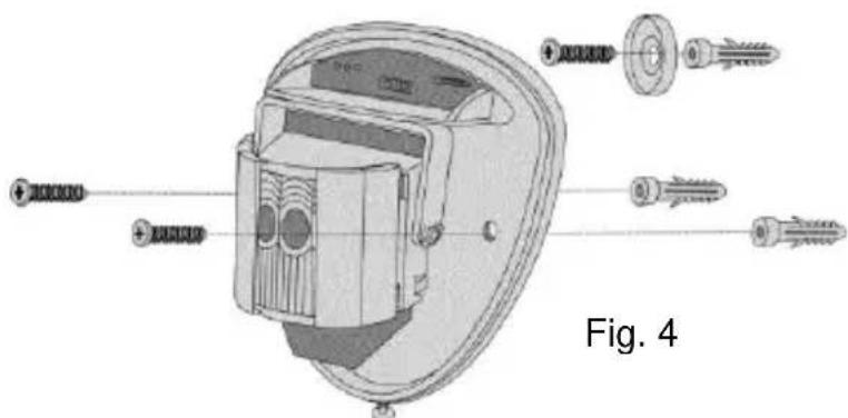
Fig. 7
natural_image
Pure diagram of vertical bars with circular cutouts, no text or symbols present
natural_image
Diagram of a device interior showing internal components and directional arrows, labeled Fig. 8 (no text or symbols on the diagram itself)Programmation
Paramétrage
Wireless PIR outdoor motion detector
[UK] User manual.... 19
[NL] Handleiding....56
natural_image
Metallic shield-shaped object with rounded edges and a small protrusion at the bottom (no text or symbols visible)Voorwoord
Geachte klant,
natural_image
Technical illustration of a device labeled 'Afb. 2' showing a curved panel and a vertical component (no text or symbols on the diagram itself)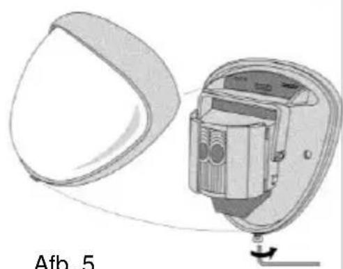
natural_image
Diagram of a device with a curved panel and internal components, labeled 'Afb. 5' (no readable text or symbols beyond label)
Afb. 7
natural_image
Pure diagram of vertical cylindrical elements arranged in rows, no text or symbols present
line
| x | y | |----|------| | 0 | 0 | | 5 | 0 | | 10 | 0 | | 15 | 0 | | 20 | 0 | | 25 | 0 | | 30 | 0 |natural_image
Diagram of a device interior with directional arrows indicating rotation or movement, labeled 'Afb. 8' (no text or symbols on the diagram itself)Programmering
Inlezen
Wireless PIR outdoor motion detector
[UK] User manual.... 19
natural_image
Metallic curved object with a rounded top surface and small protrusions at the bottom (no text or symbols visible)Forord
natural_image
Simple line drawing of a balloon with a handle and arrow, no text or symbols presentFig. 3.2
natural_image
Diagram of a medical device with labeled parts, showing a curved tool and a magnified view of the device (no text or symbols present)
natural_image
Diagram showing a device with a curved blade and internal component, labeled Fig. 3.3 (no text or symbols on the diagram itself)
natural_image
Diagram of a device with a pin and attached bracket, labeled Fig. 2 (no text or symbols on the diagram itself)
natural_image
Diagram of a device with a curved panel and internal components, labeled Fig. 5 (no text or symbols on the diagram itself)Fig. 5

Fig. 7
natural_image
Pure diagram of vertical cylindrical elements arranged in rows, no text or symbols present
Dyreimmunitet
Højde: 1,5 m
Område: Maks.
Hældning: -2°
natural_image
Diagram of a device interior showing internal components and directional arrows, labeled Fig. 8 (no text or symbols on the diagram itself)Programmering
Indkodning
Wireless PIR outdoor motion detector
[UK] User manual.... 19
natural_image
Metallic 3D-rendered object with smooth curved surface and rounded edges (no text or symbols)Prefazione
natural_image
Simple line drawing of a balloon with a handle and arrow, no text or symbols presentFig. 3.2
natural_image
Diagram of a medical device with labeled parts, showing a curved tool and a shield-like object (no text or symbols on the diagram itself)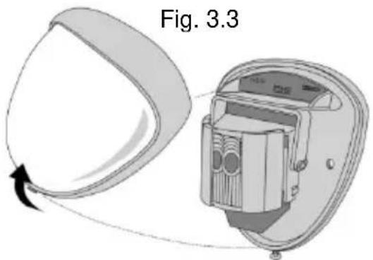

natural_image
Technical illustration of a device component with a close-up view showing a pin and textured surface (no text or symbols)
natural_image
Diagram of a device with a circular component and internal components, labeled Fig. 5 (no text or symbols on the diagram itself)Fig. 5
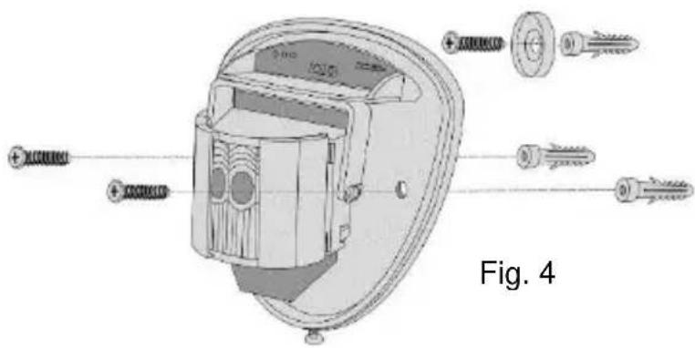
Fig. 7
natural_image
Pure diagram of vertical cylindrical objects with concentric rings, no text or symbols present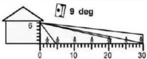
Kleintierimmunität
Höhe: 1.5m
Bereich: Maximal
line
| x | y | |----|------| | 0 | 0 | | 5 | 0 | | 10 | 0 | | 15 | 0 | | 20 | 0 | | 25 | 0 | | 30 | 0 |natural_image
Diagram of a device interior showing internal components and directional arrows, labeled Fig. 8 (no text or symbols on the diagram itself)Programmazione
Inizializzazione


- Wireless PIR outdoor motion detector
- Vorwort
- Programmierung
- Einlernen
- Preface
- Conformity
- Information on the battery
- Disposal
- Scope of delivery
- Features
- Installation
- Walk test
- Aligning and masking
- Programming
- Teaching
- Note on the perimeter warning (Secvest)
- Configuration
- Changing the settings
- Customer service and support
- End consumer
- Dealer/installer
- Préface
- Programmation
- Paramétrage
- Voorwoord
- Programmering
- Inlezen
- Forord
- Indkodning
- Prefazione
- Programmazione
- Inizializzazione
Brand : ABUS
Model : FUBW50022
Category : Motion detector