LI48631 - Basket SIEMENS - Free user manual and instructions
Find the device manual for free LI48631 SIEMENS in PDF.

User questions about LI48631 SIEMENS
0 question about this device. Answer the ones you know or ask your own.
Ask a new question about this device
Download the instructions for your Basket in PDF format for free! Find your manual LI48631 - SIEMENS and take your electronic device back in hand. On this page are published all the documents necessary for the use of your device. LI48631 by SIEMENS.
USER MANUAL LI48631 SIEMENS
Operating and installation instructions
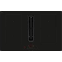
natural_image
Technical line drawing of a cabinet with open door, side shelf, and cylindrical component (no text or symbols)de Seite 3-18
en page 19 – 34
fr page 35 - 50
nl pagina 51 – 66
it pagina 67 - 82
es página 83 - 98
pt página 99 – 114
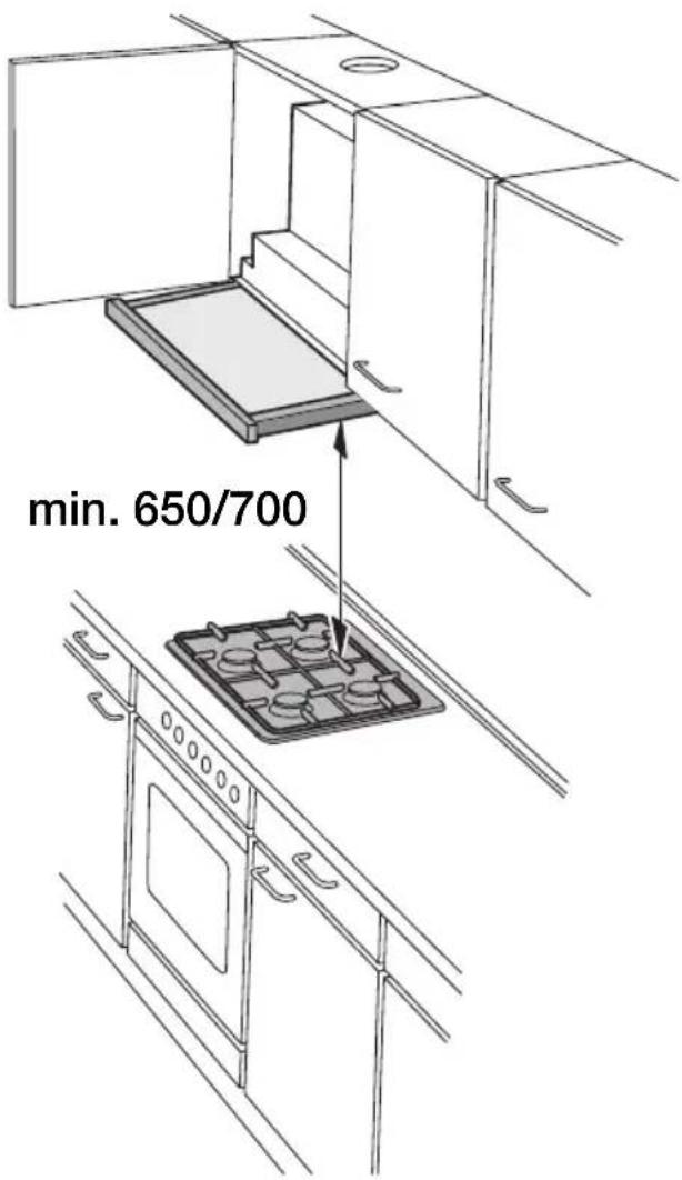
Abb. 1
GAS ELEKTRO
GAZ ELECTR.
KAASU ELETT.
GASS EL.
text_image
min. 650/700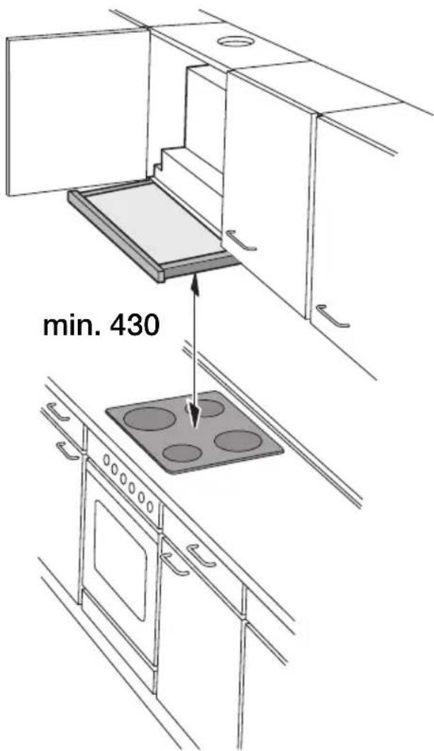
text_image
min. 430natural_image
Technical line drawing of a cabinet interior with open door, side shelf, and cylindrical component (no text or symbols)text_image
Hand-drawn interface with icons for zoom, refresh, and navigation controlsLüfterstufen:
text_image
Diagram of a control panel with icons and a hand gesture pointing to the left paneltext_image
Control panel with indicator lights, buttons, and function buttons labeled with icons and numbersnatural_image
Technical diagram of a mechanical ventilation system with arrows indicating airflow or movement (no text or symbols present)natural_image
Technical diagram of a mechanical device with arrows indicating airflow or movement (no text or symbols)natural_image
Diagram of a computer ventilation system showing airflow path and component placement (no text or labels)natural_image
Illustration of a magnifying glass with a handle and circular lens (no text or symbols)natural_image
Illustration of a hand holding a cable with a magnified circular component above it, no text or symbols present.text_image
Technical diagram showing a mechanical assembly with labeled components and a screw, including a screwdriver and a button.natural_image
Diagram of a server rack with an inset magnified view showing internal components (no text or symbols)natural_image
Three schematic diagrams showing airflow patterns between structural elements, with no visible text or symbols.natural_image
Diagram of a mechanical or fluidic system with directional arrows indicating flow or movement, no text or symbols present.natural_image
Diagram of a mechanical or electrical enclosure with directional arrows indicating movement or force, no text or symbols present.natural_image
Diagram of a screwdriver inserted into a mechanical component, showing a black arrow indicating the insertion direction (no text or symbols present)natural_image
Diagram of a screwdriver inserted into a mechanical component, showing tool path and mounting detail (no text or symbols)Gewicht in kg:
natural_image
Technical illustration of a mechanical assembly with screw and housing components (no text or symbols)natural_image
Mechanical assembly diagram showing a screwdriver inserted into a component (no text or symbols visible)text_image
Weather icon buttons including sun, moon, and alarm symbol with numeric values for weather indication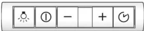
text_image
Control panel with lightbulb icon, radio button, minus sign, plus and down iconsOperating instructions:
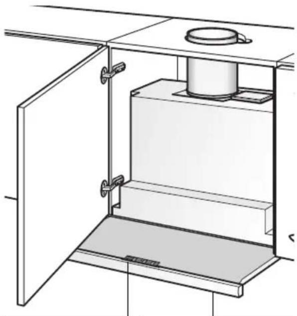
Description of appliance
natural_image
Technical line drawing of a cabinet interior with open door, side shelf, and cylindrical component (no text or symbols)Light / fan switches Filter drawer
Operating modes
Exhaust-air mode:
☐ The extractor-hood fan extracts the kitchen vapours and conveys them through the grease filter into the atmosphere.
☐ The grease filter absorbs the solid particles in the kitchen vapours.
☐ The kitchen is kept almost free of grease and odours.
If the extractor hood is operated in exhaust-air mode at the same time as a flue-type heater (e.g. gas, oil or solid-fuel heater, instantaneous water heater, boiler), ensure that there is an adequate air supply which the heater requires for combustion.
Safe operation is possible provided that the partial vacuum in the room in which the heater is installed does not exceed 4 Pa (0.04 mbar).
Operating modes
This can be achieved if the combustion air is able to flow through non-lockable openings, e.g. in doors, windows and in conjunction with an air supply/air-intake wall box or by other technical procedures such as reciprocal interlocking.
If the air intake is inadequate, there is a risk of poisoning from combustion gases which are drawn back into the room.
An air-intake/exhaust-air wall box by itself is no guarantee that the limiting value will not be exceeded.
Note: When assessing the overall requirement, the combined ventilation system for the entire household must be taken into consideration. This rule does not apply to the use of cooking appliances, such as hobs and ovens.
Unrestricted operation is possible if the extractor hood is used in recirculating mode – with activated carbon filter.
Circulating-air mode:
☐ An activated carbon filter must be fitted for this operating mode (see Filters and maintenance).
⚠ The complete installation set and replacement filters can be obtained from specialist outlets.
The corresponding accessory numbers can be found at the end of these operating instructions.
☐ The extractor-hood fan extracts the kitchen vapours which are purified in the grease filter and activated carbon filter and then conveyed back into the kitchen.
☐ The grease filter absorbs the grease particles in the kitchen vapours.
☐ The activated carbon filter binds the odorous substances.
⚠️ If no activated carbon filter is installed, it is not possible to bind the odorous substances in the cooking vapours.
Before using for the first time
Important notes:
☐ The Instructions for Use apply to several versions of this appliance. Accordingly, you may find descriptions of individual features that do not apply to your specific appliance.
☐ This extractor hood complies with all relevant safety regulations.
Repairs should be carried out by qualified technicians only.
Improper repairs may put the user at considerable risk.
Before using your appliance for the first time, please read these Instructions for Use carefully. They contain important information concerning your personal safety as well as on use and care of the appliance.
☐ Please retain the operating and installation instructions for a subsequent owner.
⚠️ Do not use the appliance if damaged.
⚠ The appliance is not intended for use by young children or infirmed persons without supervision.
Young children should be supervised to ensure they do not play with the appliance.
⚠️ If the connecting cable for this appliance is damaged, the cable must be replaced by the manufacturer or his customer service or a similarly qualified person in order to prevent serious injury to the user.
⚠ The appliance may be connected to the mains by a qualified technician only.
⚠ Dispose of packaging materials properly (see Installation instructions).
⚠ This extractor hood is designed for domestic use only.
Light bulbs must always be fitted when the extractor hood is in use.
⚠️ Defective bulbs should be replaced immediately to prevent the remaining bulbs from overloading.
⚠️ Never operate the extractor hood without a grease filter.
⚠️ Overheated fat or oil can easily catch fire.
If you are cooking with fat or oil, e.g. chips, etc., never leave the cooker unattended.
⚠️ Never allow children to play with the appliance.
Do not let adults or children operate the appliance unsupervised:
- if they are mentally or physically unable to use the appliance safely and correctly,
- if they don't have the knowledge and experience to use the appliance safely and correctly.
⚠️Do not flambé food directly under the extractor hood.
! Risk of grease filter catching fire due to flames.
⚠️ The hotplates must always be covered with a utensil.
⚠️ Restrictions apply to the use of the extractor hood over a solid-fuel burner (coal, wood, etc.). (See Installation instructions).
Gas hobs / Gas cookers
Do not use all the gas hotplates simultaneously for a prolonged period (max. 15 minutes) at maximum thermal load, otherwise there is a risk of burns if the housing surfaces are touched or a risk of damage to the extractor hood. If the extractor hood is situated over a gas hob, operate the hood at maximum setting if three or more gas hotplates are operated simultaneously.
Operating the extractor hood
⚠ The most effective method of removing vapours produced during cooking is to:
☐ Switch the ventilator ON
as soon as you begin cooking.
☐ Switch the ventilator OFF
a few minutes after you have finished cooking.
☐ The fans in this appliance can be switched to the desired setting by hand (manual mode) or can be controlled fully automatically with the automatic function according to your requirements (automatic mode).
Switching on manual mode:
Press the Ⓐ or + button.
☐ The fan starts at Setting ☑.
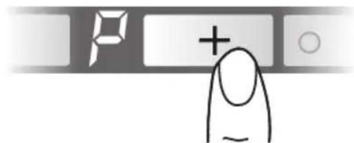
Switching on the fan settings/intensive setting:
- To increase the fan settings or switch on the intensive setting P, press the + button.
☐ The intensive setting operates at maximum power which should be used only briefly. If the intensive setting is not switched off manually, the fan automatically switches back to Setting ^2 after 10 minutes. - To switch off the intensive setting P or switch back to fan settings 3 - 2 - and switch off the extractor hood completely, press the - button.
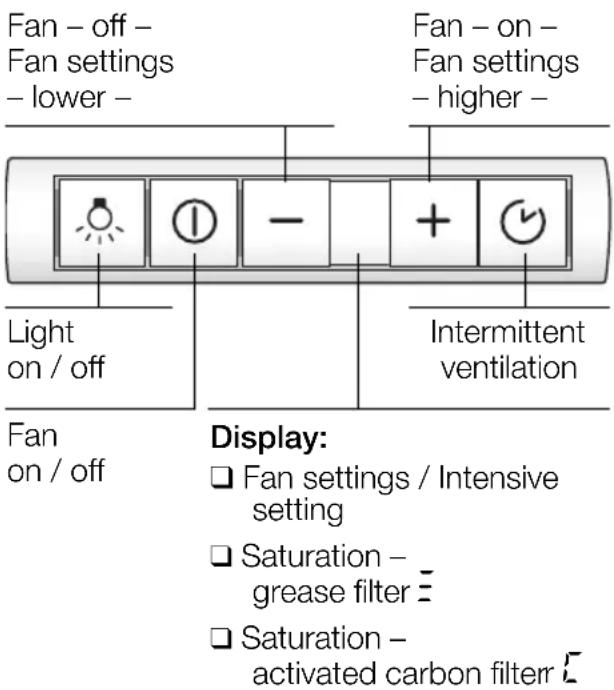
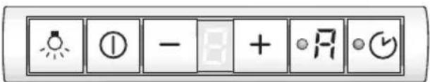
Appliances without automatic mode: Appliances with automatic mode:
text_image
Fan - off - Fan settings - lower - Light on / off Fan on / off Display: □ Fan settings / Intensive setting □ Saturation - grease filter = □ Saturation - activated carbon filter £ Fan - on - Fan settings - higher - Intermittent ventilation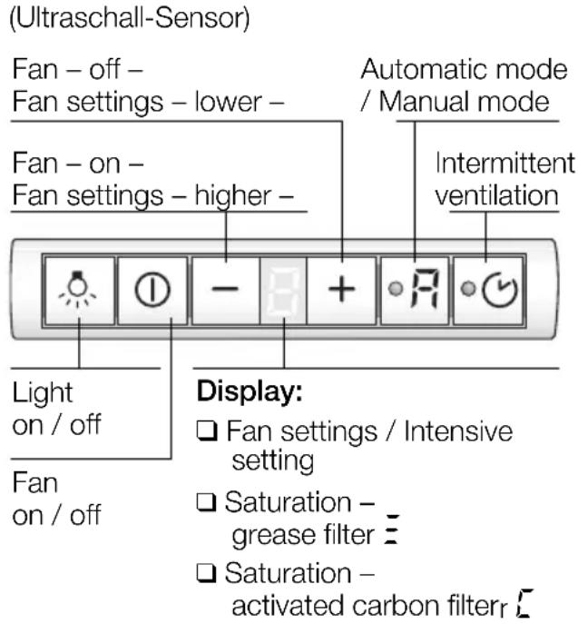
text_image
(Ultraschall-Sensor) Fan - off - Fan settings - lower - Fan - on - Fan settings - higher - Automatic mode / Manual mode Intermittent ventilation Light on / off Fan on / off Display: □ Fan settings / Intensive setting □ Saturation - grease filter ≡ □ Saturation - activated carbon filterSwitching over to automatic mode:
☐ To switch from manual mode to automatic mode at any time, press the 🔒 button.
Operating the extractor hood
Switching on automatic mode:
Press the A button.
☐ The fan runs at least at Setting 1.
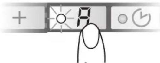
text_image
Hand-drawn interface with icons for addition, summing, rotation, and navigation controlsFan settings:
☐ If required, the optimum fan setting is actuated automatically via a sensor.
☐ The automatic function operates at Settings 1 - 3.
Intensive setting:
- To switch on the intensive setting P, press the + button.
text_image
P +☐ Automatic mode has been switched off.
☐ The intensive setting operates at maximum power which should be used only briefly.
If the intensive setting is not switched off manually, the fan automatically switches back to the optimum fan setting after 10 minutes.
- To switch off the intensive setting, press the - button.
☐ Automatic mode has been switched on again.
Switching over to manual mode:
☐ To switch from automatic mode to manual mode at any time, press the R button.
Intermittent ventilation
☐ Used for ventilating the kitchen at hourly intervals at the lowest fan setting, round the clock.
Switching on appliance:
Press the ○ 🎨 button and insert the filter drawer.

text_image
+ - A ≈☐ The fan runs for 5 minutes at Setting 1, then switches off for 55 minutes. This process is repeated every hour.
Switching off:
Press the ○ 📋 button.
Operating the extractor hood
Switching off:
There are 2 different methods of switching off the appliance whether in manual or automatic mode.
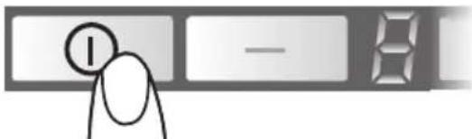
Switching off directly:
Press the Ⓐ button.
text_image
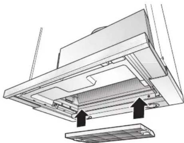
I — 8Important: All fan functions are switched off.
Switching off appliance with fan run-on:
Insert filter drawer all the way. The fans operate in the last switched-on stage for around another 10 minutes and then switch off.
☐ When the extractor hood is switched off, the operating mode and the fan setting are saved. When the filter drawer is pulled out, the extractor hood switches on again at the saved settings.
☐ If the intensive setting is switched on when the filter drawer is inserted, the intensive setting automatically switches back during run-on.
☐ If intermittent ventilation is switched on, it continues operating normally following run-on.
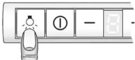
Light
☐ The light can be used at any time, even when the appliance has been switched off.
Switching on/off: Press the 🔊 button.
text_image
Diagram showing a finger pressing a button with icons and numbers, likely indicating a status or function in a control panel.Adjusting the brightness:
☐ Hold down the ⚙ button until the desired brightness is obtained.
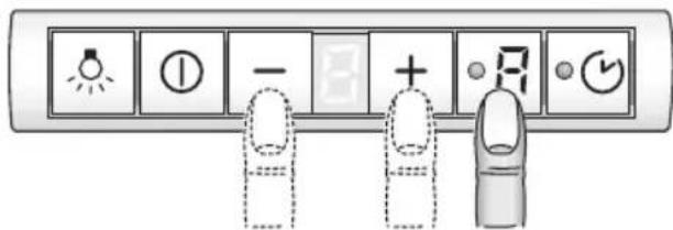
Adjusting the sensitivity of the sensor control:
-
Press and hold down the automatic button.
-
To display the current sensitivity, press the + or - button.
-
You can now change the sensitivity of the sensor control by pressing the + or - button.
text_image
Control panel with indicator lights, buttons, and three finger icons for display or operation□ Factory setting: 7.
☐ Lowest setting: ☐.
☐ Highest setting: 9.
Filters and maintenance
Grease filters:
Metal-mesh filters are used to trap the grease particles in the cooking vapours.
The filter mats are made from non-combustible metal.
Caution:
As the filter becomes more and more saturated with grease, there is an increased risk of fire and the function of the extractor hood may be impaired.
Important:
By cleaning the metal grease filters at appropriate intervals, the possibility of them catching fire as a result of a build-up of heat such as occurs when deep-fat frying or roasting is taking place, is reduced.
Saturation indicator:
When the grease filters reach saturation point, an acoustic signal is sounded for 6 seconds after the fan has switched off, and an ≡ appears in the display. The grease filters should be cleaned straight away.
Cleaning the metal-mesh grease filters:
☐ The filters can be cleaned in a dishwasher. However, they may become slightly discoloured.
Important:
Do not wash highly saturated metal-mesh grease filters with other utensils.
☐ If cleaning the filters by hand, soak them in a hot soap solution. Then brush the filters, rinse thoroughly and leave to drain.
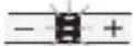
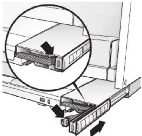
Removing and inserting the metal-mesh grease filters:
Warning: The halogen bulbs must be switched off and cool.
- Pull the filter drawer all the way out.
- Depress both catches at the front of the grease filter and remove the grease filter.
natural_image
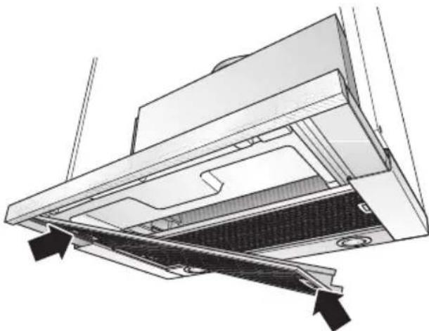
Technical diagram of a mechanical ventilation system with arrows indicating airflow or movement (no text or symbols present)- Depress the catches at the rear of the grease filter and remove the grease filter.
natural_image
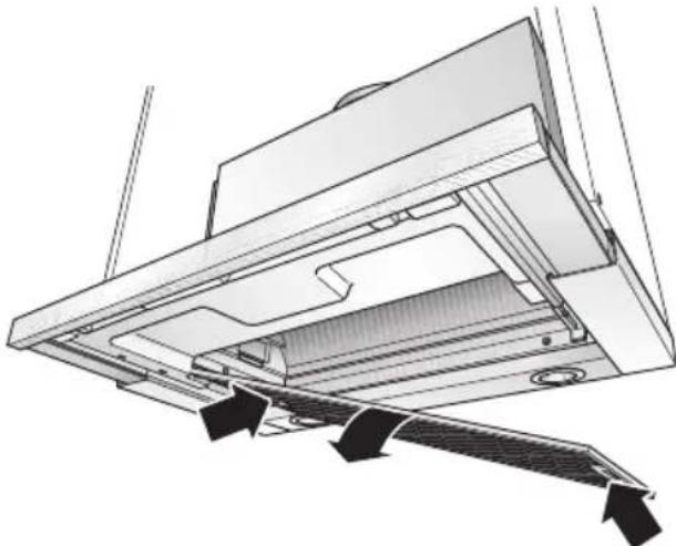
Technical diagram of a mechanical device with internal components and directional arrows indicating flow or movement (no text or symbols)- Clean the filters.
-
Insert the clean filters back into the hood.
-
Cancel the = display. ☐ Press the Ⓐ button for at least 3 seconds. The = display then goes out.
Filters and maintenance
Activated carbon filter:
For neutralizing odours in recirculating mode.
Caution:
As the filter becomes more and more saturated with grease, there is an increased risk of fire and the function of the extractor hood may be impaired.
Important:
Change the activated carbon filter promptly to prevent the risk of fire from the accumulation of heat when deep-fat frying or roasting.
Inserting the filter:
Warning: The halogen bulbs must be switched off and cool.
-
Remove the metal filters (see "Removing and inserting the metal grease filters").
-
Insert the activated carbon filter.
natural_image
Diagram of a computer ventilation system showing airflow direction and component placement (no text or labels)-
Engage the catches at both sides.
-
Insert the metal-mesh grease filters (see "Removing and inserting the metal-mesh grease filters").
-
Cancel the □ display.
☐ Press the Ⓑ button for at least 3 seconds. The ℓ display then goes out.
Saturation indicator:
When the activated carbon filter is saturated, an acoustic signal is emitted for 6 seconds when the fan has switched off and is displayed. The activated carbon filter should then be replaced immediately.
Removing the filter:
Warning: The halogen bulbs must be switched off and cool.
-
Remove the metal-mesh filters.
-
Depress the catches on both sides of the filter and remove the activated carbon filter.
-
Replacing the activated carbon filter:
☐ A replacement filter can be obtained from any authorized dealer (see optional accessories).
☐ Use original filters only. This will ensure maximum performance.
- Insert the grease filters.
Disposing of the old activated carbon filter:
□ Activated carbon filters do not contain any pollutants and can be disposed of with domestic refuse.
Cleaning and care
Isolate the extractor hood by pulling out the mains plug or switching off the fuse.
Do not clean the extractor hood with abrasive sponges or with cleaning agents which contain sand, soda, acid or chlorine!
☐ Clean the extractor hood with a hot soap solution or a mild window cleaner.
☐ Do not scrape off dried-on dirt but wipe off with a damp cloth.
☐ When cleaning the grease filters, remove grease deposits from accessible parts of the housing. This prevents the risk of fire and ensures that the extractor hood continues operating at maximum efficiency.
⚠ Clean the operating buttons with a mild soapy solution and a soft, damp cloth only. Do not use stainless-steel cleaner to clean the operating buttons.
Stainless steel surfaces:
☐ Use a mild non-abrasive stainless steel cleaner.
☐ Clean the surface in the same direction as it has been ground and polished.
☐ We recommend our stainless steel cleaner no. 461731. See enclosed service booklet for order address.
Aluminium, coated and plastic surfaces:
☐ Do not use dry cloths.
☐ Use a mild window cleaning agent.
☐ Do not use aggressive, acidic or caustic cleaners.
Observe the warranty regulations in the enclosed service booklet.
Replacing the light bulbs
- Switch off the extractor hood and pull out the mains plug or switch off the electricity supply at the fuse box.
When switched on, the halogen bulbs become very hot. Even for some time after the bulbs have been switched off there is still a risk of burns.
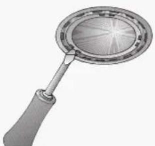
- Remove the bulb ring with a screwdriver or similar tool.
natural_image
Illustration of a magnifying glass with a circular lens and handle (no text or symbols)- Replace the halogen light bulb (conventional halogen bulb, 12 Volt, max. 20 Watt, G4 cap). Caution: Refer for plug-in lampholder. Take hold of the bulb with a clean cloth.
natural_image
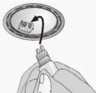
Illustration of a hand holding a tool interacting with a circular device (no text or symbols visible)-
Re-insert the bulb ring.
-
Plug the appliance into the mains or switch it on at the fuse box.
Note: If the light does not function, check that the bulbs have been inserted correctly.
Moving the operating unit
You can move the operating unit from the middle of the filter drawer to the left or right side.
The operating unit can also be fitted at the front in a handle moulding available as an optional accessory or in the enclosed handle moulding (see optional accessories on back page).
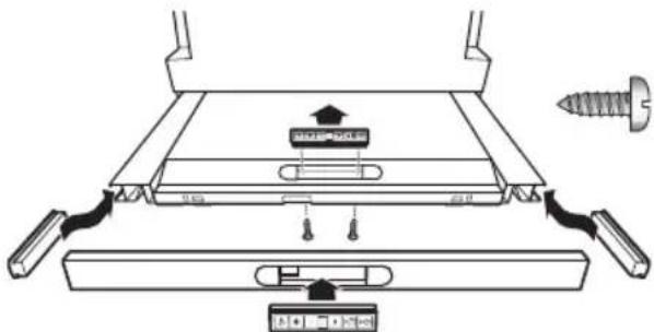
text_image
Technical diagram showing a mechanical assembly with labeled components and a screw, likely illustrating a gear or mounting mechanism.- Loosen the 2 screws from below.
- Remove the operating unit and disconnect the plug from the ribbon cable.
- Remove the side cover from the filter drawer.
- Connect the plug of the side ribbon cable to the operating unit.
- Insert the operating unit into the side of the filter drawer.
⚠️ Insert the excess ribbon cable.
natural_image
Diagram of a server rack with an inset magnified view showing internal components (no text or symbols)- Insert the cover into the middle of the filter drawer and screw on the cover from below with 2 screws.
Setting the saturation indicator
If the operating mode is to be switched over (exhaust air/circulating air mode), the saturation indicator for the filters must also be switched over (see Installation instructions).
Faults
If or is displayed:
☐ See "Filters and maintenance" Section.
If the extractor hood cannot be operated:
☐ Isolate the extractor hood for approx. 1 minute by pulling out the mains plug or switching off the fuse. Then switch on again..
If you have any questions or if a fault occurs, please call Customer Service.
(See list of Customer Service representatives).
When you call, please quote the following:
E-Nr.
FD
Enter the numbers in the above box. The numbers can be found on the rating plate inside the extractor hood following removal of the grease filters.
The manufacturer of the extractor hoods accepts no liability for complaints which can be attributed to the design and layout of the pipework.
Important information
⚠️Old appliances are not worthless rubbish. Valuable raw materials can be reclaimed by recycling old appliances. Before disposing of your old appliance, render it unusable.
⚠️You received your new appliance in a protective shipping carton. All packaging materials are environmentally friendly and recyclable. Please contribute to a better environment by disposing of packaging materials in an environmentally-friendly manner.
Please ask your dealer or inquire at your local authority about current means of disposal.
⚠ The extractor hood can be used in exhaust air or circulating air mode.
⚠ Always mount the extractor hood over the centre of the hob.
△Minimum distance between electric hob and bottom edge of extractor hood: 430 mm, Fig. 1.
The extractor hood must not be installed over a solid fuel cooker – a potential fire hazard (e.g. flying sparks) – unless the cooker features a closed, non-removable cover and all national regulations are observed.
⚠ The smaller the gap between the extractor hood and hotplates, the greater the likelihood that droplets will form on the underside of the extractor hood.
Additional information concerning gas cookers:
When installing gas hotplates, comply with the relevant national statutory regulations (e.g. in Germany: Technische Regeln Gasinstallation TRGI).
⚠ Always comply with the currently valid regulations and installation instructions supplied by the gas appliance manufacturer.
⚠️Only one side of the extractor hood may be installed next to a high-sided unit or high wall. Gap at least 300 mm.
⚠ Minimum distance on gas hotplates between the upper edge of the trivet and lower edge of the extractor hood: 650 mm, Fig. 1.
With automatic
cooker hoods:
700 mm, Fig. 1.
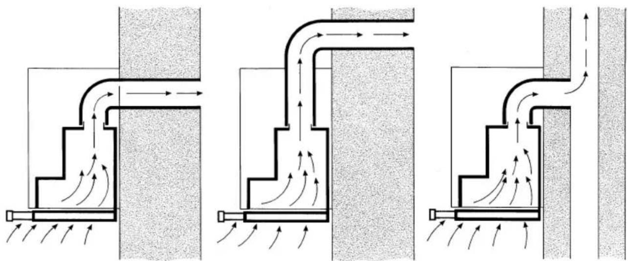
Exhaust-air mode
natural_image
Three schematic diagrams showing airflow patterns between structural elements, with no visible text or symbols.The exhaust air is discharged upwards through a ventilation shaft or directly through the outside wall into the open.
Exhaust air must not be discharged via a smoke or exhaust gas flue which is already in use or via a shaft which is used for ventilating rooms in which fireplaces are located.
Discharge exhaust air in accordance with official and statutory regulations (e.g. national building regulations).
Discharge of air into smoke or exhaust air flues which are not in use requires the consent of a heating engineer.
If the extractor hood is operated in exhaust-air mode at the same time as a flue-type heater (e.g. gas, oil or solid-fuel heater, instantaneous water heater, boiler), ensure that there is an adequate air supply which the heater requires for combustion.
Safe operation is possible provided that the partial vacuum in the room in which the heater is installed does not exceed 4 Pa (0.04 mbar).
This can be achieved if the combustion air is able to flow through non-lockable openings, e.g. in doors, windows and in conjunction with an air supply/air-intake wall box or by other technical procedures such as reciprocal interlocking.
If the air intake is inadequate, there is a risk of poisoning from combustion gases which are drawn back into the room.
An air-intake/exhaust-air wall box by itself is no guarantee that the limiting value will not be exceeded.
Note: When assessing the overall requirement, the combined ventilation system for the entire household must be taken into consideration. This rule does not apply to the use of cooking appliances, such as hobs and gas cookers.
The extractor hood can be used without restriction in circulating air mode – with an activated carbon filter.
For exhaust air mode a one-way flap should be installed in the extractor hood unless already installed in the exhaust air pipe or wall box.
If a one-way flap is not enclosed with the extractor hood, you purchase one from your dealer.
If the exhaust air is conveyed through the outside wall, a telescopic wall box should be used.
Optimum efficiency of the extractor hood:
☐ Short, smooth exhaust pipe.
☐ As few bends as possible.
☐ Pipe diameter as large as possible (ideally 150 mm dia.) and wide pipe bends.
If long, rough exhaust-air pipes, many pipe bends or smaller pipe diameters are used, the air extraction rate will no longer be at an optimum level and there will be an increase in noise.
The manufacturer of the extractor hoods accepts no liability for complaints which can be attributed to the design and layout of the pipework.
Round pipes Short exhaust air pipe: inside diameter min. 120 mm, Longer exhaust air pipe: inside diameter min. 150 mm.
☐ Flat ducts must have an inside cross-section equivalent to that of the round pipes.
There should be no sharp bends.
120 mm dia. approx. 113 cm ^2 150 mm dia. approx. 177 cm ^2
☐ If pipe diameters differ, insert sealing strip.
☐ Ensure that there is an adequate air supply for exhaust air mode.
Exhaust air directed backwards:
Only possible inside tall wall cupboards depending on the size of the exhaust air pipe.
☐ Make a hole in the rear panel of the wall cupboard, cutting out a notch for the power supply cable.
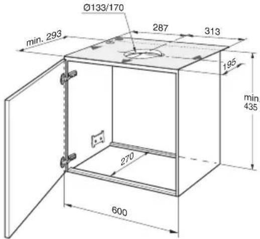
Exhaust air directed upwards:
text_image
Ø133/170 287 313 min. 293 195 min. 435 270 600- Make a hole in the top of the wall cupboard, cutting out a notch for the power supply cable.
-
template I enclosed -.
-
If fitted, cut out the cupboard base to a min. depth of 270 mm over the entire width.
Connecting a 150 mm exhaust pipe:
☐ Attach the exhaust pipe directly to the air connector.
Connection of 120 mm ∅ exhaust air pipe:
☐ Attach enclosed reducing connector to the air outlet.
Holes in the air outlet must be sealed.
☐ Attach exhaust air pipe to the reducing connector.
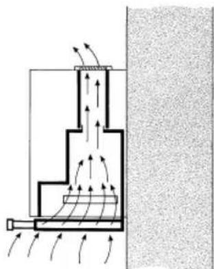
Circulating-air mode
☐ With activated carbon filter if exhaust-air mode is not possible.
⚠ The complete installation set can be obtained from specialist outlets.
The corresponding accessory numbers can be found at the end of these operating instructions.
natural_image
Diagram of a mechanical or fluidic system with directional arrows indicating flow or movement, no text or symbols present.Preparing the wall cupboard
This extractor hood is designed to be installed in a wall cupboard with the following dimensions:
width: 600 mm
depth: 293 to 350 mm
height: min. 435 mm.
If the cupboard is deeper than 293 mm, the extractor hood can be moved back, e.g. to put a spice rack in front of the extractor hood.
To do this, place the template ⑪ further back.
⚠ Ensure that the cupboard is stable both during and after installation, even if fitted at the end of a row of kitchen units.
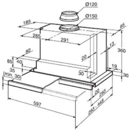
text_image
Ø120 Ø150 185 265 291 85 80 20 360 13 85 40 30 19 30 35 (min. 30) 20 230 448 597- Mark two attachment points on both the right and left inside faces of the cupboard and make holes with a bradawl.
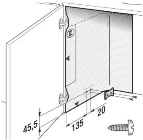
text_image
45,5 135 20When you drill:
2 mm diameter – max. 10 mm in depth.
Use the enclosed template Ⓗ to mark the attachment points.
-
Screw on both attachment plates.
-
Attach the door to the cupboard and align.
⚠️ Observe the minimum distance between hotplates and extractor hood! Fig. 1.
Switching over from exhaust air to circulating air mode
Switching the electronic control system to circulating air mode:
☐ The extractor hood has been set to exhaust air mode at the factory.
Before the mode can be changed, the extractor hood must have been connected and should be switched off.
text_image
Control panel icons with symbols for light, minus sign, plus, and function buttons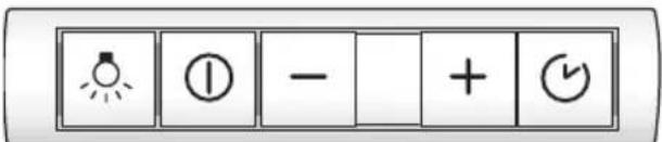
text_image
Control panel with lightbulb icon, radio button, minus sign, plus and down icons- Press and hold down the Ⓐ button.
- Press the 📄 button for approx. 3 seconds.
□ A □ is displayed.
- Release the buttons.
☐ The display goes out shortly afterwards.
Resetting to exhaust-air mode:
- Repeat the procedure.
□ A ≡ is displayed. - Release the buttons.
☐ The display goes out shortly afterwards.
Fitting into wall cupboard
⚠️ Check door alignment and readjust if necessary.
- Remove grease filter (see Operating instructions).
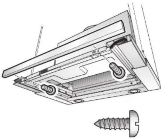
- Lift the extractor hood into the cupboard from below until both fixing lugs have locked firmly into position.
natural_image
Diagram of a laboratory apparatus with arrows indicating flow or movement, no text or symbols present- Tighten the two fixing screws with a screwdriver (cordless).
natural_image
Diagram of a screwdriver inserted into a mechanical device component, showing a black arrow indicating the insertion direction (no text or symbols present)☐ Align the extractor hood in the cupboard.
☐ Carefully tighten both fastening screws.
⚠️ Check that the extractor hood is secure in the cupboard.
- If required, shorten the wall cover to the required dimension (e.g. saw off). Attach the wall cover with the enclosed clips. Screw the wall cover to the wall cupboard.
text_image
2x 2x- Feed the mains connection cable out of the cupboard.
- Connect the pipes in the wall cupboard.
- If required, attach the air hose to the cupboard ceiling - .
- Re-insert grease filter (see Operating instructions).
Note: The extractor hood housing can be clad inside the wall cupboard (e.g. with chipboard).
If so, observe the following:
☐ The intermediate base must not be placed on the extractor hood housing.
☐ Never attach cladding to the housing.
☐ Provide access for customer service.
Fitting into wall cupboard
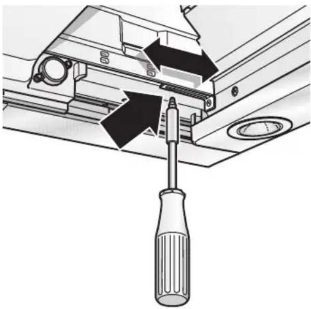
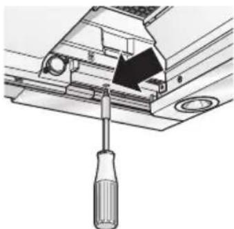
☐ If the extractor hood is to be installed further back in the cupboard, the stops for the filter drawer can be moved forwards.
☐ To do this, undo the screws, move the stops and retighten the screws.
natural_image
Diagram of a screwdriver inserted into a mechanical component, showing tool path and mounting detail (no text or symbols)Weight in kg:
| Exhaust air Circulating air | |
| 13,0 13,5 | |
We reserve the right to construction changes within the context of technical development.
Moving the operating unit:
See Operating instructions.
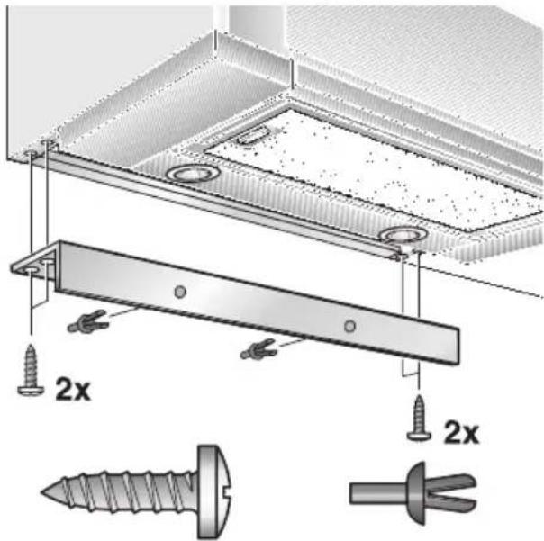
Attaching the handle moulding:
A handle moulding must be attached to the filter drawer.
This handle moulding may be a wooden strip which matches the kitchen units or a handle moulding available as an optional accessory (see optional accessories on the back page).
- Using the enclosed template Ⓗ mark the attachment points on the wooden strip and make holes with a bradawl. When you drill:
2 mm dia - max. 10 mm in depth.
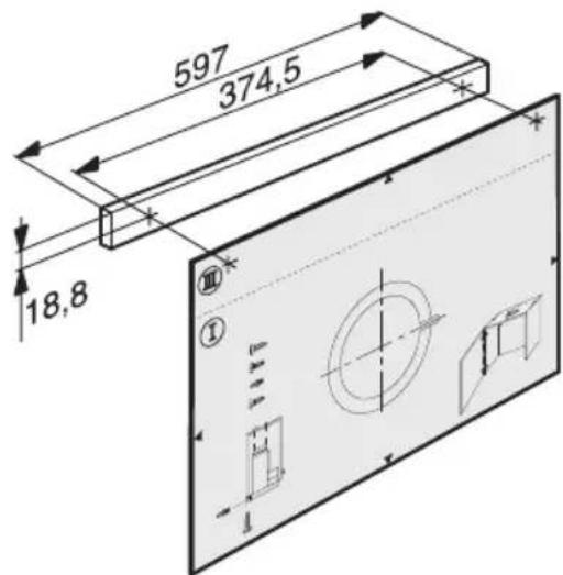
text_image
597 374,5 18,8- Align handle moulding and screw to the appliance.
Do not pinch the ribbon cable.
natural_image
Technical illustration of a mechanical assembly with screw and housing components (no text or symbols)Electrical connection
WARNING: THIS APPLIANCE MUST BE EARTHED
IMPORTANT: Fitting a Different Plug:
The wires in the power cord are colour-coded as follows:
Green and Yellow – Earth
Blue - Neutral
Brown - Live
If you fit your own plug, the colours of these wires may not correspond with the identifying marks on the plug terminals.
Proceed as follows:
-
Connect the green and yellow (Earth) wire to the terminal in the plug marked 'E' or with the symbol (≡), or coloured green or green and yellow.
-
Connect the blue (Neutral) wire to the terminal in the plug marked 'N' or coloured black.
-
Connect the brown (Live) wire to the terminal marked 'L', or coloured red.
The extractor hood may be connected to a correctly installed earthed socket only. Attach the earthed socket near the extractor hood in an accessible position.
☐ The earthed socket should be connected via its own power circuit.
⚠️If appliances do not feature the OFF delay function, the indicator may start flashing when the extractor hood has been switched off for several hours via a separate switch, even though the grease filters are not yet saturated.
(See instructions for use, section on filter and maintenance).
Electrical specifications:
These can be found on the rating plate inside the appliance following removal of the filter frames.
⚠️Before carrying out repairs, always isolate the appliance.
Length of the connection cable: 1.30 m.
If permanent connection is required:
The extractor hood may only be connected by an electrician registered with the local electricity board.
A disconnecting device must be provided on the installation side. Switches with a contact opening of more than 3 mm and all-pole disconnection are regarded as disconnecting devices. These include LS switches and contactors.
This extractor hood complies with EU regulations on interference suppression.
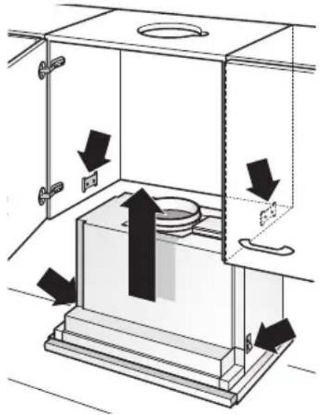
Removal from the wall cupboard
- Disconnect from power.
- Disconnect pipes.
- Remove filters.
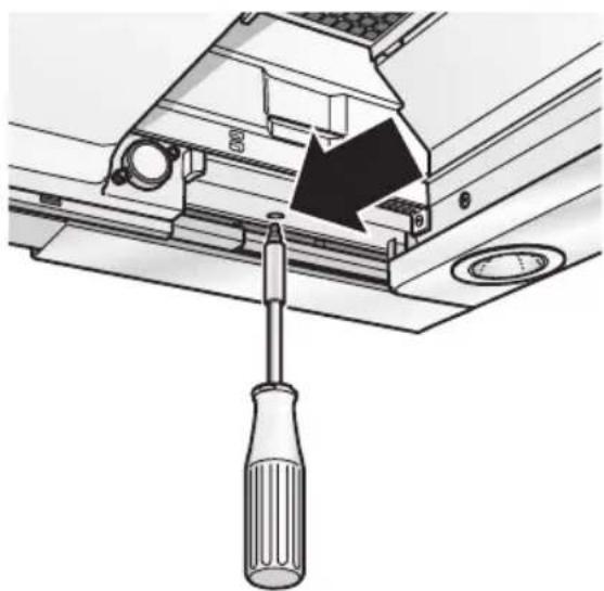
- Undo right and left fixing screws until the extractor hood cannot drop any further.
natural_image
Mechanical assembly diagram showing a screwdriver inserted into a component with a black arrow indicating direction (no text or symbols present)⚠ Do not lift the extractor hood when undoing the fixing screws.
- Raise the extractor hood briefly until the fixing lugs detach and the appliance can be lowered.
⚠️ Fastening screws may project. When raising the extractor hood, do not force in the filter drawer.
- Preparing for re-installation:
Screw in the left and right fixing screws until the lugs are pressed out at the sides.
Mode d'emploi:
natural_image
Technical line drawing of a cabinet interior showing door, shelf, and vent (no text or symbols)text_image
Hand-drawn interface with icons for zoom, refresh, and navigation controlsAspiration intensive:
text_image
Diagram of a control panel with labeled buttons and a finger pointing to it, showing icons for alarm, function, and display.text_image
Control panel with indicator lights, buttons, and function buttons labeled with icons and symbolsnatural_image
Technical diagram of a mechanical assembly with arrows indicating force or movement (no text or symbols present)natural_image
Technical diagram of a mechanical device with internal components and directional arrows indicating flow or movement (no text or symbols)natural_image
Diagram of a computer ventilation system showing airflow path and component placement (no text or labels)natural_image
Illustration of a magnifying glass with a handle and circular lens (no text or symbols)natural_image
Illustration of a hand holding a screwdriver with a circular component and an arrow indicating rotation (no text or symbols)text_image
Technical diagram showing a mechanical assembly with labeled components and a screw, likely illustrating a gear or mounting mechanism.natural_image
Diagram of a server rack with an inset showing internal components and directional arrows (no text or symbols)natural_image
Diagram of a mechanical or structural component with directional arrows indicating flow or force, no text or symbols present.natural_image
Diagram of a laboratory apparatus with arrows indicating flow or movement, no text or symbols presentnatural_image
Diagram of a screwdriver inserted into a mechanical component, showing a black arrow indicating the insertion direction (no text or symbols present)natural_image
Diagram of a screwdriver inserted into a mechanical component, showing tool path and mounting detail (no text or symbols)Poids en kg:
natural_image
Technical diagram of a mechanical assembly with screw fasteners and a separate screw component (no text or labels)natural_image
Diagram of a screwdriver inserted into a mechanical component, showing a black arrow indicating the tool (no text or symbols present)text_image
Weather icon buttons for solar, moon, and night symbols with corresponding icons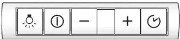
text_image
Control panel with lightbulb icon, radio button, minus sign, plus and download iconsnatural_image
Technical line drawing of a cabinet interior showing door, shelf, and vent (no text or symbols)text_image
Hand-drawn interface with icons for addition, zoom, and function buttons, featuring a finger pointing to the number 'F' on a finger.Ventilatorstanden:
text_image
+ - A L ≈text_image
Diagram showing a hand holding a device with icons and numbers, likely indicating status or functiontext_image
Control panel with indicator lights, buttons, and three finger icons for display or function□ Fabrieksinstelling: 7.
□ Laagste instelling: □.
☐ Hoogste instelling: 9.
Filter en onderhoud
Vetfilters:
natural_image
Technical diagram of a mechanical component with arrows indicating assembly or force direction (no text or symbols present)natural_image
Technical diagram of a mechanical device with internal components and directional arrows indicating flow or movement (no text or symbols)natural_image
Diagram of a computer monitor with ventilation slots and an open tray, showing internal structure and arrows indicating airflow direction (no text or symbols)natural_image
Illustration of a magnifying glass with a handle and circular lens (no text or symbols)Let op: plugfitting.
natural_image
Illustration of a hand holding a tool with a circular component and an arrow indicating rotation (no text or symbols)text_image
Technical diagram showing a mechanical assembly with labeled components and a screw, including a bolt and adjustment knob.natural_image
Diagram of a server rack with an inset magnified view showing internal components (no text or symbols)natural_image
Three schematic diagrams showing airflow patterns between structural elements, with no visible text or symbols.natural_image
Diagram of a mechanical or fluidic system with directional arrows indicating flow or movement, no text or symbols present.natural_image
Diagram of a laboratory apparatus with arrows indicating flow or movement, no text or symbols presentnatural_image
Mechanical assembly diagram showing a screwdriver inserted into a component, with no visible text or symbolsnatural_image
Diagram of a screwdriver inserted into a mechanical component, showing tool path and mounting detail (no text or symbols)Gewicht in kg:
natural_image
Technical diagram of a mechanical assembly with screw and housing components, no visible text or symbolsnatural_image
Mechanical assembly diagram showing a screwdriver inserted into a component with a black arrow indicating direction (no text or symbols present)text_image
Weather and weather icons including sun, moon, +, and alarm symbol
text_image
Control panel with lightbulb icon, radio button, minus sign, plus and down iconsnatural_image
Technical line drawing of a cabinet interior showing door, shelf, and lid components (no text or symbols)text_image
Hand-drawn interface with icons for zoom, settings, and function buttonstext_image
Diagram showing a hand holding a device with icons for alarm, function, and display, likely indicating status or function.text_image
Control panel with indicator lights, buttons, and function buttons labeled with symbols like '灯' (light), '一' (one), 'E' (electricity), '+', 'F', and '✓'natural_image
Technical diagram of a mechanical assembly with arrows indicating force or movement (no text or symbols present)natural_image
Technical diagram of a mechanical device with internal components and directional arrows indicating flow or movement (no text or symbols)natural_image
Diagram of a computer ventilation system showing airflow path and component placement (no text or labels)natural_image
Illustration of a magnifying glass with a handle and circular lens (no text or symbols)natural_image
Illustration of a hand holding a screwdriver with a circular component above it, showing a curved arrow (no text or symbols)text_image
Technical diagram showing a mechanical assembly with labeled components and a screw, likely illustrating a gear or mounting mechanism.natural_image
Diagram of a server rack with an inset showing internal components and directional arrows (no text or symbols)natural_image
Diagram of a mechanical or fluidic system with directional arrows indicating flow or movement, no text or symbols present.natural_image
Diagram of a laboratory apparatus with arrows indicating flow or movement, no text or symbols presentnatural_image
Diagram of a screwdriver inserted into a mechanical device component, showing a black arrow indicating the insertion direction (no text or symbols present)natural_image
Diagram of a screwdriver inserted into a mechanical component, showing tool path and mounting detail (no text or symbols)Peso in kg:
natural_image
Technical illustration of a mechanical assembly with screw fasteners and a separate screw (no text or symbols)natural_image
Mechanical assembly diagram showing a screwdriver inserted into a component with a black arrow indicating direction (no text or symbols present)text_image
Weather icon buttons including sun, moon, and alarm symbol with numeric values and plus/minus signs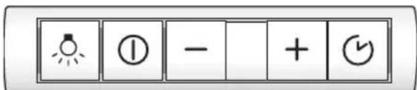
text_image
Control panel with lightbulb icon, radio button, minus sign, plus and down iconsnatural_image
Technical line drawing of a cabinet interior showing door, shelf, and vent (no text or symbols)text_image
Hand-drawn interface with icons for addition, summing, rotation, and navigation controlstext_image
Diagram showing a hand gesture pointing to four labeled buttons with icons: one with a sun icon, one with a circle, one with minus sign, and one with a number 8.text_image
Control panel with indicator lights, buttons, and function buttons labeled with icons and symbolsnatural_image
Technical diagram of a mechanical assembly with arrows indicating force or movement (no text or symbols present)natural_image
Technical diagram of a mechanical device with internal components and directional arrows indicating flow or movement (no text or symbols)natural_image
Diagram of a computer ventilation system showing airflow path and component placement (no text or labels)natural_image
Illustration of a magnifying glass with a handle and circular lens (no text or symbols)natural_image
Illustration of a hand holding a screwdriver with a curved arrow pointing to a circular component (no text or symbols)text_image
Technical diagram showing a mechanical assembly with labeled components and a screw, likely illustrating a mounting or mounting mechanism.natural_image
Diagram of a server rack with an inset showing internal components and directional arrows (no text or symbols)natural_image
Diagram of a mechanical or fluidic system with directional arrows indicating flow or movement (no text or symbols present)natural_image
Technical diagram of a laboratory apparatus with arrows indicating flow or movement, no visible text or symbolsnatural_image
Technical illustration of a screwdriver inserted into a mechanical device component (no text or symbols visible)natural_image
Diagram of a screwdriver inserted into a mechanical component, showing tool path and mounting detail (no text or symbols)Peso en kg:
natural_image
Technical diagram of a mechanical assembly with screw and plate components, no text or symbols presentConexión eléctrica
natural_image
Mechanical assembly diagram showing a screwdriver inserted into a bracket with a black arrow indicating direction (no text or symbols present)text_image
Weather and solar panel icons with symbols for sun, moon, and polar bearnatural_image
Technical line drawing of a cabinet or enclosure with open door, internal shelf, and cylindrical component (no text or symbols)text_image
Hand-drawn interface with icons for zoom, refresh, and navigation controlsFases da turbina:
text_image
Diagram showing a hand holding a spray gun next to four labeled buttons with icons and symbols: sun, circle, minus sign, and letter 'B'.text_image
Control panel with icons for lighting, minus sign, plus sign, and function buttonsnatural_image
Technical diagram of a mechanical assembly with arrows indicating force or movement (no text or symbols present)natural_image
Technical diagram of a mechanical device with internal components and directional arrows indicating flow or movement (no text or symbols)natural_image
Diagram of a computer ventilation system showing airflow path and component placement (no text or labels)natural_image
Illustration of a magnifying glass with a handle and circular lens (no text or symbols)- Substituir a lâmpada de halogéneo (lâmpada de halogéneo corrente no mercado, 12 Volt, máx. 20 Watt, casquilho G4).
natural_image
Illustration of a hand holding a cable with a magnified inset showing a device inside (no text or symbols)text_image
Technical diagram of a mechanical assembly with labeled components and screwdriver, showing assembly steps and component placement.natural_image
Diagram of a server rack with an inset close-up showing internal components (no text or symbols)natural_image
Diagram of a mechanical or structural component with directional arrows indicating flow or force, no text or symbols present.natural_image
Diagram of a laboratory apparatus with arrows indicating flow or movement, no text or symbols presentnatural_image
Mechanical assembly diagram showing a screwdriver inserted into a component, with no visible text or symbolsnatural_image
Technical illustration of a screwdriver inserted into a mechanical component (no text or symbols visible)Peso em kg:
natural_image
Technical diagram of a mechanical assembly with screw fasteners and housing (no text or symbols)Ligação eléctrica
natural_image
Mechanical assembly diagram showing a screwdriver inserted into a component (no text or symbols visible)text_image
Weather icon set with sun, moon, minus sign, plus button, and play button symbols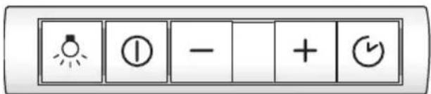
text_image
Control panel with lightbulb icon, radio button, minus sign, plus and down icons- Manter premida a tecla Ⓓ.
- Premir a tecla ○ 📋 durante cerca de 3 seg.
Online-Shop: www.siemens-eshop.com