K12 - Speaker QSC - Free user manual and instructions
Find the device manual for free K12 QSC in PDF.

User questions about K12 QSC
0 question about this device. Answer the ones you know or ask your own.
Ask a new question about this device
Download the instructions for your Speaker in PDF format for free! Find your manual K12 - QSC and take your electronic device back in hand. On this page are published all the documents necessary for the use of your device. K12 by QSC.
USER MANUAL K12 QSC
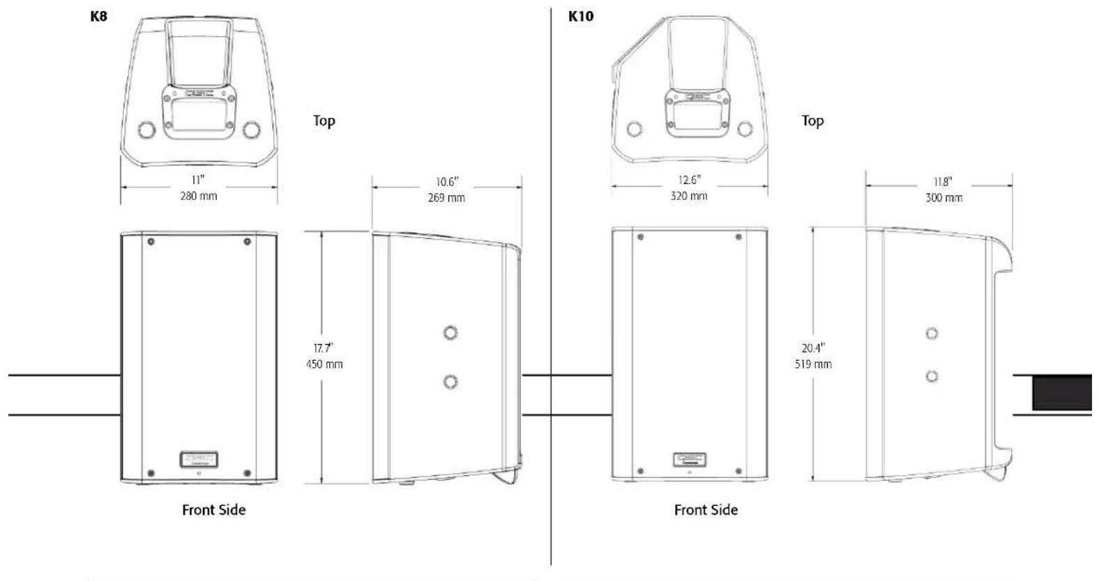
K8 - 105° 1000 W active 8" (200 mm) 2-way loudspeaker system
K10 - 90° 1000 W active 10" (250 mm) 2-way loudspeaker system
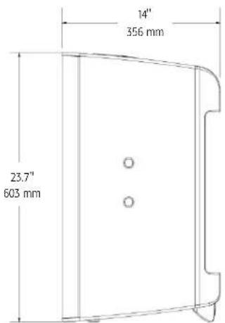
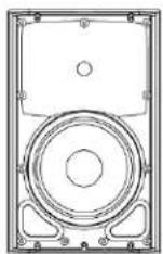
K12 - 75° 1000 W active 12" (300 mm) 2-way loudspeaker system
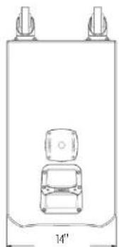
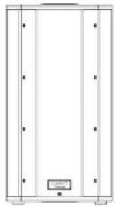
KSub - Dual 12" (300 mm) 1000 W active 4th-order bandpass subwoofer system
natural_image
Technical line drawing of a speaker or audio device casing with no visible text or symbols
natural_image
Technical line drawing of a speaker or audio device casing with concentric circles and mounting brackets (no text or symbols)
natural_image
Technical line drawing of a speaker with two concentric circles and mounting brackets (no text or symbols)
natural_image
Pure architectural or mechanical diagram with vertical panels and a small labeled component (no text or symbols)IMPORTANT SAFETY PRECAUTIONS AND EXPLANATION OF SYMBOLS

WARNING!

CAUTION: TO REDUCE THE RISK OF ELECTRIC SHOCK, DO NOT REMOVE THE AMPLIFIER COVER. NO USER-SERVICEABLE PARTS INSIDE. REFER SERVICING TO QUALIFIED PERSONNEL.

The lightning flash with the arrowhead symbol within an equilateral triangle is intended to alert the user to the presence of uninsulated "dangerous" voltage within the product's enclosure that may be of sufficient magnitude to constitute a risk of shock to humans.

The exclamation point within an equilateral triangle is intended to alert the user to the presence of important operation and maintenance (servicing) instructions in this manual.
- Read these instructions.
-
Keep these instructions.
-
Heed all warnings.
-
Follow all instructions.
-
WARNING: To prevent fire or electric shock, do not expose this equipment to rain or moisture. Do not use this apparatus near water.
-
Clean only with a dry cloth.
-
Allow a minimum of 6" (152 mm) clearance behind cabinet for convection cooling. Keep anything that might restrict airflow from the rear of the enclosure (i.e. draperies, fabric, etc.). Do not block any ventilation opening. This product contains an internal power amplifier that produces heat.
-
Do not install near any heat sources such as radiators, heat registers, stoves, or other apparatus (including amplifiers) that produce heat.
-
Do not defeat the safety purpose of the grounding-type plug on the three-pronged "Edison" style power cable. The grounding plug has two blades and a grounding prong. The third prong is provided for your safety. If the provided plug does not fit your outlet, consult an electrician for the replacement of the obsolete outlet. Do not cut off the grounding plug or use an adapter that breaks the grounding circuit. This apparatus must be properly grounded for your safety.
-
Protect the power cord from being walked on or pinched, particularly plugs, convenience receptacles, and the point where they exit from the apparatus.
-
The appliance coupler is the AC mains disconnect and should remain readily operable after installation.
-
Use only attachments/accessories specified by QSC Audio Products, LLC.
-
Use only with hardware, brackets, and components sold with the apparatus or by QSC Audio Products, LLC.
-
Unplug the apparatus during lightning storms or when unused for long periods of time.
-
Refer all servicing to qualified service personnel. Servicing is required when the apparatus has been damaged in any way, such as power supply cord or plug is damaged, liquid has been spilled or objects have fallen into the apparatus, the apparatus has been exposed to rain or moisture, does not operate normally or has been dropped.
-
Before placing, installing, rigging or suspending any loudspeaker product, inspect all hardware, suspension, cabinets, transducers, brackets and associated equipment for damage. Any missing, corroded, deformed, or non-load rated component could significantly reduce the strength of the installation and should be immediately corrected. Use only hardware which is rated for the loading conditions of the installation and any possible short-term unexpected overloading. Never exceed the rating of the hardware or equipment.
-
Consult a licensed, professional engineer when any doubt or questions arise regarding a physical equipment installation.
-
The appliance shall not be exposed to dripping or splashing and no objects filled with liquids, such as vases, shall be placed on the apparatus.
Warranty (USA only; other countries, see your dealer or distributor)
QSC Audio Products 3 Year Limited Warranty
QSC Audio Products, LLC ("QSC") guarantees its products to be free from defective material and/or workmanship for a period of three (3) years from the date of sale and will replace defective parts and repair malfunctioning products under this warranty when the defect occurs under normal installation and use – provided the unit is returned to our factory or one of our authorized service stations via prepaid transportation with a copy of proof of purchase (i.e., sales receipt). This warranty provides that the examination of the returned product must indicate, in our judgement, a manufacturing defect. This warranty does not extend to any product which has been subjected to misuse, neglect, accident, improper installation, or where the date code has been removed or defaced. QSC shall not be liable for incidental and/or consequential damages. This warranty gives you specific legal rights. This limited warranty is freely transferable during the term of the warranty period.
Customer may have additional rights, which vary from state to state.
In the event that this product was manufactured for export and sale outside of the United States or its territories, then this limited warranty shall not apply. Removal of the serial number on this product, or purchase of this product from an unauthorized dealer will void this limited warranty.
Periodically, this warranty is updated. To obtain the most recent version of QSC's warranty statement, please visit www.qscaudio.com.
Contact us at 800-854-4079 or visit our website at www.qscaudio.com.
FCC Statement
NOTE: This equipment has been tested and found to comply with the limits for a Class B digital device, pursuant to Part 15 of the FCC Rules.
These limits are designed to provide reasonable protection against harmful interference in a residential installation. This equipment generates, uses and can radiate radio frequency energy and, if not installed and used in accordance with the instructions, may cause harmful interference to radio communications. However, there is no guarantee that interference will not occur in a particular installation. If this equipment does cause harmful interference to radio or television reception, which can be determined by turning the equipment off and on, the user is encouraged to try to correct the interference by one or more of the following measures:
- Reorient or relocate the receiving antenna.
- Increase the separation between the equipment and receiver.
- Connect the equipment into an outlet on a circuit different from that to which the receiver is connected.
- Consult the dealer or an experienced radio/TV technician for help.
Package Contents
K8, K10, K12
(1) Loudspeaker system
(1) Locking power cable
(1) Euro-style Connector Plug, 3-pin
(1) K Series Hookup Drawings
(1) Warning Information Sheet
KSub
(1) Subwoofer system
(1) Locking power cable
(1) Euro-style Connector Plug, 3-pin
(1) M20 threaded loudspeaker pole
(1) K Series Hookup Drawings
(1) Warning Information Sheet
Features
K8
- ABS enclosure
- Steel grille
- Front power LED
- Cast aluminum handles
- Power module
- M10 installation points
- M5 yoke attachment points
- Tilt-Direct™ dual angle pole socket
- Slip-resistant feet
text_image
Technical diagram of a device with numbered components, likely an electronic or mechanical assembly.K10
- ABS enclosure
- Steel grille
- Front power LED
- Cast aluminum handles
- Power module
- M10 installation points
- M5 yoke attachment points
- Tilt-Direct™ dual angle pole socket
- Slip-resistant feet
text_image
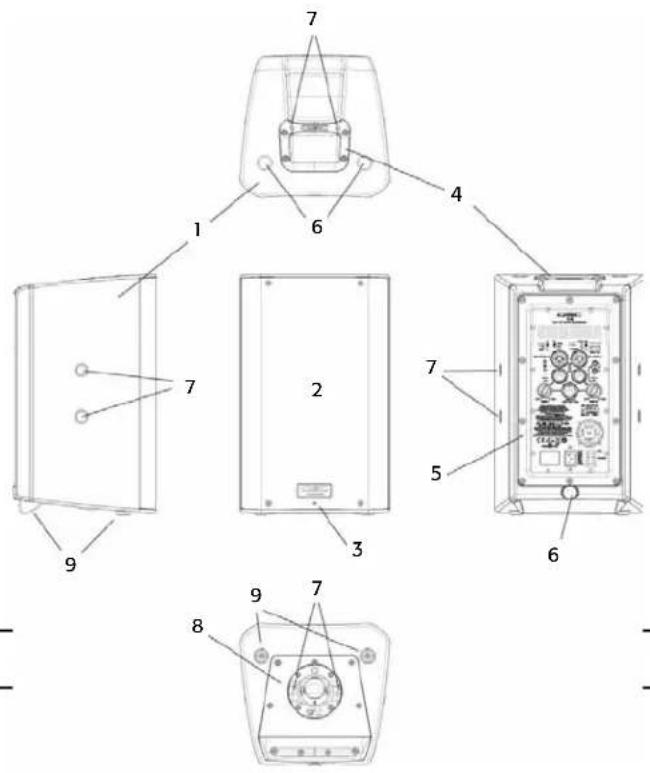
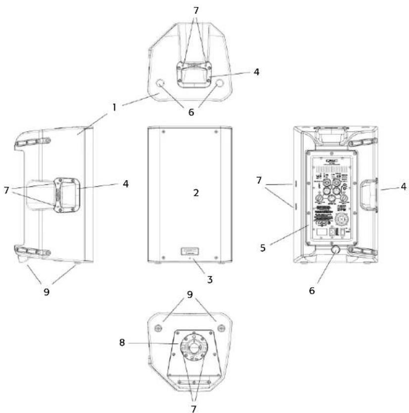
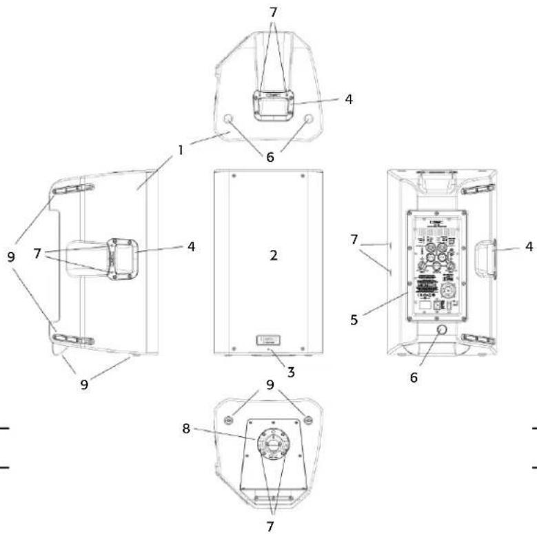
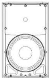
Technical diagram of a device's internal components with numbered labels for identification.K12
- ABS enclosure
- Steel grille
- Front power LED
- Cast aluminum handles
- Power module
- M10 installation points
- M5 yoke attachment points
- Tilt-Direct™ dual angle pole socket
- Slip-resistant feet
text_image
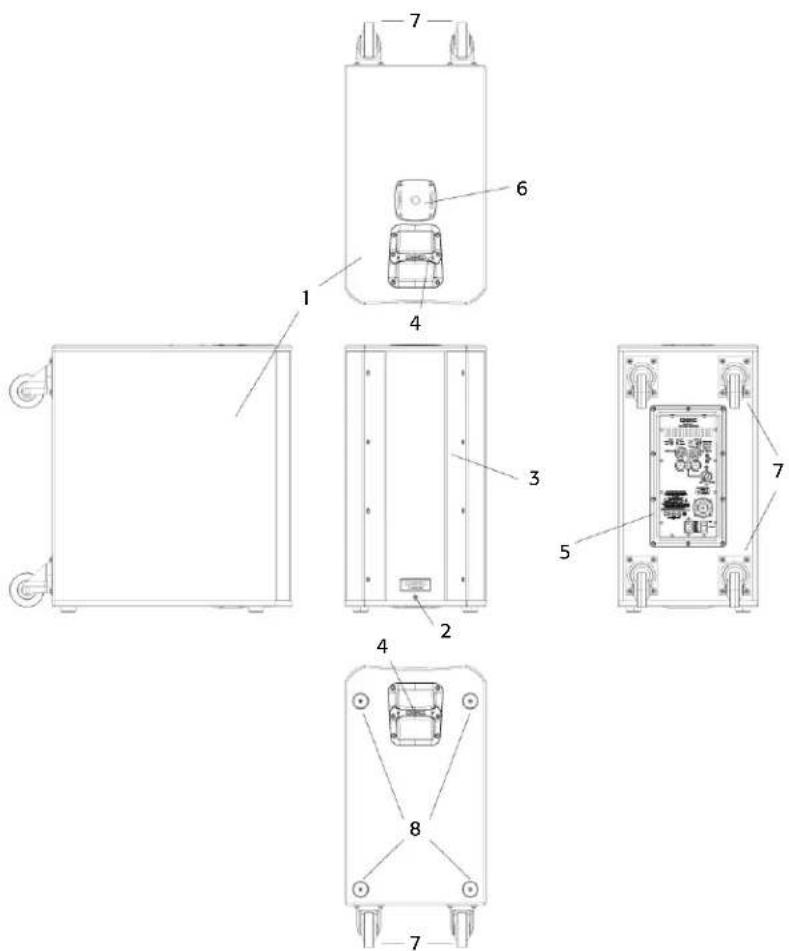
Technical diagram of a device with numbered components for identification and assembly reference.KSub
- Birch plywood enclosure
- Front power LED
- Acoustic port
- Cast aluminum handles
- Power module
- M20 threaded pole receptacle
- 3" heavy duty casters
- Slip-resistant feet
text_image
Technical diagram of an electrical enclosure with labeled components and exploded viewsApplications
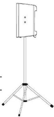
The K Series has been primarily designed for portable audio reinforcement. This includes a variety of uses in reinforcement for entertainers and presenters. The K8, K10 and K12 are all designed to perform well on their own in full-range audio. They can be used singly, in stereo pairs or in distributed or delayed systems. They perform extraordinarily well as both main reinforcement systems and as floor monitors (K10 and K12 only). (Figure 1)
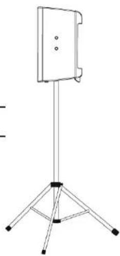
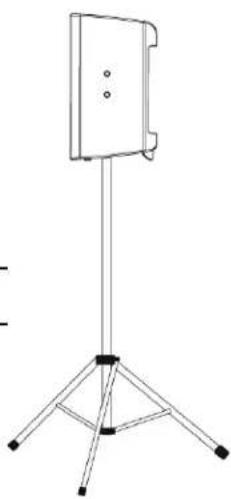
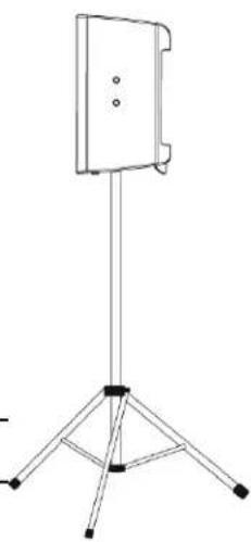
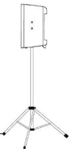
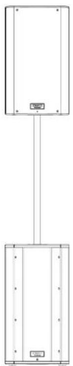
The K8, K10, and K12 are all equipped with a 35 mm pole socket that allows use on a speaker stand or on a pole over a subwoofer. The pole socket features the QSC Tilt-Direct™ system for tilting the enclosures down 7.5 degrees while on the pole. (Figure 2)
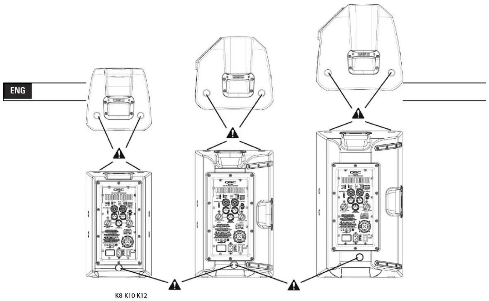
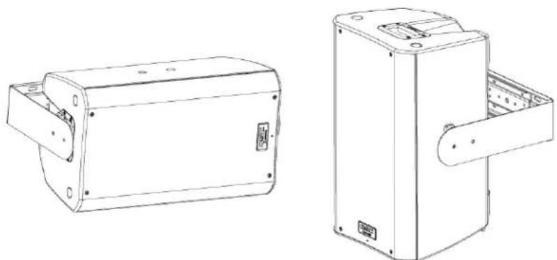
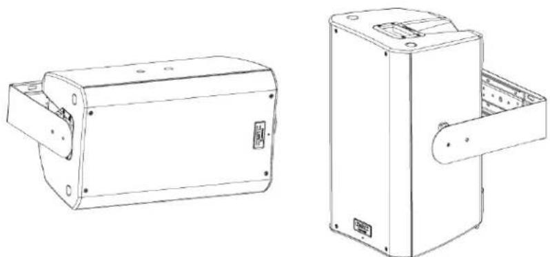
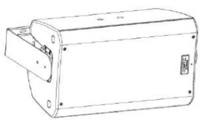
The K8, K10 and K12 also have features designed for various suspension methods. They feature M10 threaded inserts for suspension with eyebolts. There are also yoke accessories (model numbers: K8 YOKE, K10 YOKE, K12 YOKE) for each model that can mount either to the sides of the cabinet or to the top and bottom. These yokes allow for rigid mounting to structures and rotation of the speaker system. (Figure 3)
ENG
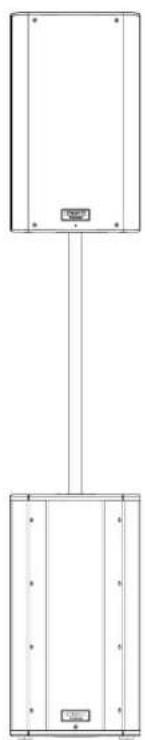
For extra low-frequency extension and enhancement, the KSub is perfectly matched to the rest of the K Series. The K8, K10 and K12 all have a selectable high-pass filter for use with the subwoofer. The KSub includes a fixed low-pass filter so it will accept full-range input.
The KSub has four large casters for maximum portability. The pole socket on the top of the enclosure is fitted with an M20 threaded insert. The included speaker pole screws into the socket for a secure fit. (Figure 4)
natural_image
Technical line drawing of a mechanical housing or enclosure with mounting holes and internal components (no text or symbols)- Figure 1 -
natural_image
Line drawing of a simple stand with three legs and a central panel (no text or symbols)
natural_image
Line drawing of a tripod-mounted stand with a flat top and three legs (no text or symbols)- Figure 2 -

natural_image
Technical line drawings of two mechanical components with mounting holes and internal compartments (no text or symbols)- Figure 3 -

natural_image
Pure electrical circuit lines without any symbols- Figure 4 -
Installation

Before placing, installing, rigging, or suspending any speaker product, inspect all hardware, suspension, cabinets, transducers, brackets and associated equipment for damage. Any missing, corroded, deformed, or non-load rated component could significantly reduce the strength of the installation or placement. Any such condition severely reduces the safety of the installation and should be immediately corrected. Use only hardware which is rated for the loading conditions of the installation and any possible short-term, unexpected overloading.
Never exceed the rating of the hardware or equipment.
Consult a licensed, professional engineer regarding physical equipment installation. Ensure that all local, state and national regulations regarding the safety and operation of loudspeakers and related equipment are understood and adhered to.
Recommended Deployment
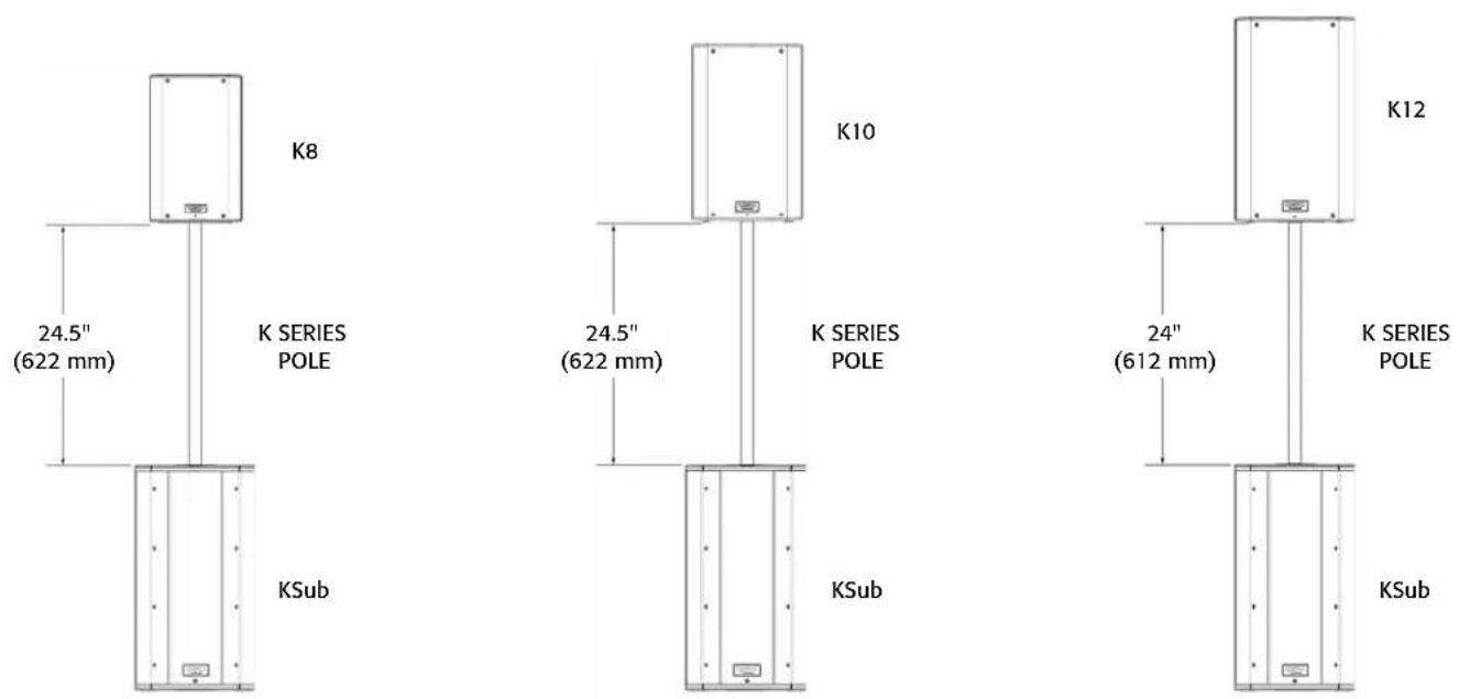
K8: The K8 was designed to sit on the floor, stage, subwoofer enclosure, be suspended, or be pole mounted on a 35 mm diameter loudspeaker support pole. When pole-mounted to the KSub, pole length must not exceed 31 inch (787 mm).
K10: The K10 was designed to sit on the floor, stage, subwoofer enclosure, be suspended, or be pole mounted on a 35 mm diameter loudspeaker support pole. When pole-mounted to the KSub, pole length must not exceed 28.5 inch (724 mm).
K12: The K12 was designed to sit on the floor, stage, subwoofer enclosure, be suspended, or be pole mounted on a 35 mm diameter loudspeaker support pole. When pole-mounted to the KSub, pole length must not exceed 26.5 inch (673 mm).
KSub: The KSub was designed to sit on the floor or on the stage. A threaded pole cup on the top of the enclosure accepts a M20 threaded 35 mm loudspeaker mounting pole. There are additional M20 speaker poles available from third party suppliers. Rubber feet on the enclosure's bottom help to minimize enclosure movement during operation. Do not pole mount or stack more than one enclosure on top of the KSub enclosure. As the casters will wear during normal use, it may be required to insert small foam pieces between the wheels and frames to minimize rattling at high output levels.

K8 WARNING! Do not use a loudspeaker support pole longer than 31 inch (787 mm) when supported by the KSub subwoofer.

K10 WARNING! Do not use a loudspeaker support pole longer than 28.5 inch (724 mm) when supported by the KSub subwoofer.

K12 WARNING! Do not use a loudspeaker support pole longer than 26.5 inch (673 mm) when supported by the KSub subwoofer.
Integrated Suspension Points (suspended installations)
The K8, K10 and K12 enclosures each feature three load-rated M10 installation points.
As shipped from the factory, each pick point has a rubber plug installed to retain the sleek look of the enclosure. These installation points are designed for use with the eyebolts included in the available accessory kit, model number K SERIES M10 KIT. The installation points may also be used with any forged shoulder eyebolt with an M10 thread, provided the length of the thread is no more than 0.8 inch (20 mm).

Ensure all pick-point fasteners are installed and correctly tightened in order to maintain enclosure's rated strength. Use either QSC's M10 forged shoulder eye bolts contained in K SERIES M10 KIT or an M10 forged shoulder eyebolt with a thread length no more than 0.8 inch (20 mm). Contact QSC Technical Services department for complete information.
text_image
ENG K8 K10 K12Cooling in Installed Applications
This is a self-powered loudspeaker containing an internal power amplifier that produces heat. Allow a minimum of 6" (152 mm) clearance at cabinet back for convection cooling. Keep anything that might restrict airflow away from the rear of the enclosure (i.e draperies, fabric, etc...).

Do not install enclosures with their rear panels exposed to direct sunlight. Direct sunlight will heat the amplifier module and reduce its ability to produce full output. Install sunshades if the application merits. Maximum ambient temperature for full performance to specification is 50^ C ( 122^ F). Do not install enclosures where exposed to rain or other water sources. The enclosure is not weatherproof. Outdoor installations must provide protection from the elements.
AC Mains
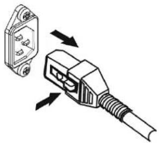
Connect AC power to the IEC socket on the back of the amplifier by locating the IEC connector-end of the AC power cord and inserting it fully into the IEC inlet on the power amplifier module. NOTE: Turn off the AC power switch before connecting AC power.
The V-LOCK power cord has a special latching feature to prevent the power cord from being unintentionally removed. The IEC plug and socket are both blue in color so the power cord can be identified as a K Series loudspeaker cord. If the QSC supplied cord becomes lost or damaged, a standard replacement 18 gauge IEC power cord may be used. However, the latching system will only function with a V-LOCK power cord available from QSC Audio Products, LLC.
natural_image
Diagram of a plug with two pins and a connector, showing directional arrows indicating assembly or connection (no text or symbols present)The K Series is fed by a universal power supply. This power supply is capable of operating the system with input AC power voltages ranging from 100 - 240 VAC at 50 - 60 Hz.

Use only the power cable that is correct for your location.
You may discard any other power cables, find an appropriate recycling opportunity or keep them if travel to other regions with the K Series product is likely.
AC Mains Disconnection
Turn the AC power switch to the off position. To remove the AC mains cord, grasp the IEC connector's plastic body, press the yellow latch release button and pull, removing the connector from the socket.
Power Switch
Push in on the top of the rocker switch to apply AC mains power to the powered loudspeaker. Push in on the bottom of the rocker switch to turn the powered loudspeaker off.
When turned on, the green STANDBY indicator LED and the red LIMIT (limiter) indicator LED on the rear panel will illuminate; after a few seconds the red LIMIT indicator and the green STANDBY will extinguish, and the blue POWER indicator LED will illuminate.
Rear LED POWER Indicator
The blue LED POWER indicator on the rear panel will illuminate when the AC Power switch is in the "ON" position, the unit is not in standby, the AC mains power cord is connected properly, and the AC mains are functioning properly. The rear LED POWER indicator will extinguish when the AC Power switch is in the "off" position, AC mains power has been removed from the loudspeaker, or the amplifier enters standby.
If the rear LED POWER indicator does not illuminate when the Power switch is placed in the "on" position during the first 5 minutes of power being applied, verify the AC mains line cord is properly attached to the loudspeaker and plugged into the AC outlet. Verify the outlet is functioning properly.
If the AC mains cordset is serviceable and the AC mains outlet is operating properly, but the loudspeaker fails to operate, the loudspeaker may require servicing. Contact QSC's Technical Services department.
System Power Sequencing

Proper power turn on/turn off sequencing can help to prevent unexpected sounds from being produced by the system (pops, clicks, thumps). These unintended sounds can be unpleasant and take away from the overall professionalism of the presentation. Always follow the rule that speakers are "last on, first off".
Power On Sequence: Bring the output level control of the mixer (or other audio source) feeding your speakers to its minimum position. Turn on all source devices (CD players, mixers, instruments), turn on subwoofer, then turn on the "top-boxes" (K8, K10, K12). The level controls on your mixer may now be brought up.
Power Off Sequence: Turn off "top boxes," turn off subwoofer, then turn off all source devices.
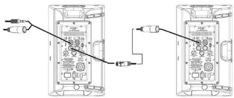
If a K Series speaker is being driven from the output of another K Series unit, it should be turned on after the unit feeding it signal, and turned off before the unit feeding signal.
Input Connections
K8, K10, K12
flowchart
graph TD
    A["Channel A MIC/Line Input Combination XLR-M and 1/4" Phone Jack"] --> B["MIC/LINE IN A"]
    B --> C["Channel A MIC Level Yellow LED Indicator"]
    B --> D["Channel A MIC/Line Level Switch"]
    B --> E["Channel A Green Signal Present LED"]
    F["Channel B Line Input Combination XLR-M and 1/4" Phone Jack"] --> G["Signal L"]
    G --> H["Channel B Line Input Phono (RCA) Jacks"]
    G --> I["Channel B Green Signal Present LED"]
    J["Channel A Gain"] --> K["GAIN A"]
    K --> L["OFF +10dB"]
    L --> M["LINE OUT (POST GAIN - MIX)"]
    M --> N["OFF +10dB"]
    N --> O["GAIN B"]
    O --> P["Channel B Gain"]
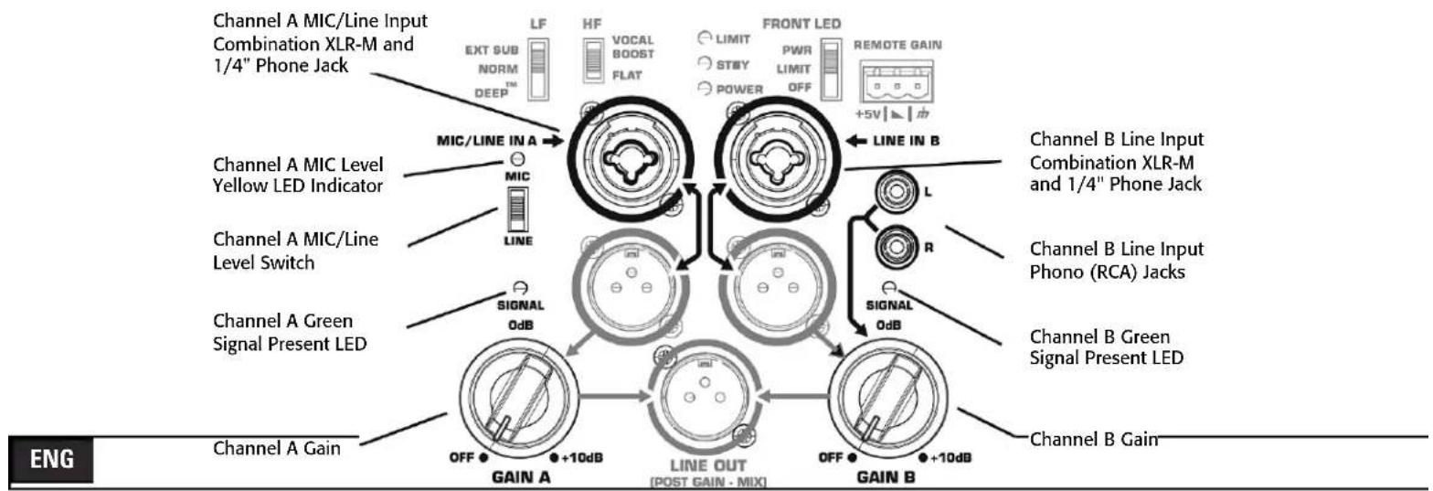
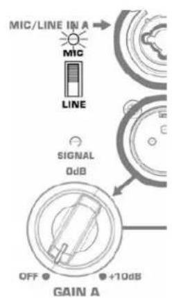
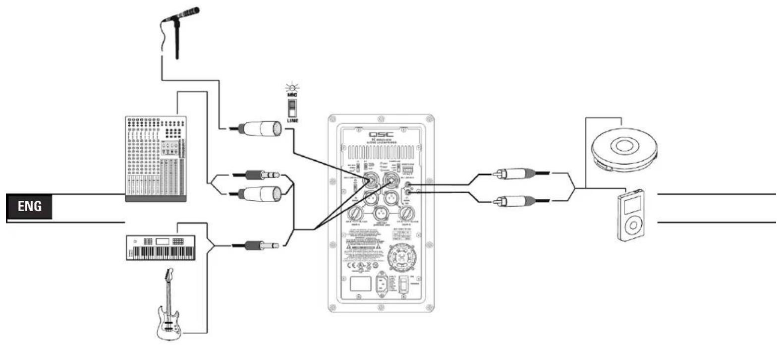
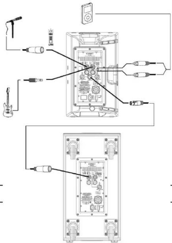
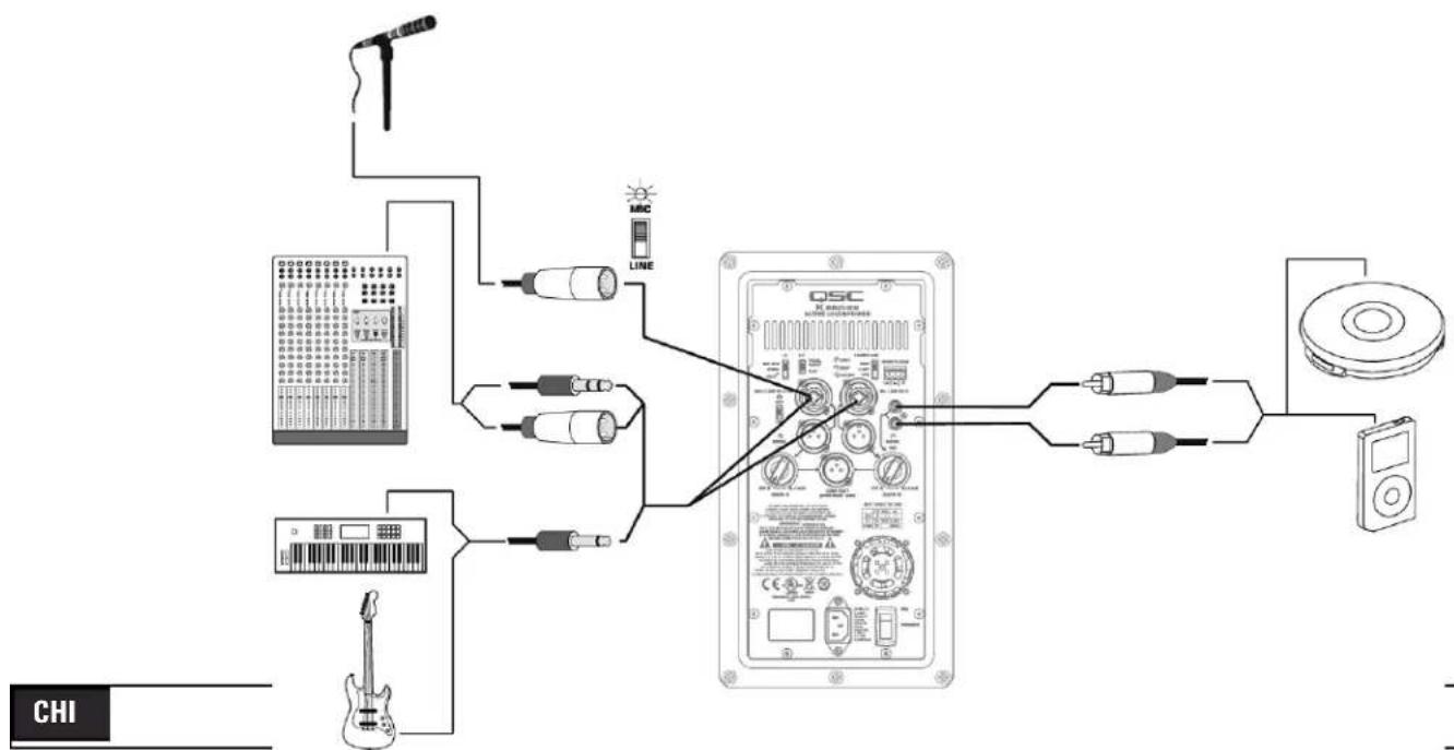
The K8, K10 and K12 are designed to accept MIC Level and Line Level inputs with several different connectors. There are three input connection points on the input panel. Channel A will accept MIC or Line Level inputs by connecting a male XLR cable or a male 1/4" phone cable (either TS or TRS type may be used). For MIC Level, the MIC/LINE selector switch must be in the "MIC" position. (Figure 5) When the selector switch is in the MIC position, activating the MIC Pre-amp, the yellow MIC level LED indicator will turn on. The MIC setting should only be used if a microphone is connected directly to the MIC/LINE input. Note that the input does not provide phantom power. The LINE setting should be used for most other audio inputs. (Figure 6)

The MIC setting should only be used if a microphone is connected directly to the MIC/LINE input. Using the MIC setting for other purposes may introduce distortion. Care should be taken when switching to the MIC position as the output level will increase significantly when the switch is flipped.
Gain for signal delivered on the Channel A XLR/1/4" combination jack is set using the Channel A Gain knob. This control sets the sensitivity of Channel A, and thereby the amount of signal sent to the power amplifier and, in turn to the loudspeaker components. It also sets the amount of signal sent to the Post-Gain Line Output. The green SIGNAL LED will illuminate when signal is present, regardless of the amount of gain as set by the Gain knob. If the LED does not illuminate, the input is not receiving any signal or the level of the signal is significantly low. Check all connections and the status of the device delivering the signal.
Channel B will accept Line Level input only, by connecting a male XLR cable or a male 1/4" phone cable (either TS or TRS type may be used). Channel B will also accept mono or stereo Line Level input on a pair of RCA (phono) jacks.*
Gain for signal delivered on the Channel B line level XLR/1/4" combination jack and RCA (phono) jacks is set using the Channel B Gain knob. The Channel B Gain knob will control the input gain of Channel B, as well as the amount of signal sent to the Post-Gain Line Output. The green SIGNAL LED will illuminate when signal is present, regardless of the amount of gain as set by the Gain knob. If the LED does not illuminate, the input is not receiving any signal, or the level of the signal is significantly low. Check all connections and the status of the device delivering the signal.
Note: Unless the gain controls associated with all active inputs are set to 0 dB, the output signal from the Post-Gain Line Output will not be at the same level as the input signal. If a "slave" speaker is intended to playback at the same level as the "master" speaker, the gain control on the "slave" speaker should be set to 0 dB.
text_image
MIC/LINE IN A MIC LINE SIGNAL 0dB OFF +10dB GAIN A- Figure 5 -
text_image
MIC/LINE IN A MIC LINE 0dB GIGNAL OFF ● +10dB GAIN A- Figure 6 -
*Stereo input received at the RCA input jacks will be summed to mono.
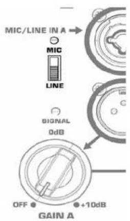
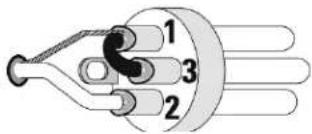
Balanced Inputs: Connect to the plug as shown.
text_image
1 2 31 = Shield (ground)
3 = Minus (-)
2 = Plus (+)
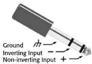
text_image
Ground Inverting Input Non-inverting InputUnbalanced Inputs: Connect to the plug as shown. If a 3 conductor (TRS) plug is used to connect an unbalanced source, Pin 3 and pin 1 must be connected with a jumper as shown.
text_image
1 2 31 = Shield (ground)
3 = Minus (-)
2 = Plus (+)
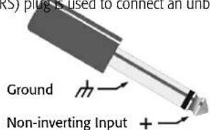
text_image
RS) plug is used to connect an unb Ground Non-inverting Input +Input Connections
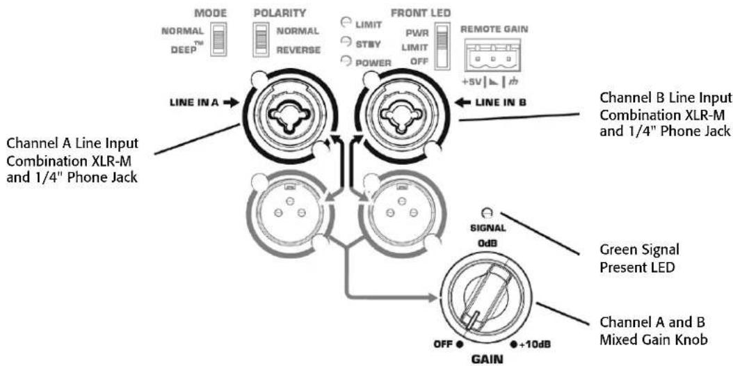
KSub
flowchart
graph TD
    A["Channel A Line Input Combination XLR-M and 1/4" Phone Jack"] --> B["MODE NORMAL DEEP™"]
    B --> C["Polarity NORMAL REVERSE"]
    C --> D["LIMIT STBY POWER"]
    D --> E["FRONT LED PWR LIMIT OFF"]
    E --> F["REMOTE GAIN +SV↓↓↑"]
    F --> G["LINE IN A"]
    G --> H["Signal 0dB"]
    H --> I["OFF"]
    I --> J["+10dB GAIN"]
    J --> K["Channel B Line Input Combination XLR-M and 1/4" Phone Jack"]
    K --> L["Green Signal Present LED"]
    L --> M["Channel A and B Mixed Gain Knob"]
The KSub is designed to accept Line Level inputs connected either by male XLR or 1/4" phone (TS or TRS) jack. If signal is connected to both Channel A and Channel B, they will be summed together. The gain of the summed signal is then controlled using the Gain knob. This affects the amount of signal sent to the amplifier and then to the loudspeaker components. The green SIGNAL LED will illuminate when signal is present, regardless of the amount of gain as set by the Gain knob. If the LED does not illuminate, the input is not receiving any signal, or the level of the signal is significantly low. Check all connections and the status of the device delivering the signal.
Output Connections
K8, K10, K12
flowchart
graph TD
    A["Channel A Line Level Direct Output"] --> B["Signal 0dB"]
    B --> C["Channel A Gain Knob"]
    C --> D["OFF +10dB"]
    D --> E["GAIN A"]
    E --> F["LINE OUT (POST GAIN - MIX)"]
    F --> G["OFF +10dB"]
    G --> H["GAIN B"]
    H --> I["Channel B Gain Knob"]
    I --> J["Signal 0dB"]
    J --> K["Channel B Line Level Direct Output"]
    K --> L["OFF +10dB"]
    L --> M["GAIN B"]
    M --> N["Post-Gain Line Output"]
ENG
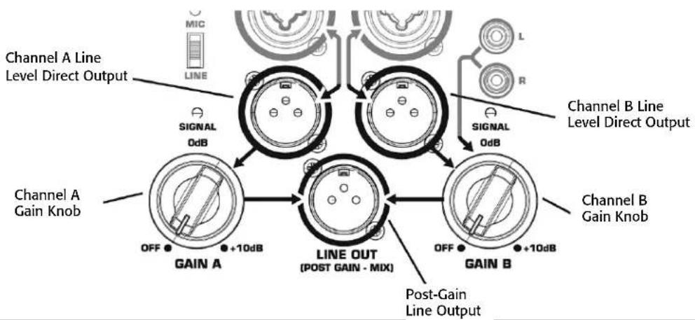
Both Channel A and Channel B have discreet direct outputs on male XLR connectors. The signal on this output is exactly equivalent to the signal from the corresponding input. The level of the output signal is not affected by the gain setting for that channel. Additionally, signal delivered on the RCA (phono) jacks is not present on the Channel B direct line level output.
The Post-Gain Line out male XLR connector is a mixed output of Channel A, Channel B and the RCA (phono) jacks. This mix is affected by gain knobs on both Channel A and Channel B and the MIC/LINE switch on Channel A, but the output level is still Line Level.

WARNING! Do not connect the POST-GAIN LINE OUTPUT of a K Series system to any INPUT of the SAME UNIT. This output is designed to send signal to OTHER K Series units or to other audio equipment. Failure to follow this warning may result in very unpleasant sounds produced at extremely high output volumes.
Output Connections
KSub
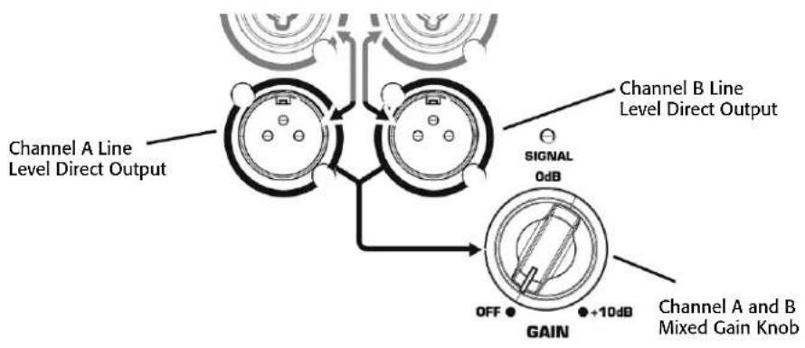
Both Channel A and Channel B have discrete direct outputs on male XLR connectors. The signal on this output is exactly equivalent to the signal from the corresponding input. The level of the output signal is not affected by the gain set on the subwoofer gain knob.
DSP Features
The K Series features advanced DSP (digital signal processing) circuitry that performs many functions. Some functions are set at the design/production level and are not user accessible. These functions include crossovers, time alignment, limiting and protection, thermal management and a number of proprietary features. QSC has designed exclusive DSP functions that greatly enhance the capabilities and performance of the K Series systems.
Proprietary DSP Functions
Excursion Limiting: In addition to signal limiting to protect the amplifier and transducers from overload, the K Series utilizes a proprietary limiter that prevents woofer over-excursion. Over-excursion occurs when a voltage presented to the woofer causes the cone to physically travel too far. This builds up excessive heat, stresses the moving parts of the woofer, produces audible artifacts and distortion and reduces the woofer's lifespan. The proprietary algorithm contained in Excursion Limiting prevents over-excursion. Voltages that will harm the woofer through over-excursion are reduced enough to prevent over-excursion without any audible compression, limiting or loss.
DEEP™: Taking advantage of the Excursion Limiter, the DEEP (Digital Extension and Excursion Processing) algorithm functions as a highly musical and non-distorting low-frequency EQ circuit. More on the DEEP function is available in the EQ section of this manual.
Intrinsic Correction™: Introduced on QSC Concert/Touring products, Intrinsic Correction is a proprietary process and set of signal processing algorithms that address correctable characteristics of transducers and waveguides. The net result is that any K Series system will present extraordinarily even and consistent energy throughout the physical listening area of the loudspeaker, resulting in a very musical, acoustically transparent system.
DSP User Functions
Low-frequency EQ
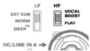
On the K8, K10 and K12, there are three low-frequency settings. From the factory, the switch is set to "NORM." This means that the loudspeaker system is producing a normal low-frequency signal through the woofer. This is the standard setting for most applications. (Figure 7)
When using one of the top boxes with a subwoofer, the switch should be moved to the "EXT SUB" position to engage the 100 Hz high-pass filter. It is also recommended that the 100 Hz high-pass filter be engaged when using the K10 or K12 as a floor monitor to prevent excessive bass build up on the stage.
For extra low-frequency extension and low-end presence when using one of the top boxes without a sub, move the switch to the "DEEP" setting. This will engage the proprietary DEEP algorithm, providing increased low-frequency extension without causing distortion or woofer over-excursion.
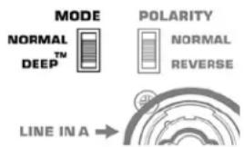
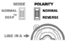
On the KSub there are two low-frequency settings. From the factory, the switch is set to "NORM." This means that the subwoofer system is producing a non-EQ'd low-frequency signal through the woofer. This is the standard setting for most applications. (Figure 8)
For extra low-frequency extension and low-end presence, move the switch to the "DEEP" setting. This will engage the proprietary DEEP algorithm, providing increased low-frequency extension without causing distortion or woofer over-excursion.
High-frequency EQ
On the K8, K10 and K12 there are two high-frequency settings. From the factory, the switch is set to "FLAT." This means that the loudspeaker system is producing a flat response through the vocal band. This is the standard setting for most applications. (Figure 9)
In voice-only reproduction, the switch can be set to the "VOCAL BOOST" setting. This will engage EQ that gives a stronger presence for vocal intelligibility and presence. It is generally not recommended to use this setting when playing full-range music through the system.

text_image
LF EXT SUB NORM DEEP™ HF VOCAL BOOST FLAT IIC/LINE IN A →- Figure 7 -
text_image
MODE NORMAL DEEP™ POLARITY NORMAL REVERSE LINE IN A →- Figure 8 -
text_image
LF EXT SUB NORM DEEP™ HF VOCAL BOOST FLAT IIC/LINE IN A →- Figure 9 -
Subwoofer Polarity
Polarity (sometimes improperly referred to as phase) refers to the voltage of an input signal and whether it is a positive or negative voltage at any given time. In most cases a positive voltage causes a woofer cone to move forward with respect to the cabinet orientation, and a negative voltage then moves the woofer cone backward. Most importantly, speakers reproducing the same signal or signals that are adjacent in frequency must have the same polarity to get the maximum output. This is most important for low frequencies. Polarity can be altered by incorrect wiring or mixer control settings. (Figure 10)
When using the KSub with K Series full range loudspeakers, NORMAL polarity will result in the best bass response IF the full range loudspeakers are sitting on or very close to the subwoofers. If the subwoofers are some distance away from the full range loudspeakers, polarity change may be of benefit. Start with all subwoofer POLARITY switches in the NORMAL position. Then, with the system at or near expected operating levels, change the polarity of each subwoofer INDIVIDUALLY. Walk around the venue and assess the overall bass response. Select the polarity that results in the best overall system bass response.
When using only one KSub and connecting a LEFT and RIGHT stereo signal, start with the polarity switch in the NORMAL position. With the system at a reasonable level, change the POLARITY switch and evaluate which polarity results in the most low-frequency output.
text_image
MODE NORMAL TM DEEP POLARITY NORMAL REVERSE LINE IN A →- Figure 10 -
ENG
Additional Features
Standby
All K Series models are equipped with an automatic standby feature to conserve energy when the systems are not in use. If no signal is present on any input of a K Series system or the gain knob is turned to off for five minutes, the power amplifier will go into standby and the green STANDBY LED will illuminate. No other LEDs will illuminate when the unit is in standby; this includes both the Rear Power LED and the Front Power LED. In this mode, the amplifier will be powered down. A small amount of voltage will continue to flow from the AC power source into the power supply of the K Series power module. This voltage will keep the power supply and DSP "awake" to reduce turn on time when the system is brought out of standby. The power up time of the amplifier is negligibly small and is shorter than the latency of the DSP, so no signal will be cut off when the K Series system is brought out of standby. A K Series loudspeaker can also be brought out of standby manually by turning the power switch off and then back on.
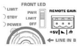
Front Power LED Functions
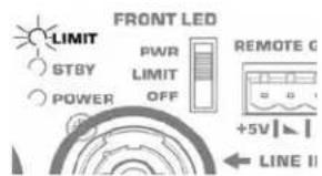
The Front Power LED may be set to any of three modes by the rear-mounted Power LED switch. (Figure 11)
- From the factory, the Power LED switch is set to the PWR position. The Front Power LED will illuminate when the power switch is in the ON position and the unit is not in Standby.
- In the "OFF" position, the Front Power LED will not illuminate. This setting is recommended in applications where the Front Power LED may be visually objectionable while the unit is operating.
- In the LIMIT setting the Front Power LED will track the LIMIT LED on the rear of the unit. When the K Series is in Limiting (meaning that one or more of the limiters is engaging to protect some part of the system) the Front Power LED will glow brighter in response to the limiting function. This allows the system operator to have awareness of the status of the limiters without needing to see the rear of the unit. For more information see the section below on the Rear LIMIT LED. When not in limiting and when the unit is not in standby, the front power LED will be illuminated dimly.
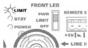
Rear LIMIT LED
The red LIMIT LED can indicate that limiting has taken place to protect and avoid damage to the amplifier or loudspeaker. (Figure 12) If the signal level at any frequency is too high, the DSP will limit the signal to prevent damage and the red LIMIT LED will illuminate. If the amplifier is too hot because the SPL is too high or the environment is too hot, the red LIMIT LED will be illuminated. If the red LIMIT LED is on when both Gain controls are at minimum, your K Series loudspeaker requires service by qualified personnel.
text_image
FRONT LED LIMIT PWR REMOTE GAIN STBY LIMIT OFF +5V | ↓ | 电 POWER LINE IN B- Figure 11 -
text_image
FRONT LED LIMIT PWR REMOTE G STBY LIMIT POWER OFF +5V LINE II- Figure 12 -
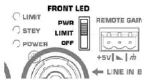
Remote Gain Attenuator
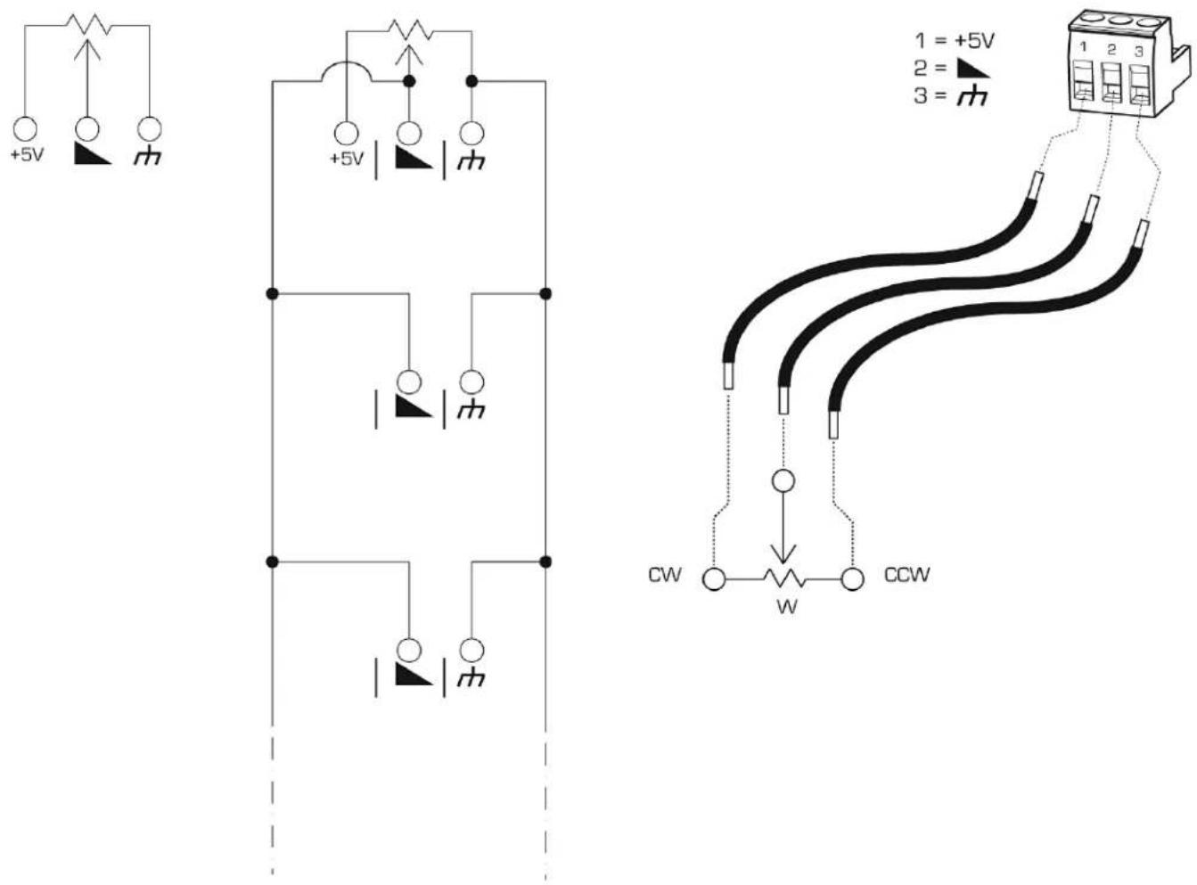
A 3 pin "Euro" connector has been provided to adjust the volume of the K Series loudspeaker or put the system into standby. (Figure 13) By varying the voltage on the ▲ pin between +5V (provided on +5V pin) and ground (m pin), the volume can be linearly controlled. The voltage on the ▲ pin can be created by using a potentiometer or provided from an external source. Many K Series systems can be controlled from a single potentiometer by connecting the ▲ pins of multiple K Series speakers together.
A relay or manual connection can be made between the ▶ pin and the pin to put the K Series system into standby mode after 5 minutes.
text_image
FRONT LED LIMIT STBY POWER PWR LIMIT OFF REMOTE GAIN +5V | ▲ | m ← LINE IN B- Figure 13 -

WARNING: Do not put more than +5V or less than ground on the ▶ pin or else damage may occur. Do not connect the ▶ pin directly to the +5V pin.
Schematics of Proper Wiring for Gain Attenuator
When using a single potentiometer for one loudspeaker. (Figure 14)
When using a single potentiometer for multiple loudspeaker. (Figure 15)
Wiring to the 3 pin "Euro" connector. (Figure 16)
- Figure 16 -- Figure 14 -- Figure 15 -
Applications
Input Hookup
flowchart
graph LR
    ENG --> A["ENGLISH BOARD"]
    ENG --> B["LOGIC REGulator"]
    ENG --> C["AC/DC Receiver"]
    A --> D["OSC"]
    B --> D
    C --> D
    D --> E["Digital Display"]
    D --> F["Radio Station"]
Output Hookup
natural_image
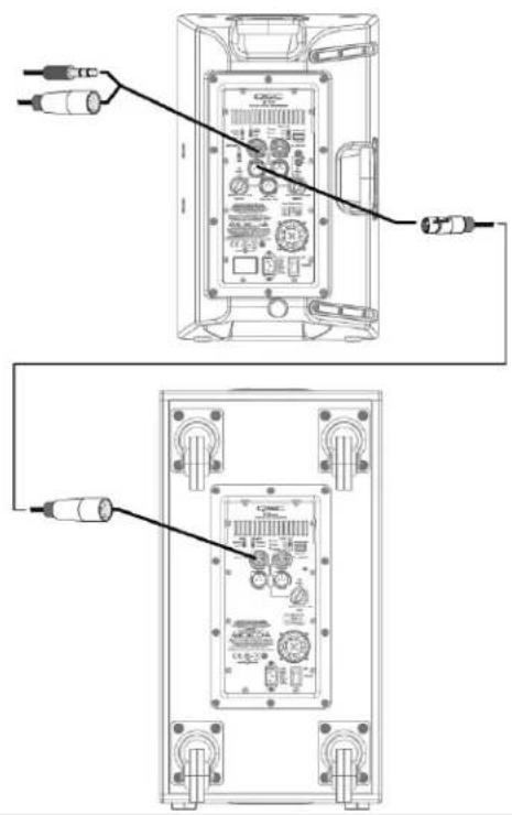
Diagram showing two views of a device with connected cables and connectors (no text or symbols)Output Hookup

text_image
Technical diagram showing two views of an electronic device with labeled ports and connectors, likely from an electronics or audio testing setup.
text_image
Diagram showing connections between audio equipment via a device, including a guitar, CD, and multiple audio monitors with labeled OR connectors.Common Standalone Small System (Mono)
text_image
Diagram showing connections between audio equipment and a CD-ROM monitor, with labeled components and wiring.ENG
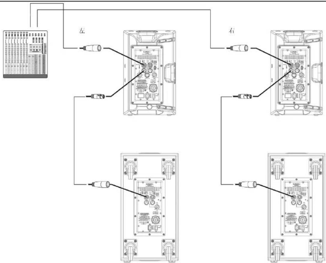
Common Stereo System

flowchart
graph TD
    A["Device"] --> B["Left Right"]
    B --> C1["Component 1"]
    B --> C2["Component 2"]
    B --> C3["Component 3"]
    B --> C4["Component 4"]
    C1 --> D1["External Circuit"]
    C2 --> D2["External Circuit"]
    C3 --> D3["External Circuit"]
    C4 --> D4["External Circuit"]
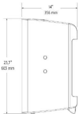
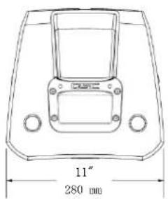
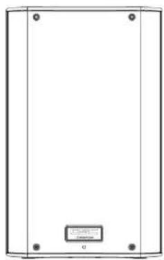
Dimensions
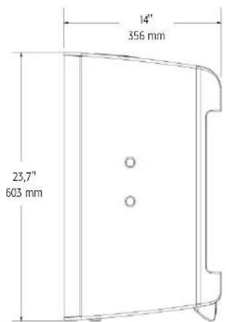
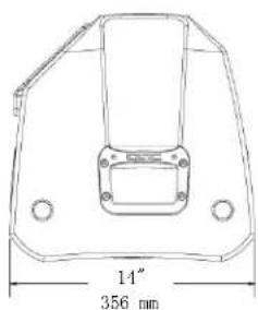
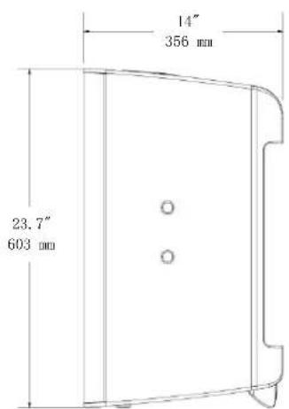
K12

text_image
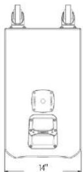
14" 356 mmTop

natural_image
Simple line drawing of a rectangular frame with four corner dots and a small labeled box at the bottom (no text or symbols)Front Side
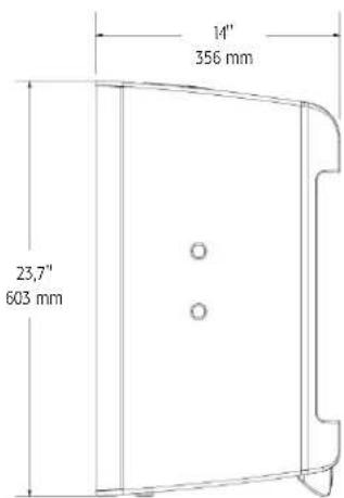
text_image
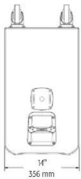
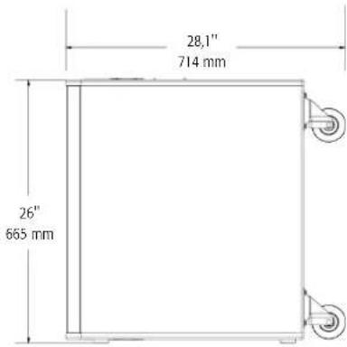
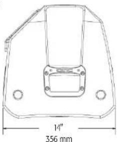
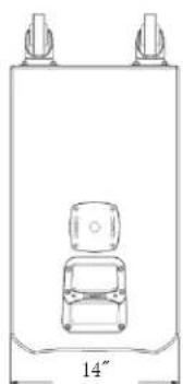
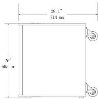
14" 356 mm 23.7" 603 mmKSub
natural_image
Simple line drawing of a vehicle inside a container with two top tabs and a side view labeled '14'' (no text or symbols on the diagram itself)356 mm
Top
natural_image
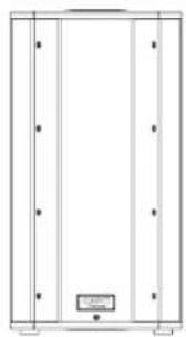
Pure architectural or mechanical diagram showing vertical supports and a central component (no text or symbols)Front Side

text_image
28.1" 714 mm 26" 665 mmSpecifications
K8 K10 K12 KSub
natural_image
Technical line drawing of a speaker or audio device with concentric circles and mounting brackets (no text or symbols)
natural_image
Technical line drawing of a speaker with two concentric circles and mounting brackets (no text or symbols)
natural_image
Pure architectural or mechanical diagram with vertical panels and a small labeled component (no text or symbols)Configuration Trapezoidal 2-way Multipurpose 2-way Multipurpose 2-way 4th Order Bandpass
| Transducers | ||||
| Low-frequency | 8" cone transducer | 10" cone transducer | 12" cone transducer | 2 x 12" cone transducers |
| High-frequency | 1.75" diaphragm compression driver | 1.75" diaphragm compression driver | 1.75" diaphragm compression driver | |
Frequency Response (-6 dB) 66 Hz - 18 kHz 60 Hz - 18 kHz 52 Hz - 18 kHz 48 Hz - 134 Hz
ENG
Frequency Range (-10 dB) 61 Hz - 20 kHz 56 Hz - 20 kHz 48 Hz - 20 kHz 44 Hz - 148 Hz
| Nominal Coverage (-6 dB) 105° conical 90° conical 75° conical | ||||
| Maximum SPL (1 meter) | 127 dB peak | 129 dB peak | 131 dB peak | 130 dB peak |
| Amplifiers | ||||
| Power Output | 1000 W Class D | |||
| Input Impedance (Ω) | XLR/14": 40k balanced/20k unbalanced • XLR/14" MIC mode: 2260 balanced • RCA: 10k | |||
| Controls | Power • Gain A • Gain B • Mic/Line • LF Mode (Ext Sub/Norm/DEEPTM) • HF Mode (Flat/Vocal Boost) Front LED (On/Off/Limit) | Power • Gain • LF Mode (Normal/ DEEPTM) • Polarity (Normal/Reverse) • Front LED (On/Off/Limit) | ||
| Indicators | Power • Signal A • Signal B • Standby • Limit • Mic | Power • Signal • Standby • Limit | ||
| Connectors | Balanced female XLR/14" line/mic level input • Balanced female XLR / 1/4" line level input • Dual Balanced male XLR full range line level out • Balanced male XLR "mix" out • Stereo RCA line level input • Remote gain control • Locking IEC power connector | Dual balanced female XLR/14" line level input • Dual Balanced male XLR full range line level out • Remote gain control • Locking IEC power connector | ||
| Cooling | On demand, 50 mm variable speed fan | |||
| Amplifier Protection | Thermal limiting • Output overcurrent • Overtemperature muting • GuardRailTM | |||
| Transducer Protection | Thermal limiting • Excursion limiting | |||
| AC Power Input | Universal power supply 100 - 240 VAC, 50 - 60 Hz | |||
| AC Power Consumption 1/8 Power | 100 VAC, 2.3 A • 120 VAC, 2.01 A • 230 VAC, 1.13 A | |||
| Enclosure | Impact resistant ABS | Painted birch plywood | ||
| Finish | Black Paint | Black textured paint | ||
| Grille | Black powder coated 18 gauge steel | |||
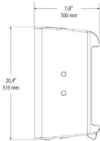
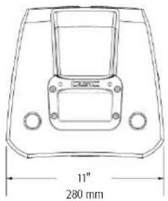
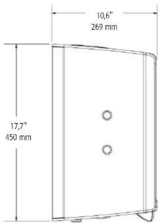
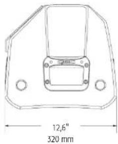
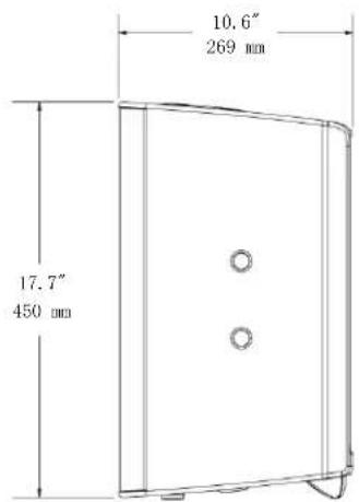
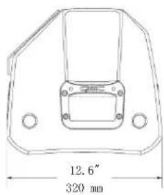
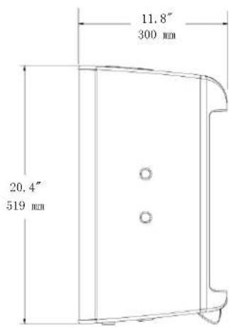
| Dimensions (HWD) | 17.7" x 11" x 10.6" | 20.4" x 12.6" x 11.8" | 23.7" x 14" x 14" | 26" x 14" x 28.1" (including casters) |
| 450 mm x 280 mm x 269 mm | 519 mm x 320 mm x 300 mm | 603 mm x 356 mm x 356 mm | 665 mm x 356 mm x 714 mm | |
| Weight (Net) | 27 lb (12.2 kg) | 32 lb (14.5 kg) | 41 lb (18.6 kg) | 74 lb (33.6 kg) |
| Available Accessories | K8 TOTE • K8 YOKE • K SERIES M10 KIT | K10 TOTE • K10 YOKE • K SERIES M10 KIT | K12 TOTE • K12 YOKE • K SERIES M10 KIT | KSub COVER |
Specifications subject to change without notice.
QSC™
Mailing Address:
QSC Audio Products, LLC
1675 MacArthur Boulevard
Costa Mesa, CA 92626-1468 USA
Telephone Numbers:
Main Number: 714-754-6175
Sales & Marketing: 714-957-7100 or toll free (USA only) 800-854-4079
Customer Service: 714-957-7150 or toll free (USA only) 800-772-2834
Facsimile Numbers:
Sales & Marketing FAX: 714-754-6174
Customer Service FAX: 714-754-6173
World Wide Web:
qscaudio.com
E-mail:
info@qscaudio.com
service@qscaudio.com
natural_image
Technical line drawing of a speaker or audio device casing with no visible text or symbols
natural_image
Technical line drawing of a speaker or audio device casing with concentric circles and mounting brackets (no text or symbols)
natural_image
Technical line drawing of a speaker with two concentric circles and mounting brackets (no text or symbols)
natural_image
Pure technical line drawing of a cabinet or enclosure with no text, numbers, or symbolstext_image
Technical diagram of a device with numbered components, likely an electronic device or control panel.K10
text_image
Technical diagram of a device's internal components with numbered labels for identification.K12
text_image
Technical diagram of a device with numbered components for identification and assembly reference.KSub
text_image
Technical diagram of an electrical enclosure with labeled components and exploded viewsAplicaciones
natural_image
Technical line drawing of a mechanical housing or enclosure with mounting holes and internal components (no text or symbols)- Figura 1 -
natural_image
Line drawing of a simple stand with three legs and a central panel (no text or symbols)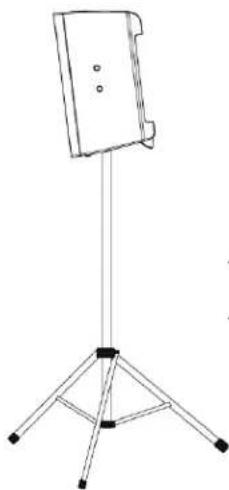
natural_image
Line drawing of a tripod-mounted stand with a flat top (no text or symbols)- Figura 2 -
natural_image
Technical line drawings of two mechanical components with mounting holes and internal compartments (no text or symbols)- Figura 3 -
natural_image
Pure electrical circuit lines without any symbols- Figura 4 -
Instalación

text_image
SPA K8 K10 K12natural_image
Diagram of a plug with two pins and directional arrows indicating connection (no text or symbols)
text_image
MODE NORMAL DEEP™ POLARITY NORMAL REVERSE LINE IN A →- Figura 8 -

text_image
LF EXT SUB NORM DEEP™ HF VOCAL BOOST FLAT IIC/LINE IN A →- Figura 9 -
natural_image
Diagram showing two identical electronic device setups connected by wires, no text or symbols presentConexión de salida

text_image
Technical diagram showing two views of a device rear panel with labeled connectors and ports, likely for assembly or testing purposes.
text_image
Diagram showing audio connection wiring between a guitar and two audio monitors, with labels for each device.text_image
Diagram showing connections between audio equipment and a CD-ROM monitor, with labeled components and wiring.SPA
natural_image
Simple line drawing of a rectangular frame with corner markers and a small labeled box at the bottom (no text or symbols)Frente Lado
text_image
14" 356 mm 23,7" 603 mmKSub
natural_image
Technical line drawing of a vehicle inside a rectangular frame with a 14-inch top and 356 mm base (no text or symbols)Parte superior
natural_image
Pure architectural or mechanical diagram showing vertical supports and a central component (no text or symbols)Frente Lado
text_image
28,1" 714 mm 26" 665 mmEspecificaciones


natural_image
Technical line drawing of a speaker or audio component with concentric circles and mounting brackets (no text or symbols)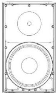
natural_image
Technical line drawing of a speaker with two concentric circles and mounting brackets (no text or symbols)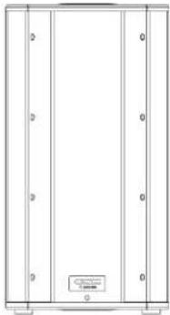
natural_image
Pure architectural or mechanical diagram with vertical panels and a small labeled component (no text or symbols)K8 K10 K12 KSub
QSC Audio Products, LLC
1675 MacArthur Boulevard
service@qscaudio.com
natural_image
Technical line drawing of a speaker or audio device casing with no visible text or symbols
natural_image
Technical line drawing of a speaker or audio device with concentric circles and mounting brackets (no text or symbols)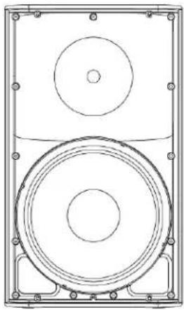
natural_image
Technical line drawing of a speaker with two concentric circles and mounting brackets (no text or symbols)
natural_image
Pure architectural or mechanical diagram with vertical panels and a small labeled component (no text or symbols)PRÉCAUTIONS IMPORTANTES ET EXPLICATION DES SYMBOLES

AVERTISSEMENT !

ATTENTION : POUR RÉDUIRE LES RISQUE D'ÉLECTROCUTION, NE PAS RETIRER LE CAPOT DE L'AMPLIFICATEUR. AUCUNE PIÈCE RÉPARABLE PAR L'UTILISATEUR À L'INTÉRIEUR. CONFIER TOUTE RÉPARATION À UN PERSONNEL QUALIFIÉ.

text_image
Technical diagram of a device with numbered components, likely an electronic or mechanical assembly.K10
text_image
Technical diagram of a device's internal components with numbered labels for identification.K12
text_image
Technical diagram of a device with numbered components, likely an electronic or mechanical assembly.KSub
text_image
Technical diagram of an electrical enclosure with labeled components and exploded viewsApplications
natural_image
Technical line drawing of a mechanical housing or enclosure with mounting holes and internal components (no text or symbols)- Figure 1 -
natural_image
Simple line drawing of a tripod-mounted device with a rectangular panel on top (no text or symbols)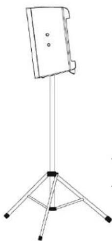
natural_image
Line drawing of a tripod-mounted stand with a flat top and three legs (no text or symbols)- Figure 2 -

natural_image
Technical line drawings of two mechanical components with mounting holes and internal compartments (no text or symbols)- Figure 3 -

natural_image
Pure electrical circuit lines without any symbols- Figure 4 -
Installation

text_image
K12 24" (612 mm) K SERIES POLE KSubtext_image
FRE K8 K10 K12natural_image
Diagram of a plug with internal components and directional arrows indicating connection (no text or symbols)text_image
1 = Terre 3 = Moins (-) 2 = Plus (+)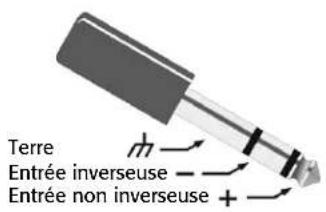
text_image
1 = Terre 3 = Moins (-) 2 = Plus (+)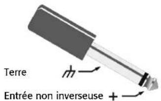
text_image
Terre Entrée non inverseuse +text_image
MODE NORMAL DEEP™ POLARITY NORMAL REVERSE LINE IN A →- Figure 8 -

text_image
LF EXT SUB NORM DEEP™ HF VOCAL BOOST FLAT IIC/LINE IN A →- Figure 9 -
natural_image
Diagram showing two identical electronic device setups connected by cable, with no visible text or symbols.text_image
Technical diagram showing two views of an electronic device with labeled connectors and ports, likely from an electronics or audio testing setup.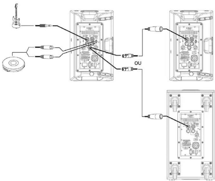
text_image
Diagram showing connections between audio equipment via USB cable, with labels for guitar, CD, and output (OU)text_image
Diagram showing connections between audio equipment and a CD-ROM monitor, with labeled components like LME, audio jack, and camera.FRE
text_image
11" 280 mm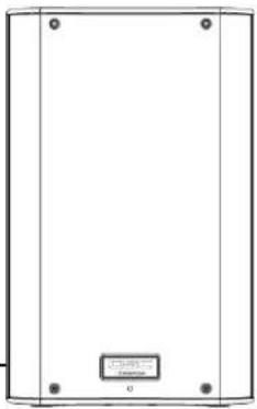
natural_image
Simple line drawing of a rectangular frame with four corner holes and a small labeled box at the bottom (no text or symbols)Avant Côté
Haut
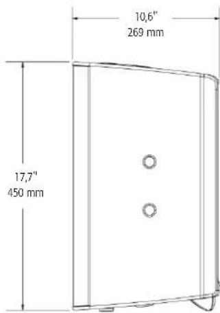
text_image
10,6" 269 mm 17,7" 450 mmK10
text_image
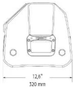
12,6" 320 mm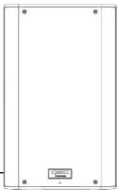
natural_image
Empty rectangular frame with four corner holes and a small labeled box at the bottom (no text or symbols on the main body)Avant Côté
Haut
text_image
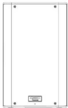
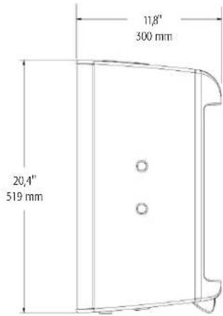
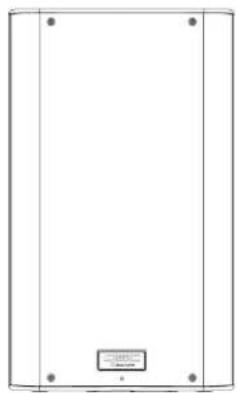
11,8" 300 mm 20,4" x 519 mmK12
text_image
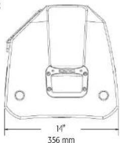
14" 356 mm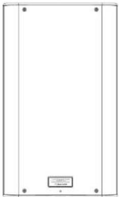
natural_image
Simple line drawing of a rectangular frame with four corner dots and a small labeled box at the bottom (no text or symbols)Avant Côté
Haut
text_image
14" 356 mm 23,7" 603 mmKSub

natural_image
Simple line drawing of a vehicle inside a container with two top tabs and a 14-inch base (no text or symbols)356 mm

natural_image
Pure architectural or mechanical diagram showing vertical supports and a central component (no text or symbols)Avant Côté
Haut

text_image
28,1" 714 mm 26" 665 mmnatural_image
Technical line drawing of a speaker or audio component with concentric circles and mounting brackets (no text or symbols)
natural_image
Technical line drawing of a speaker with two concentric circles and mounting brackets (no text or symbols)
natural_image
Pure architectural or mechanical diagram with vertical panels and a small labeled component (no text or symbols)K8 K10 K12 KSub
QSC Audio Products, LLC
1675 MacArthur Boulevard
service@qscaudio.com
natural_image
Technical line drawing of a speaker or audio device casing with no visible text or symbols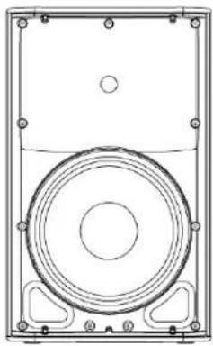
natural_image
Technical line drawing of a speaker or audio device with concentric circles and mounting brackets (no text or symbols)
natural_image
Technical line drawing of a speaker with two concentric circles and mounting brackets (no text or symbols)
natural_image
Pure architectural or mechanical diagram showing vertical panels and a central label (no text or symbols)text_image
Technical diagram of a device with numbered components, likely an electronic or mechanical assembly.GER
K10
text_image
Technical diagram of a device's internal components with numbered labels for identification.K12
text_image
Technical diagram of a device with numbered components for identification and assembly reference.KSub
text_image
Technical diagram of an electrical enclosure with labeled components and wiring connectionsAnwendungen
natural_image
Technical line drawing of a mechanical housing or enclosure with mounting holes and internal components (no text or symbols)- Abbildung 1 -
natural_image
Simple line drawing of a tripod-mounted device with a rectangular panel on top (no text or symbols)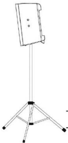
natural_image
Simple line drawing of a tripod-mounted stand with a flat top (no text or symbols)- Abbildung 2 -
natural_image
Technical line drawings of two mechanical components with mounting holes and internal compartments (no text or symbols)- Abbildung 3 -

natural_image
Pure electrical circuit lines without any symbols- Abbildung 4 -
Installation

text_image
GER K8 K10 K12natural_image
Diagram of a plug with two pins and a connector, showing internal wiring (no text or symbols)
flowchart
graph TD
    A["GER"] --> B["Audio Input"]
    B --> C["Adder"]
    C --> D["Adder with MRC"]
    D --> E["Adder with LINE"]
    E --> F["Adder with Oscillator"]
    F --> G["Adder with CD/DVD"]
    G --> H["Adder with Monitor"]
natural_image
Diagram showing two identical electronic device setups connected by wires, no text or symbols presenttext_image
Technical diagram showing two views of an electronic device with labeled ports and connectors, likely for assembly or maintenance instructions.
text_image
Diagram showing connections between audio equipment and ODER devices, with labels for guitar, CD, and audio output ports.text_image
Diagram showing connections between audio equipment and a CD-ROM monitor, with labeled components and wiring.GER
Stereosystem
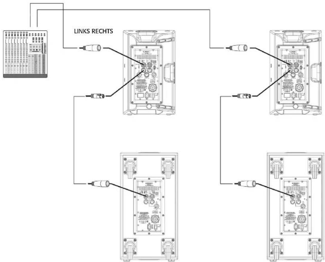
flowchart
graph TD
    A["Instrument"] --> B["Link Rechts"]
    B --> C["Device 1"]
    B --> D["Device 2"]
    B --> E["Device 3"]
    B --> F["Device 4"]
    C --> G["Output"]
    D --> H["Output"]
    E --> I["Output"]
    F --> J["Output"]
Abmessungen
K8
text_image
11" 280 mmOben

natural_image
Simple line drawing of a rectangular enclosure with four corner holes and a small labeled box at the bottom (no text or symbols on the main structure)Frontseite Seite
text_image
10,6" 269 mm 17,7" 450 mmK10
text_image
12,6" 320 mmOben
natural_image
Blank rectangular panel with four corner holes and a small labeled box at the bottom (no text or symbols on the panel itself)Frontseite Seite
text_image
11,8" 300 mm 20,4" x 519 mmK12
text_image
14" 356 mmOben
natural_image
Simple line drawing of a rectangular frame with corner markers and a small labeled box at the bottom (no text or symbols)Frontseite Seite
text_image
14" 356 mm 23.7" 603 mmKSub
natural_image
Simple line drawing of a vehicle inside a container with two top tabs and a 14-inch base (no text or symbols)356 mm
Oben
natural_image
Pure architectural or mechanical diagram showing vertical panels and a small labeled component (no text or symbols)Frontseite Seite

text_image
28,1" 714 mm 26" 665 mmTechnische Daten

natural_image
Technical line drawing of a speaker or audio component with concentric circles and mounting brackets (no text or symbols)
natural_image
Technical line drawing of a speaker with two concentric circles and mounting brackets (no text or symbols)
natural_image
Pure architectural or mechanical diagram with vertical panels and a small labeled component (no text or symbols)K8 K10 K12 KSub
QSC Audio Products, LLC
1675 MacArthur Boulevard
Costa Mesa, CA 92626-1468 USA
Telefonnummern:
service@qscaudio.com
K 系列
用户手册
natural_image
Technical line drawing of a speaker or audio device casing with no visible text or symbols
natural_image
Technical line drawing of a speaker or audio device casing with concentric circles and mounting brackets (no text or symbols)
natural_image
Technical line drawing of a speaker with two concentric circles and mounting brackets (no text or symbols)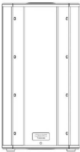
natural_image
Pure technical line drawing of a cabinet or enclosure with no text, numbers, or symbols重要的安全注意事项和符号说明

警告!

© Copyright 2009, QSC Audio Products, LLC.
美国和其他国家待批专利。
text_image
Technical diagram of a device rear panel with numbered components for identificationCHI
K10
text_image
Technical diagram of a device's internal components with numbered parts for identificationK12
text_image
Technical diagram of a device's internal components with numbered parts for identificationKSub
text_image
Technical diagram of an electrical enclosure with labeled components and exploded views应用
natural_image
Technical line drawing of a mechanical housing or enclosure with mounting holes and internal components (no text or symbols)- 图 1 -
natural_image
Line drawing of a simple stand with three legs and a central panel (no text or symbols)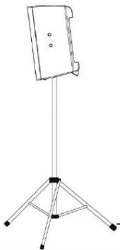
natural_image
Line drawing of a tripod-mounted stand with a flat top and three legs (no text or symbols)- 图 2 -
natural_image
Technical line drawing of a rectangular electronic enclosure or housing with mounting flanges and internal components (no text or symbols)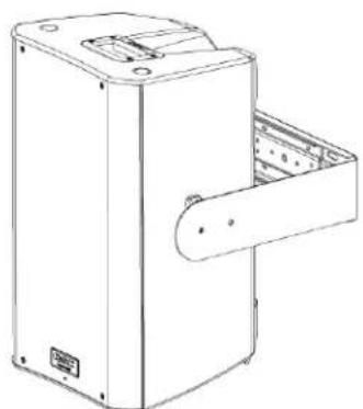
natural_image
Technical line drawing of a mechanical device with a handle and internal compartments (no text or symbols)- 图 3 -
natural_image
Pure electrical circuit lines without any symbols- 图 4 -
安装
text_image
CHI K8 K10 K12安装情况下的冷却
natural_image
Diagram of a plug with two pins and a separate housing, showing internal components and directional arrows (no text or labels)text_image
MODE NORMAL DEEP™ POLARITY NORMAL REVERSE LINE IN A →- 图 8 -

text_image
LF EXT SUB NORM DEEP™ HF VOCAL BOOST FLAT IIC/LINE IN A →- 图 9 -
重低音扬声器的极性
text_image
MODE NORMAL DEEP™ POLARITY NORMAL REVERSE LINE IN A →- 图 10 -

text_image
FRONT LED LIMIT PWR REMOTE GAIN STEV LIMIT POWER OFF +5V LINE IN B- 图 11 -
text_image
FRONT LED LIMIT PWR REMOTE G STBY LIMIT OFF POWER +5V LINE II- 图 12 -
远程增益衰减器
text_image
1 = +5V 2 = ▲ 3 = m CW ○─W ○○ CCW应用
输入端接线图
flowchart
graph TD
    A["CHI"] --> B["Radio"]
    A --> C["Audio System"]
    B --> D["Audio Receiver"]
    C --> E["Audio System"]
    D --> F["Microcontroller"]
    E --> G["Microcontroller"]
    F --> H["Line"]
    G --> H
    H --> I["Osc"]
    I --> J["CD"]
    J --> K["Digital Display"]
    style A fill:#f9f,stroke:#333
    style K fill:#ccf,stroke:#333
输出端接线图

natural_image
Diagram showing two identical electronic device setups connected by wires, no text or symbols present输出端接线图
text_image
Technical diagram showing cable connections to an audio equipment panel with labeled components and wiring paths
text_image
Diagram showing connections between audio equipment and a device, with labels for guitar, CD, and audio ports.一般单机小系统(单声道)

text_image
Diagram showing connections between audio equipment and a CD-ROM monitor, with labeled components like LME, audio jack, and camera.一般立体声系统
CHI
flowchart
graph TD
    A["左"] --> B["电缆线1"]
    A --> C["电缆线2"]
    A --> D["电缆线3"]
    E["右"] --> F["电缆线4"]
    E --> G["电缆线5"]
    E --> H["电缆线6"]
尺寸
K8
text_image
11" 280 mm顶部
natural_image
Simple line drawing of a rectangular enclosure with four corner holes and a small labeled box at the bottom (no text or symbols on the main body)正面 侧面
text_image
10.6" 269 mm 17.7" 450 mmK10
text_image
12.6" 320 mm顶部
natural_image
Empty rectangular panel with four corner holes and a small labeled box at the bottom (no text or symbols on the panel itself)正面
text_image
11.8" 300 mm 20.4" 519 mm侧面
K12
text_image
14" 356 mm顶部

natural_image
Simple line drawing of a rectangular frame with corner markers and a small labeled box at the bottom (no text or symbols)正面侧面
text_image
14" 356 mm 23.7" 603 mmKSub
natural_image
Simple line drawing of a vehicle inside a container with a 14-inch angle label (no text or symbols beyond the measurement)356 mm
顶部

natural_image
Pure architectural or mechanical diagram showing vertical supports and a central component (no text or symbols)正面侧面
text_image
28.1" 714 mm 26" 665 mm规格

K8 K10 K12 KSub

natural_image
Technical line drawing of a speaker or audio component with concentric circles and mounting brackets (no text or symbols)
natural_image
Technical line drawing of a speaker with two concentric circles and mounting brackets (no text or symbols)
natural_image
Pure architectural or mechanical diagram with vertical panels and a small labeled component (no text or symbols)QSC Audio Products, LLC
1675 MacArthur Boulevard
Costa Mesa, CA 92626-1468 USA
电话:
主要号码:714-754-6175
service@qscaudio.com