
CDVS33 - Audio-video selector PIONEER - Free user manual and instructions
Find the device manual for free CDVS33 PIONEER in PDF.
| Product Type | Vehicle audio-video selector |
| Brand | PIONEER |
| Model | CDVS33 |
| Power Supply | 14.4 V DC (10.8 - 15.1 V allowable) |
| Max. Current Consumption | 0.4 A |
| Main Unit Dimensions | 160 (W) × 28 (H) × 120 (D) mm |
| Main Unit Weight | 0.53 kg |
| Control Unit Dimensions | 120 (W) × 60 (H) × 32 (D) mm |
| Control Unit Weight | 0.32 kg |
| Audio Output Level | 1 Vp-p / 75 Ω |
| AV Inputs | 3 audio/video inputs (RCA jacks) |
| AV Outputs | 3 audio/video outputs (RCA jacks) |
| Headphone Jacks | 2 headphone outputs (PHONES A and B) with independent volume control |
| Source Selector | 3 buttons to switch between sources (1-3) |
| Power Indicator | LED (lights up when device is on) |
| Installation | Control unit mountable with L-brackets or Velcro tape |
| Usage | Rear seat audio-video selector, switching display between audio and video |
| Precautions | Do not use with a screen visible to the driver; use only in vehicles with 12V negative ground battery |
| Maintenance | Keep away from moisture, do not expose to heat |
| Safety | Connect the device to a display not visible to the driver; comply with local laws |
| Repairability | Replaceable fuse (value indicated on fuse holder); use only supplied parts |
Frequently Asked Questions - CDVS33 PIONEER
User questions about CDVS33 PIONEER
0 question about this device. Answer the ones you know or ask your own.
Ask a new question about this device
Download the instructions for your Audio-video selector in PDF format for free! Find your manual CDVS33 - PIONEER and take your electronic device back in hand. On this page are published all the documents necessary for the use of your device. CDVS33 by PIONEER.
USER MANUAL CDVS33 PIONEER
This product conforms to new cord colors.
Before Using this Product 2
About this Product 2
Precaution 2
Connecting the Units 3
Connecting the Power Cord and Controller Unit 4
Connecting the System (1) 5
Connecting the System (2) 7
Connecting the Audio/Video equipment. 9
Installation 10
Installing Hide-away Unit 10
Installing Controller Unit 11
Part Names And Applications 14
Controller Unit 14
Hide-away Unit 15
Specifications 16
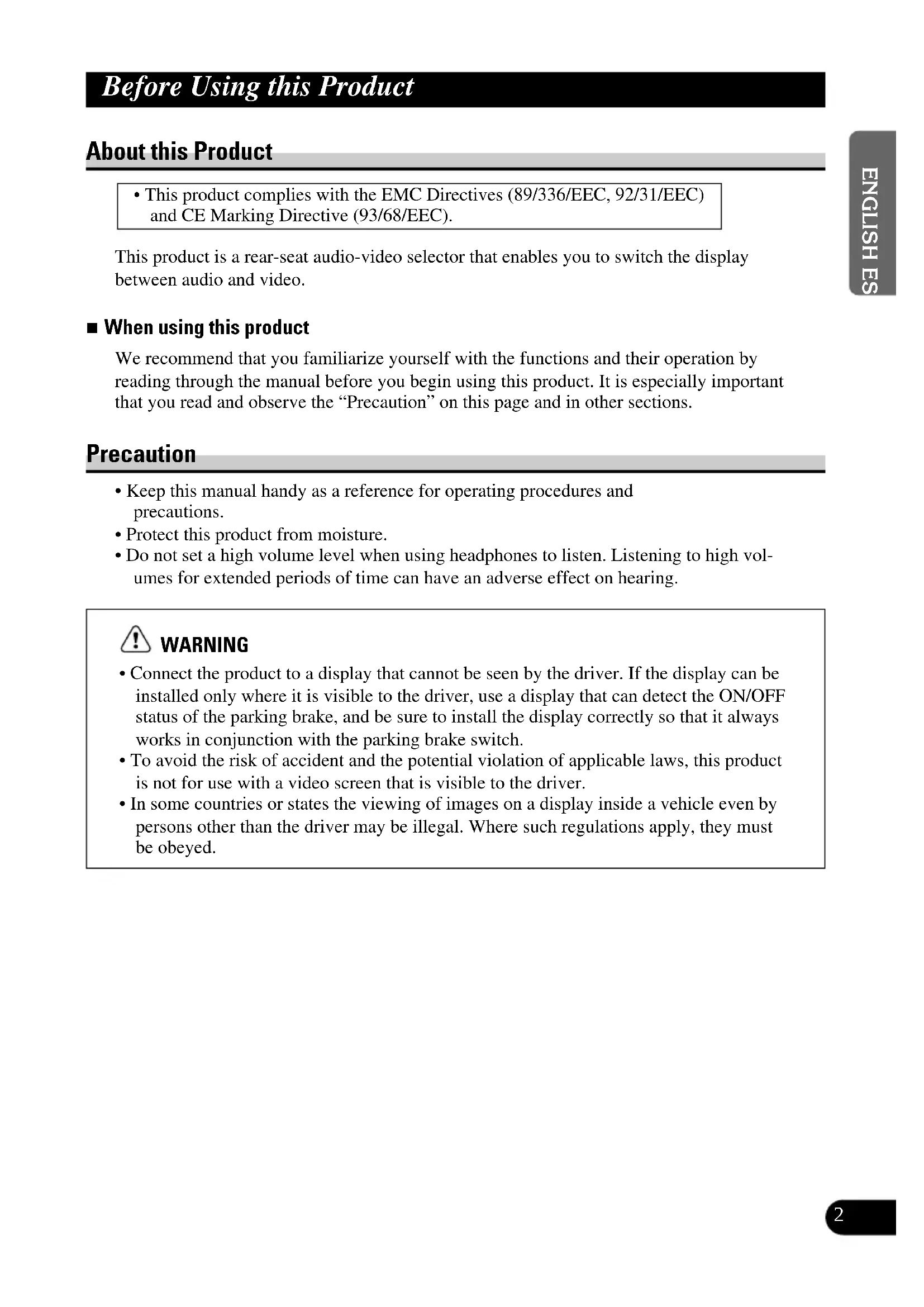
About this Product
- This product complies with the EMC Directives (89/336/EEC, 92/31/EEC) and CE Marking Directive (93/68/EEC).
This product is a rear-seat audio-video selector that enables you to switch the display between audio and video.
When using this product
We recommend that you familiarize yourself with the functions and their operation by reading through the manual before you begin using this product. It is especially important that you read and observe the "Precaution" on this page and in other sections.
Precaution
- Keep this manual handy as a reference for operating procedures and precautions.
- Protect this product from moisture.
- Do not set a high volume level when using headphones to listen. Listening to high volumes for extended periods of time can have an adverse effect on hearing.

WARNING
- Connect the product to a display that cannot be seen by the driver. If the display can be installed only where it is visible to the driver, use a display that can detect the ON/OFF status of the parking brake, and be sure to install the display correctly so that it always works in conjunction with the parking brake switch.
- To avoid the risk of accident and the potential violation of applicable laws, this product is not for use with a video screen that is visible to the driver.
- In some countries or states the viewing of images on a display inside a vehicle even by persons other than the driver may be illegal. Where such regulations apply, they must be obeyed.
Note:
- This product is for vehicles with a 12-volt battery and negative grounding. Before installing it in a recreational vehicle, truck, or bus, check the battery voltage.
- To avoid shorts in the electrical system, be sure to disconnect the battery cable before beginning installation.
- After completing installation and wiring, double check that there are no mistakes. Re-install any parts removed from the car during installation, then connect the battery negative terminal.
- Refer to the owner's manual for details on connecting the various cords of the power amp and other units, then make connections correctly.
- Secure the wiring with cable clamps or adhesive tape. To protect the wiring, wrap adhesive tape around them where they lie against metal parts.
- Route and secure all wiring so it cannot touch any moving parts, such as the gear shift, handbrake and seat rails. Do not route wiring in places that get hot, such as near the heater outlet. If the insulation of the wiring melts or gets torn, there is a danger of the wiring short-circuiting to the vehicle body.
- Do not shorten any leads. If you do, the protection circuit may fail to work when it should.
- Never feed power to other equipment by cutting the insulation of the power supply lead of the unit and tapping into the lead. The current capacity of the lead will be exceeded, causing overheating.
- When replacing a fuse, be sure to use only a fuse of the rating prescribed on the fuse holder.
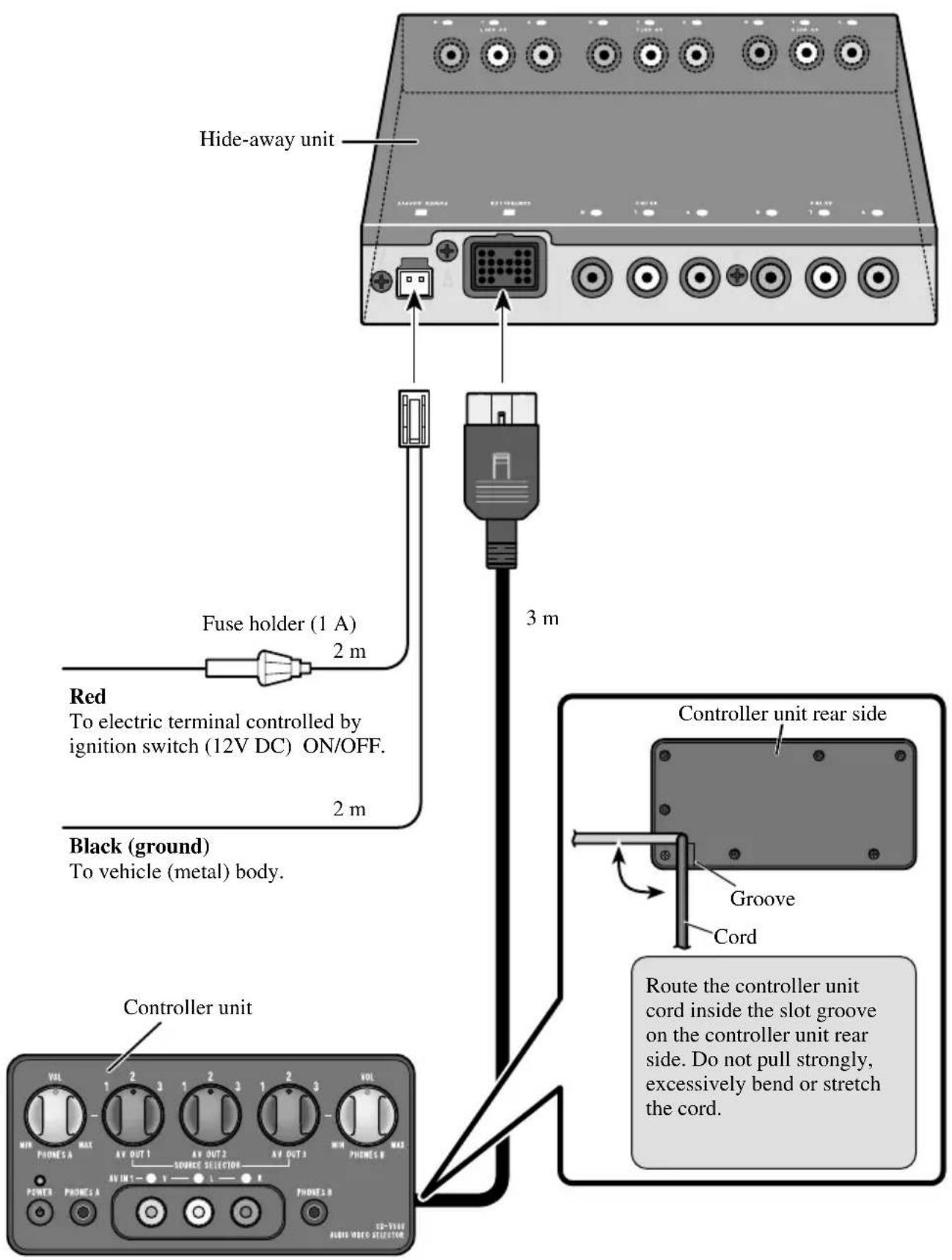
- Always grip the Controller unit when connecting an RCA pin plug.
Connecting the Power Cord and Controller Unit
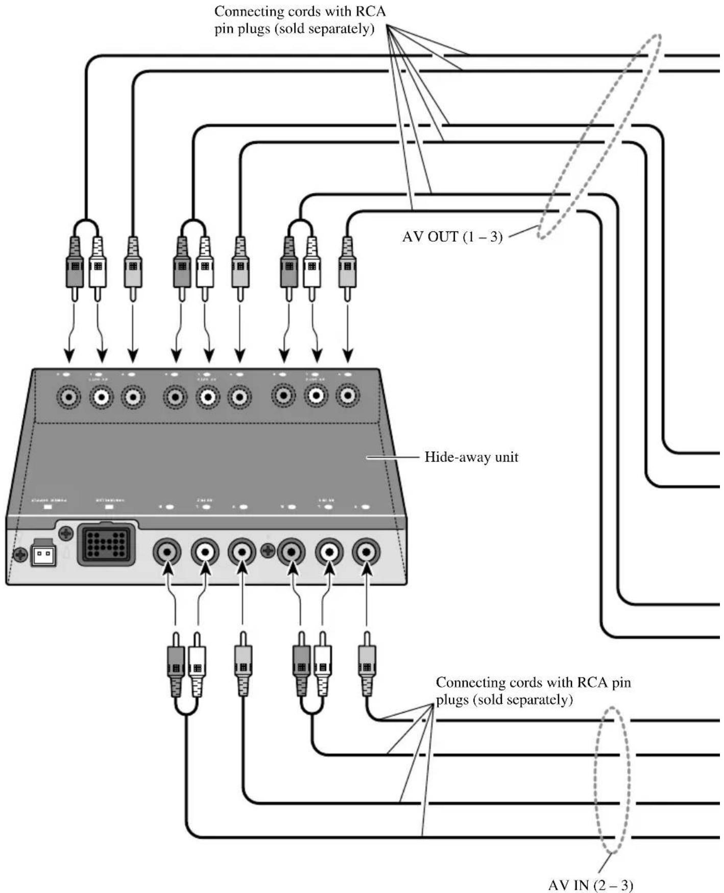
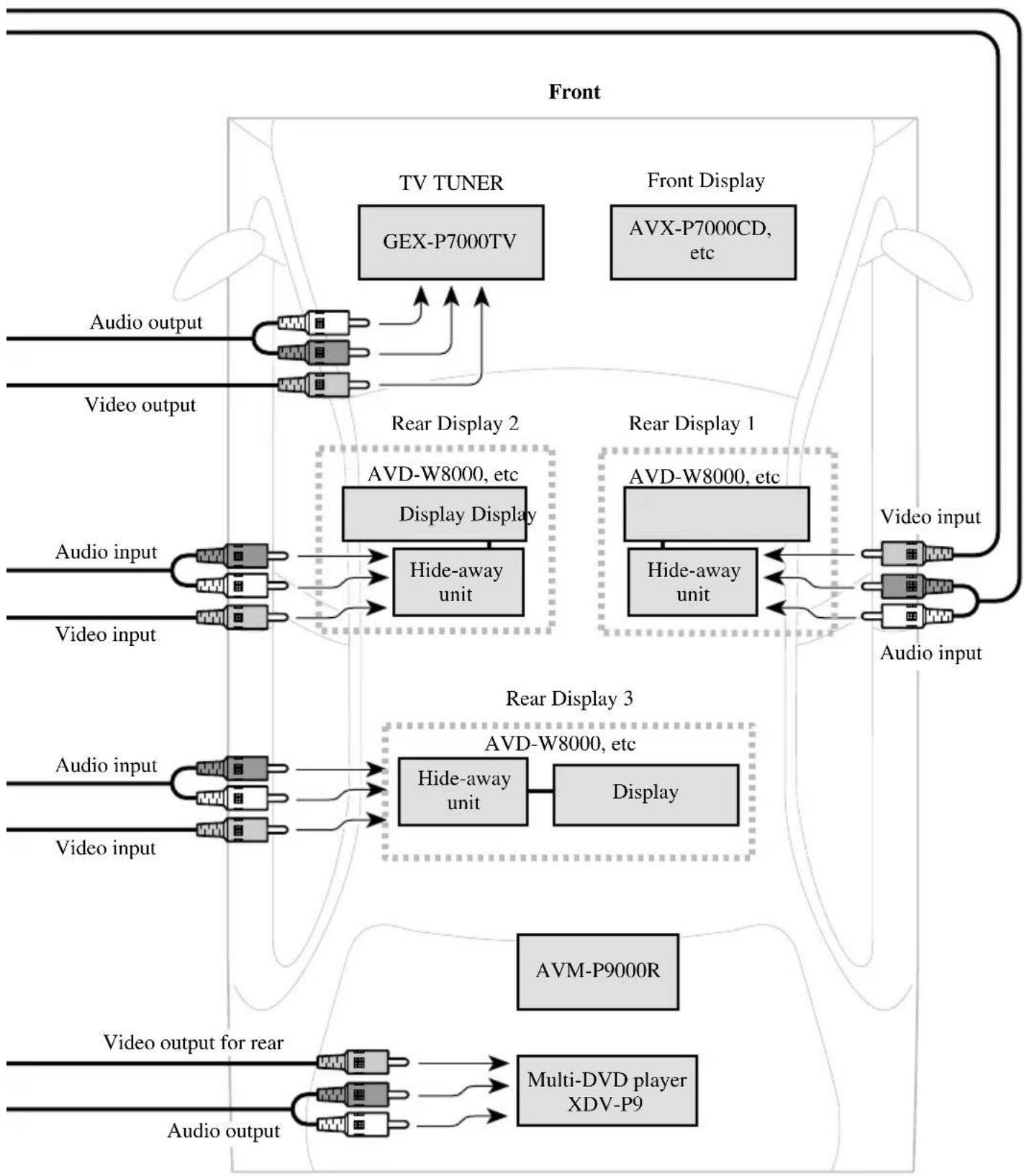
Connecting the System (1)
Rear
Connecting the System (2)
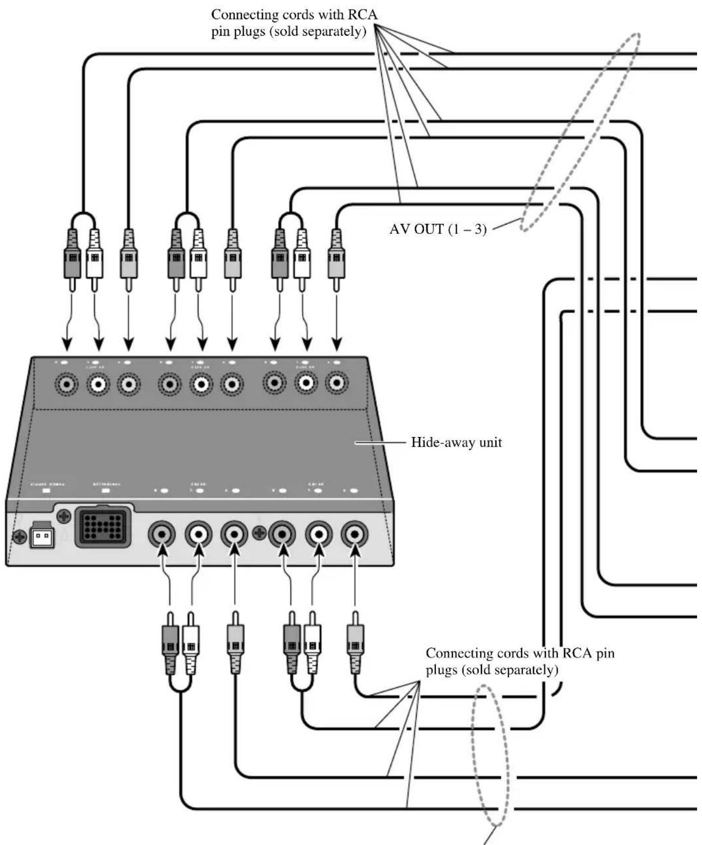
AVIN (2-3)
Rear
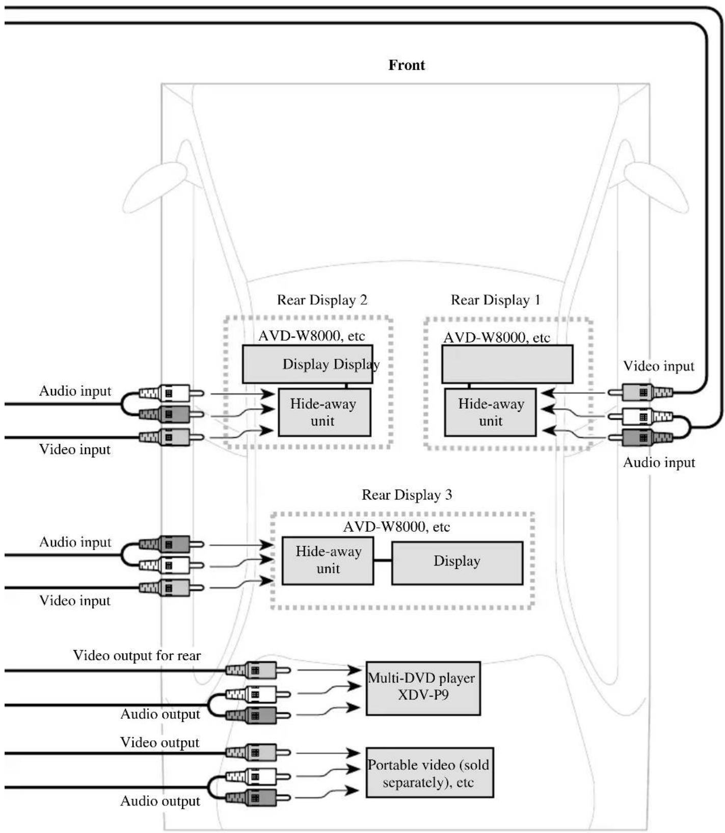
Connecting the Audio / Video equipment
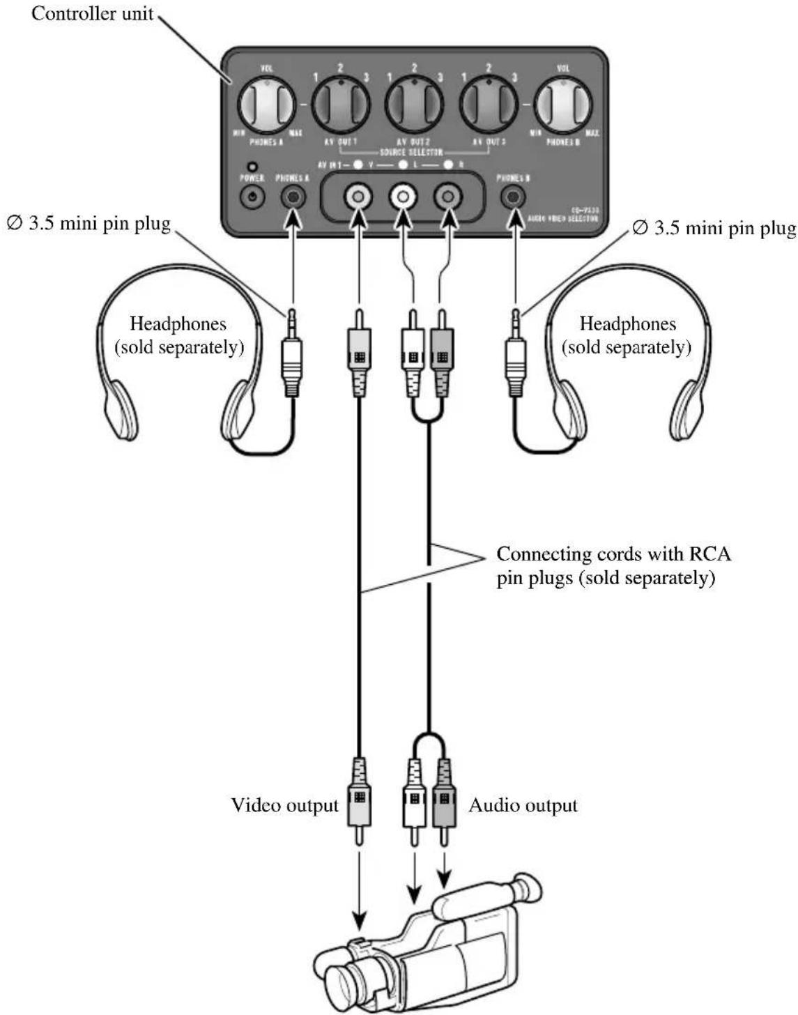
8mm video, vehicle-mounted portable video, etc.
Note:
- Before finally installing the unit, connect the wiring temporarily, making sure it is all connected up properly, and the unit and the system work properly.
- Use only the parts included with the unit to ensure proper installation. The use of unauthorized parts can cause malfunctions.
- Install the unit where it does not get in the driver's way and cannot injure the passenger if there is a sudden stop, like an emergency stop.
- When mounting this product, make sure none of the leads are trapped between this product and the surrounding metalwork or fittings.
- Do not mount this product near the heater outlet, where it would be affected by heat, or near the doors, where rainwater might splash onto it.
- If this product is installed in the passenger compartment, anchor it securely so it does not break free while the car is moving, and cause injury or an accident.
- If this product is installed under a front seat, make sure it does not obstruct seat movement. Route all leads and cords carefully around the sliding mechanism so they do not get caught or pinched in the mechanism and cause a short circuit.
- Install the controller in a safe place where it can be easily operated from the rear seat.
- Never install the controller on the dashboard where it will be exposed to the direct rays of the sun. It could be damaged by high temperatures.
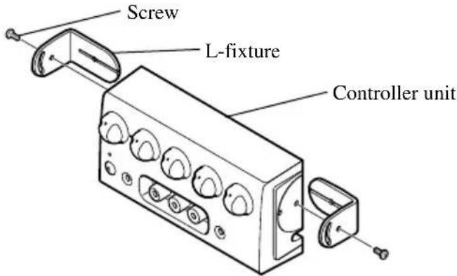
- In attaching L-fixtures to the controller unit with screws, be careful not to overtighten the screws or tighten them slanted. An expanded screw hole might result, disabling attachment of the L-fixtures.
- The L-fixture can be bent to match the installation location.
Installing Hide-away Unit
Installing Controller Unit
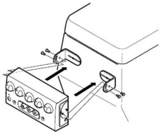
Installation using the L-fixture
The controller unit, when installed with L-fixtures, can be tilted for optimal ease of use. Peel off the paper backing of the double-sided tape of the L-fixture and adhere to the installation location.
1. Attach L-fixtures to the controller unit finger-tight.
Keep the screws loose.
2. Paste double-sided adhesive tape to the intended installation position of the controller unit.
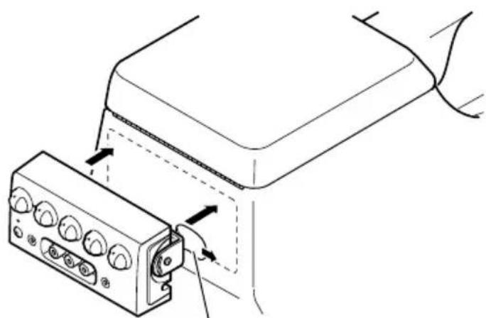
Remove release paper
Note:
-
Bend the L-fixtures to meet the shape of the intended installation position of the controller unit.
-
Release the controller unit from the L-fixtures once.
- Press the L-fixtures firmly against the intended installation position of the controller unit.
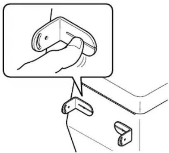
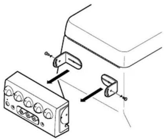
- Attach the controller unit to the L-fixtures.
Keep the screws loose.
6. Adjust the installation angle of the controller unit.
Adjust the angle for optimal ease of use.
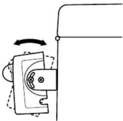
7. Secure the controller unit firmly with the L-fixtures.
Tighten the screws fully.
Note:
- Be careful not to overtighten the screws or tighten them slanted. An expanded screw hole might result, disabling attachment of the L-fixtures.
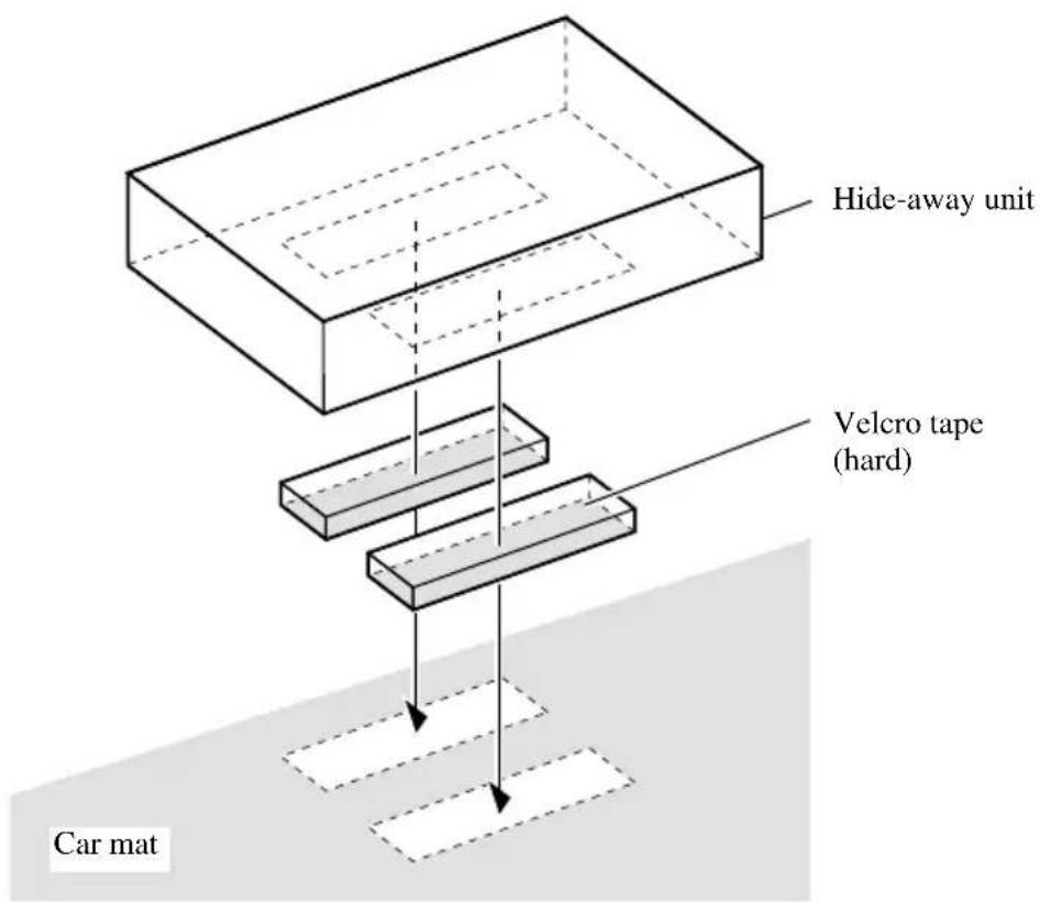
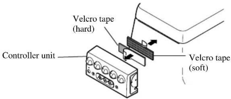
Installation using Velcro tape
Adhere the Velcro tape (hard) (provided) to the back of the controller unit, adhere the Velcro tape (soft) to the installation location and then install.
Controller Unit
VOLUME
PHONES A VOLUME is used to adjust the volume of the headphones connected to PHONES A.
PHONES B VOLUME is used to adjust the volume of the headphones connected to PHONES B.
Rotate counterclockwise to reduce the volume and rotate clockwise to increase the volume.
SOURCE SELECTOR (1-3)
Used to switch the video and audio connected to the AV IN jack (1-3) for each AV OUT jack (1-3).
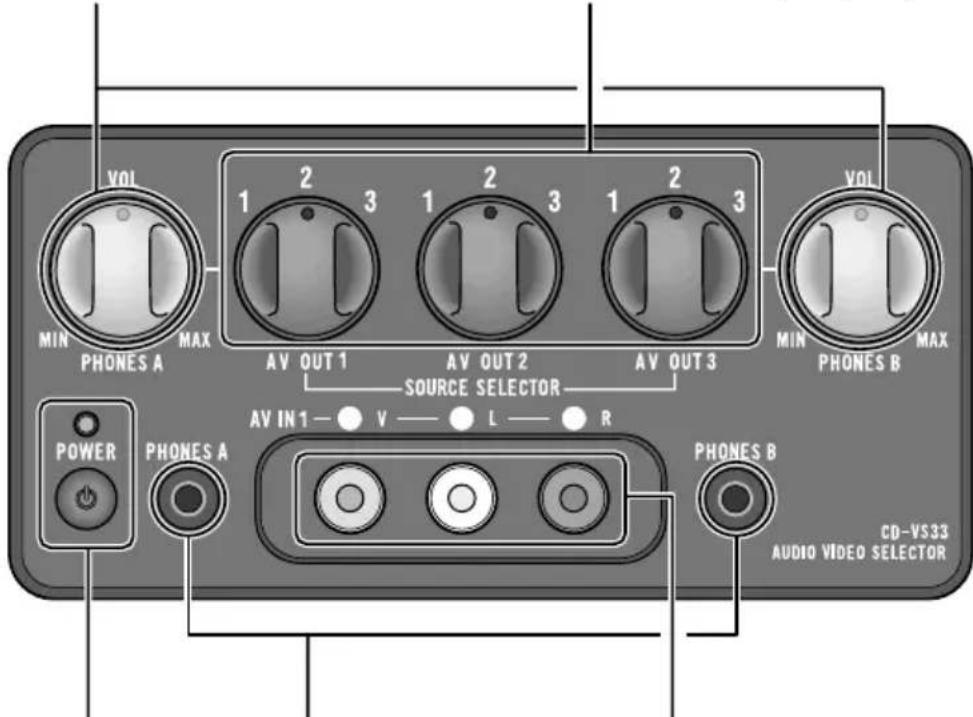
Power indicator, power switch
The power is turned on or off alternately each time the power switch is pressed. The power indicator lights when the power is on.
Headphone output jacks
The mini pin plug of headphones can be connected to PHONES A or PHONES B.
The audio from AV OUT 1 is output from the headphones connected to PHONES A.
The audio from AV OUT 3 is output from the headphones connected to PHONES B.
AV IN jacks (1)
RCA video input (yellow)
RCA audio input (white, red)
Used to connect 8mm video, vehicle-mounted portable video, etc.
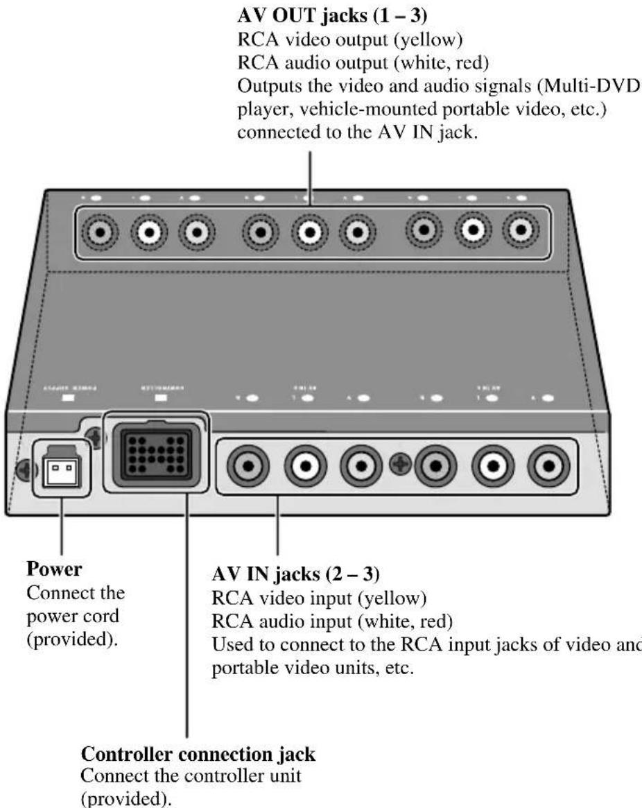
Hide-away Unit
Specifications
Power Source 14.4 V (10.8 - 15.1 V allowable)
Grounding System Negative Type Max. Current Consumption 0.4 A
Audio Output Level .1Vp-p/75Ω
Hide-away Unit Dimensions 160 W)28 H)120 D mm Weight . 0.53 kg
Controller Dimensions 120 W)60 H32 D mm Weight 0.32 kg
Note:
- Specifications and the design are subject to possible modification without notice due to improvements.
#
PIONEER ELECTRONICS (USA) INC.
P.O. Box 1760, Long Beach, California 90801, U.S.A.
TEL: (800) 421-1404
PIONEER EUROPE N.V.
Haven 1087 Keetberglaan 1, 9120 Melsele, Belgium
TEL: (0) 3/570.05.11
PIONEER ELECTRONICS AUSTRALIA PTY. LTD.
178-184 Boundary Road, Braeside, Victoria 3195, Australia
TEL: (03) 9586-6300
PIONEER ELECTRONICS OF CANADA, INC.
300 Allstate Parkway, Markham, Ontario L3R 0P2, Canada
TEL: (905) 479-4411
PIONEER ELECTRONICS DE MEXICO, S.A. de C.V.
San Lorenzo Num 1009 3er piso Desp. 302
Col. Del Valle, Mexico D.F. C.P. 03100
TEL: 5-688-52-90
Published by Pioneer Corporation.
Copyright © 2000 by Pioneer Corporation.
All rights reserved.
Publication de Pioneer Corporation.
Copyright © 2000 Pioneer Corporation.
- Before Using this Product 2
- Connecting the Units 3
- Installation 10
- Part Names And Applications 14
- Specifications 16
- About this Product
- When using this product
- Precaution
- WARNING
- Note:
- Connecting the Power Cord and Controller Unit
- Connecting the System (1)
- Connecting the System (2)
- Connecting the Audio / Video equipment
- Installing Hide-away Unit
- Installing Controller Unit
- Installation using the L-fixture
- Attach L-fixtures to the controller unit finger-tight.
- Paste double-sided adhesive tape to the intended installation position of the controller unit.
- Adjust the installation angle of the controller unit.
- Secure the controller unit firmly with the L-fixtures.
- Installation using Velcro tape
- Controller Unit
- VOLUME
- SOURCE SELECTOR (1-3)
- Power indicator, power switch
- Headphone output jacks
- AV IN jacks (1)
- Hide-away Unit
- Specifications
- #
- PIONEER ELECTRONICS (USA) INC.
- PIONEER EUROPE N.V.
- PIONEER ELECTRONICS AUSTRALIA PTY. LTD.
- PIONEER ELECTRONICS OF CANADA, INC.
- PIONEER ELECTRONICS DE MEXICO, S.A. de C.V.
Brand : PIONEER
Model : CDVS33
Category : Audio-video selector