AR130SS - Basket NuTone - Free user manual and instructions
Find the device manual for free AR130SS NuTone in PDF.
| Product Type | Range Hood |
| Brand | NuTone |
| Model | AR130SS |
| Use | Indoor, household use only |
| Installation | Ducted or ductless (recirculation) with optional charcoal filter |
| Recommended Height Above Cooking Surface | 20 to 25 inches |
| Power Supply | 120 V AC |
| Fan Speeds | 2 speeds (low and high) |
| Lighting | Halogen or LED bulb, GU10 base, max 50 W halogen or 7 W LED (bulb not included) |
| Filter Type | Washable aluminum filter |
| Charcoal Filter (optional) | Part No. S97021380 for ductless installation |
| Duct Material | Metal only (to reduce fire risk) |
| Grounding | Required |
| Warranty | 1 year limited (parts and labor) |
| Replacement Parts Available | Adapter/damper, switches, knobs, grille cover, blower assembly, aluminum filter, wiring cover, bulb holder, recirculation filter |
| Repairability | Spare parts available at www.Broan-NuTone.com |
| Cleaning | Mild detergent for painted surfaces; aluminum filter washable in hot water and non-phosphate detergent |
| Safety | Motor thermal protection, do not use with speed control device, cut power before servicing |
Frequently Asked Questions - AR130SS NuTone
User questions about AR130SS NuTone
0 question about this device. Answer the ones you know or ask your own.
Ask a new question about this device
Download the instructions for your Basket in PDF format for free! Find your manual AR130SS - NuTone and take your electronic device back in hand. On this page are published all the documents necessary for the use of your device. AR130SS by NuTone.
USER MANUAL AR130SS NuTone
natural_image
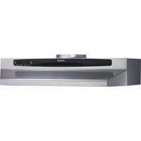
Line drawing of a standard open-top kitchen air conditioner (no text or symbols)READ AND SAVE THESE INSTRUCTIONS
- Use this unit only in the manner intended by the manufacturer. If you have questions, contact the manufacturer at the address or telephone number listed in the warranty.
-
Before servicing or cleaning unit, switch power off at service panel and lock service disconnecting means to prevent power from being switched on accidentally. When the service disconnecting means cannot be locked, securely fasten a prominent warning device, such as a tag, to the service panel.
-
Installation work and electrical wiring must be done by qualified personnel in accordance with all applicable codes and standards, including fire-rated construction codes and standards.
-
Sufficient air is needed for proper combustion and exhausting of gases through the flue (chimney) of fuel burning equipment to prevent backdrafting. Follow the heating equipment manufacturer's guidelines and safety standards such as those published by the National Fire Protection Association (NFPA) and the American Society for Heating, Refrigeration and Air Conditioning Engineers (ASHRAE) and the local code authorities.
-
When cutting or drilling into wall or ceiling, do not damage electrical wiring and other hidden utilities.
-
Ducted fans must always be vented to the outdoors.
-
Do not use this unit with any additional solid-state speed control device.
-
To reduce the risk of fire, use only metal ductwork.
-
This unit must be grounded.
-
When applicable local regulations comprise more restrictive installation and/or certification requirements, the aforementioned requirements prevail on those of this document and the installer agrees to conform to these at his own expense.
TO REDUCE THE RISK OF A RANGE TOP GREASE FIRE:
a) Never leave surface units unattended at high settings. Boilovers cause smoking and greasy spillovers that may ignite. Heat oils slowly on low or medium settings.
b) Always turn range hood ON when cooking at high heat or when flambeing food (i.e.: Crêpes Suzette, Cherries Jubilee, Peppercorn Beef Flambé).
c) Clean ventilating fans frequently. Grease should not be allowed to accumulate on fan, filters or in exhaust ducts.
d) Use proper pan size. Always use cookware appropriate for the size of the surface element.
WARNING ▲ ▲
TO REDUCE THE RISK OF INJURY TO PERSONS IN THE EVENT OF A RANGE TOP GREASE FIRE, OBSERVE THE FOLLOWING\*:
- SMOTHER FLAMES with a close-fitting lid, cookie sheet or metal tray, then turn off the burner. BE CAREFUL TO PREVENT BURNS. IF THE FLAMES DO NOT GO OUT IMMEDIATELY, EVACUATE AND CALL THE FIRE DEPARTMENT.
- NEVER PICK UP A FLAMING PAN — You may be burned.
- DO NOT USE WATER, including wet dishcloths or towels — This could cause a violent steam explosion.
- Use an extinguisher ONLY if:
A. You own a Class ABC extinguisher and you know how to operate it.
B. The fire is small and contained in the area where it started.
C. The fire department has been called.
D. You can fight the fire with your back to an exit.
* Based on "Kitchen Fire Safety Tips" published by NFPA.
CAUTION
- For indoor use only.
- For general ventilating use only. Do not use to exhaust hazardous or explosive materials and vapors.
- To avoid motor bearing damage and noisy and/or unbalanced impellers, keep drywall spray, construction dust, etc. off power unit.
- Your hood motor has a thermal overload which will automatically shut off the motor if it becomes overheated. The motor will restart when it cools down. If the motor continues to shut off and restart, have the hood serviced.
- For best capture of cooking impurities, the bottom of the hood should be at a minimum of 20" and at a maximum of 25" above the cooking surface.
- To reduce the risk of fire and to properly exhaust air, be sure to duct air outside — Donot exhaust air into spaces within walls or ceiling or into attics, crawl space or garage.
- When installing, servicing or cleaning the unit, it is recommended to wear safety glasses and gloves.
- Please read specification label on product for further information and requirements.
INSTALLER: Leave this manual to the homeowner.
HOMEOWNER: Use and care information on page 5.
IMPORTANT
For Non-ducted (Duct free) Installation:
a) Purchase non-ducted filter separately, part number S97021380.
b) Remove and discard damper/duct connector and grille cover plate (See Step 3 in "Preparing the range Hood," on page 3).
c) Follow all steps except steps inside dotted lines.
For Ducted Installation:
Follow all steps, including steps inside dotted lines except Step 3 In "Preparing the range Hood," on page 3.
TOOLS AND MATERIAL REQUIRED
TOOLS

Drill

Flat blade and
Phillips
screwdriver

1¼" Spade bit

Tape measure or ruler
and
pencil

Pliers
For ducted installation ONLY:

Saber saw

[Non-Text]

Metal snips
MATERIALS

Electrical wiring and supplies of type to comply with local codes

Roof or wall cap

Duct and metal foil duct tape

Roof cement or caulk
For installation on kitchen cabinets with recess bottoms only:

Two 1" x 2" x 12" (approximate length) wood strips (purchase locally)

Four 1¼" long flat heat wood screws (purchase locally) to fasten s to cabinet bottom
PLANNING DUCTWORK INSTALLATION
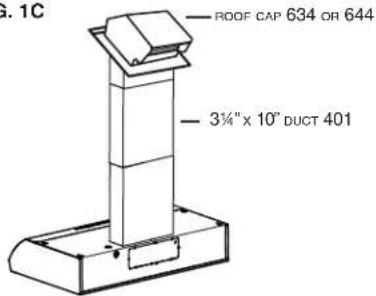
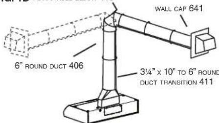
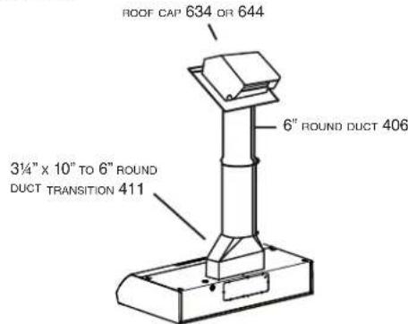
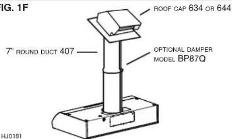
Begin planning ductwork by deciding where the duct will run between the range hood and the outside. For best performance, use the shortest possible duct run and a minimum number of elbows. There are several choices shown - FIGS. 1A - 1F.
If needed, a 3¼" x 10" rectangular ducting range hood can be converted to a round duct by means of a transition.
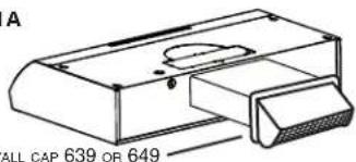
FIG. 1A. Ducting directly through the wall (for range hoods mounted on an exterior wall). Shown are two ways to duct through an outside wall. If a wall cap is used directly off the back of the hood, special care must be taken to make sure that the damper in the damper/duct connector on the hood and damper in the wall cap do not interfere with each other when the hood is operating. This could result in either inadequate air delivery or back drafts. If this condition does exist, remove the hood damper flap. Sometimes when using a wall cap it is easier to duct vertically and then use an elbow as shown in FIG. 1B.
FIG. 1C. Ducting straight up through the roof using 3½" x 10" rectangular duct. (For single story installations.)
FIG. 1D. Ducting between the ceiling joists (for multi-story installations) or through the soffit space above the cabinets (where the soffit connects to an outside wall).
FIG. 1E. Straight up through the roof using 3¼" x 10" to 6" round duct transition and 6" round duct (for single-story installations).
FIG. 1F. Straight up through the roof using 7" round duct (for single-story installations).
FIG. 1A
text_image
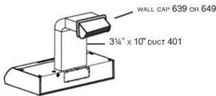
A ALL CAP 639 OR 649FIG. 1B
text_image
WALL CAP 639 OR 649 3¼" x 10" DUCT 401FIG. 1C
text_image
ROOF CAP 634 OR 644 3¾" x 10" DUCT 401FIG. 1D ADJUSTABLE ELBOW 419
text_image
6" ROUND DUCT 406 WALL CAP 641 3¼" x 10" TO 6" ROUND DUCT TRANSITION 411FIG. 1E
text_image
ROOF CAP 634 OR 644 6" ROUND DUCT 406 3¼" x 10" TO 6" ROUND DUCT TRANSITION 411FIG. 1F
text_image
FIG. 1F 7" ROUND DUCT 407 ROOF CAP 634 OR 644 OPTIONAL DAMPER MODEL BP87Q HJ0191PREPARING THE RANGE HOOD
- Unpack hood and check contents. You should have:
1 - Aluminum filter
1 - 3¼" x 10" Damper/duct connector (mounted inside of hood for shipping only) (save the screws)
- Remove wiring box cover. Under cover find the parts bag containing loose hardware.
For non-ducted installation only
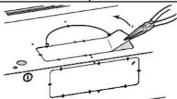
- For non-ducted installation, remove the grille cover plate retaining screw from inside the hood, then pull the grille cover plate out of the hood and discard. (FIG. 3)
NOTE
The grille on front of hood must be open and visible for hood to operate in non-ducted mode.
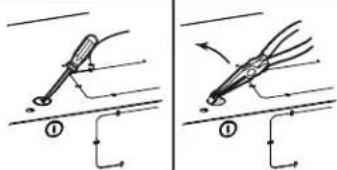
- Remove either top or rear electrical knockout depending upon whether wiring will enter hood from wall or cabinet. (FIG. 4)
DUCTED INSTALLATION ONLY
NOTE
The grille cover plate must NOT be removed to function in ducted mode.
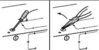
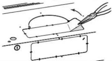
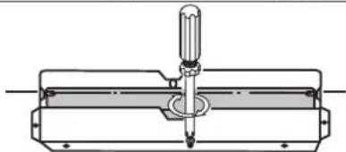
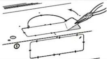
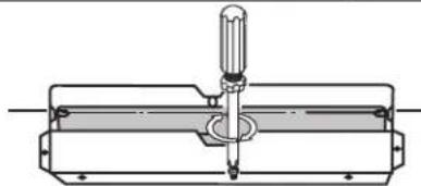
- Remove appropriate duct knockout on hood by inserting screwdriver into edge of knockout and breaking tabs holding knockout to hood. Peel knockout back with pliers. (FIG. 5)
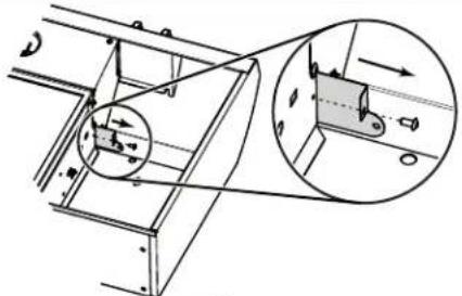
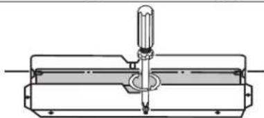
- For 3¼" x 10" ducting only: Fit damper/duct connector over opening and secure in place using screws previously removed in PREPARING THE HOOD section (FIG. 6)
Hinge pins and damper/duct connector should be toward top of hood for ducting through wall or toward back of hood for ducting through cabinet above hood. Seal joint between damper/duct connector and hood with duct tape.
- 7" round ducted discharge only: Install, between 2 duct sections, a 7" round damper (purchase separately). Damper flap must open freely in direction of air flow (away from range hood).
PREPARING THE INSTALLATION LOCATION
NOTE
MOUNT HOOD SO THAT BOTTOM OF HOOD IS 20"-25" ABOVE COOKING SURFACE.
OMIT STEP 8 if range hood will be installed under cabinets with flush bottom.
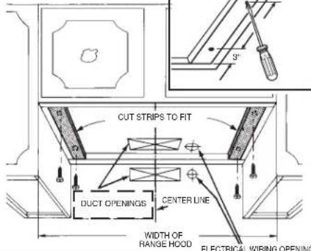
- (For installation on recessed bottom cabinets only.) Attach a wood filler strip at each side of recessed area under cabinet. (Use two 1" x 2" strips cut to length.) If recess is more than 1" use thicker strips. Attach strips with 1¼" screws about 3" from each end. See FIG. 7.
- Measure and mark the following (FIGS. 7 & 8):
a) Electrical line opening
b) Duct opening
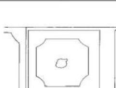
10. Drill four pilot holes in corners of marked duct opening as shown and cut | opening with saber saw or keyhole saw.
11. Use 1¼" drill bit to drill opening for electrical connection in wall or cabinet.
12. Hold hood up against cabinet bottom and trace keyhole slots onto cabinet bottom or filler strips.
13. Screw the four supplied 7/8" wood screws for mounting the hood into the exact center of the narrow end of the keyhole slots marked underneath the cabinet. Allow 3/8" of the screws to project, so the hood can be fitted into place.
FIG. 2
DAMPER/DUCT CONNECTOR
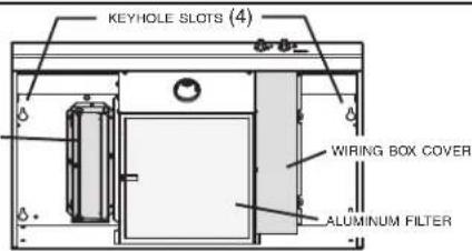
text_image
KEYHOLE SLOTS (4) WIRING BOX COVER ALUMINUM FILTERFIG. 3
natural_image
Technical diagram of a mechanical assembly with circular components and an inset view showing a cylindrical component (no text or symbols)FIG. 4
text_image
Diagram illustrating two mechanical or electrical contact configurations with labeled components and directional arrows indicating movement.FIG. 5
text_image
Technical diagram showing a cutting tool interacting with a rectangular object, with dimension lines and labeled components.FIG. 6
natural_image
Technical line drawing of a mechanical assembly with a central tool and flange (no text or symbols)FIG. 7
text_image
3" CUT STRIPS TO FIT DUCT OPENINGS CENTER LINE WIDTH OF RANGE HOOD ELECTRICAL WIRING OPENINGFIG. 8
3¼" x 10" DUCT
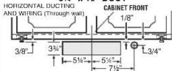
text_image
HORIZONTAL DUCTING AND WIRING (Through wall) CABINET FRONT 1/8" 3/8" 3¼" 5½" 5¾" 7½" 3/4"VERTICAL DUCTING AND WIRING (Through cabinet bottom)
CABINET BOTTOM
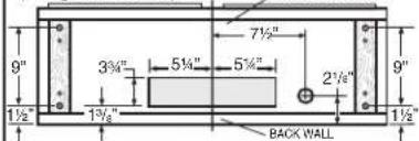
text_image
9" 3½" 5½" 5¾" 2½" 9" 1½" 1¾" BACK WALL 1½"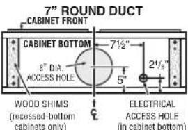
text_image
7" ROUND DUCT CABINET FRONT CABINET BOTTOM 8" DIA. ACCESS HOLE 7½" 5" 2½" WOOD SHIMS (recessed-bottom cabinets only) ELECTRICAL ACCESS HOLE (in cabinet bottom)HMD009A
INSTALLING THE DUCTWORK
NOTE
THESE INSTRUCTIONS WILL FOLLOW THE PLANS MADE ON PAGE 1. START AT THE EXTERIOR AND RUN THE DUCT BACK TO THE RANGE HOOD. FOR BEST PERFORMANCE OF YOUR RANGE HOOD, USE THE SHORTEST POSSIBLE DUCT RUN AND A MINIMUM NUMBER OF ELBOWS. NEVER VENT A RANGE HOOD INTO AN ATTIC SPACE BECAUSE A BUILDUP OF GREASE WILL BECOME A FIRE HAZARD. USE ONLY METAL DUCTWORK (DO NOT USE PLASTIC DUCT). ASSEMBLE SECURELY SO THAT IN CASE OF A GREASE FIRE ON THE RANGE, THE FIRE WILL BE CONTAINED INSIDE METAL DUCT WORK. IT IS A GOOD PRACTICE TO TAPE WITH METAL DUCT TAPE ALL DUCT CONNECTIONS, MAKING THEM BOTH SECURE AND AIR TIGHT.
- Follow appropriate directions below for type of ductwork you are installing:
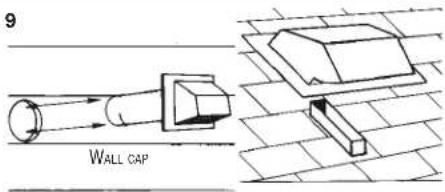
WALL CAP (FIG. 9)
Use a saber saw to cut a hole slightly larger than duct so duct will line up easily with hood. Install casing strips on outside walls finished in siding. Assemble the duct work and tape all joints. Run duct work back to hood. Fasten wall cap to last section of duct and nail or screw cap to wall. Seal all around flange on wall cap with caulking compound for exterior use. Make sure that enough duct runs into the room so that the duct will overlap the damper/duct connector by 3/4" when the hood is installed. ROOF CAP
Cut hole in roof slightly larger than duct so duct will line up easily with hood. Trim shingles around hole so that they will fit snugly around hood of cap when cap is installed. Assemble the ductwork and tape all joints. Run the ductwork down to hood. Trim duct parallel to roof pitch, leaving 3/4" of duct projecting above roof. Seal all around duct with roof cement. Install roof cap, inserting back edge of cap under shingles. Seal around cap with roof cement and seal all nail heads and shingles which were cut or lifted. Make sure that enough duct runs into the room so that the duct will overlap the damper/duct connector by 3/4" when the hood is put into place.
INSTALLING THE RANGE HOOD
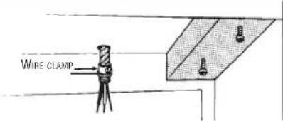
- Bring electrical cable through access hole drilled in wall or bottom of cabinet. Provide 6" wire leads and install proper connector for type of cable being used. Remove lock nut from connector and let prepared cable project through cabinet or wall opening so it is ready for installation into range hood. (FIG. 10)
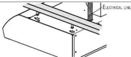
- Position hood in place so that:
a) Electrical line is routed through appropriate knockout opening. This step will have to be accomplished while positioning hood. (FIG. 11) b) Large part of keyhole mounting slots on hood fit onto hood mounting screws projecting from bottom of cabinet. (FIG. 11) c) Damper/duct connector (if present) slides into duct work in wall or cabinet.
- Tighten the four hood mounting screws securely.
- Install locknut on electrical connector and tighten securely.
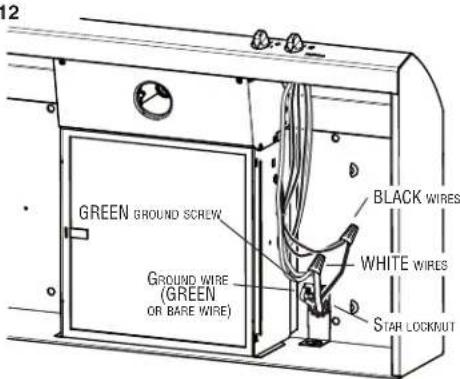
- Make electrical connection using wire nuts to connect WHITE wires to WHITE, BLACK wires to BLACK, and GREEN or bare wire to GREEN ground screw provided (FIG. 12).
- Replace wiring box cover and screw, taking care not to pinch wires.
NOTE
For non-ducted installations only:
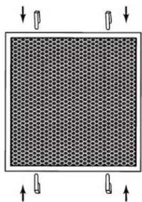
Remove the aluminum filter from the hood. Attach the non-ducted filter (part number S97021380, purchase separately) on the back of aluminum filter (side without pull tab), using 4 provided clips (FIG. 13). Reinstall the aluminum filter.
FIG. 9
text_image
9 WALL CAPFIG. 10
text_image
WIRE CLAMPFIG. 11
text_image
ELECTRICAL LINE Φ4FIG. 12
text_image
GREEN GROUND SCREW GROUND WIRE (GREEN OR BARE WIRE) BLACK WIRES WHITE WIRES STAR LOCKOUTFIG. 13
natural_image
Diagram of a hexagonal grid pattern with four corner arrows pointing outward (no text or symbols)USE AND CARE
CONTROL KNOBS
Right knob controls light and left knob controls blower.
Light: Rotate light knob CLOCKWISE to turn ON the light. Rotate knob COUNTERCLOCKWISE to turn light OFF.
Blower: Rotate blower knob CLOCKWISE to turn blower ON to LOW speed. Further CLOCKWISE rotation sets blower on HIGH speed. Rotate knob fully COUNTERCLOCKWISE (past LOW speed) to turn fan OFF.
CLEANING
Finish Keep your range hood clean using a mild detergent suitable for painted surfaces.
The aluminum filter should be cleaned frequently. Use a warm dishwashing detergent solution.
Clean all-metal filter using a non-phosphate detergent. Discoloration of the filter may occur if using phosphate detergents, or as a result of local water conditions - but this will not affect filter performance. This discoloration is not covered by the warranty. To minimize or prevent discoloration, hand wash filter using a mild detergent.
FILTER REMOVAL
Remove filter by pulling on its plastic tab.
LIGHT BULB REPLACEMENT
Light bulb (not supplied with hood) should be HALOGEN OR LED, but always GU10 base. Align the bulb leads with the small indentations located on the border of the lamp location on hood (see inset in FIG. 14), then install the bulb by placing the bulb leads into their grooves in the socket. NOTE: Do not fold the plate (grey part in FIG. 14) located in the light bulb housing. Gently push upwards and turn clockwise until secured.
Halogen bulb: Shielded halogen bulb, GU10 base, 50 watts maximum.
WARNING
Do not touch lamps during or soon after operation. Burns may occur. In order to prevent the risk of personal injury, only install shielded halogen lamps. Also, never install a cool beam, a dichroic lamp, a lamp not suitable for use in recessed luminaires or identified for use in enclosed fixtures.
LED bulb: 7 watts maximum, GU10 base.
FIG. 14
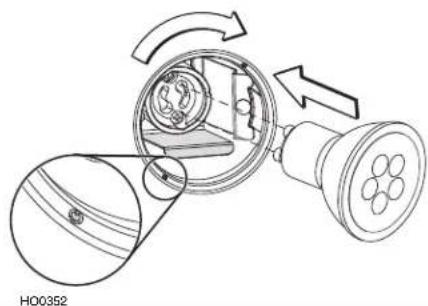
natural_image
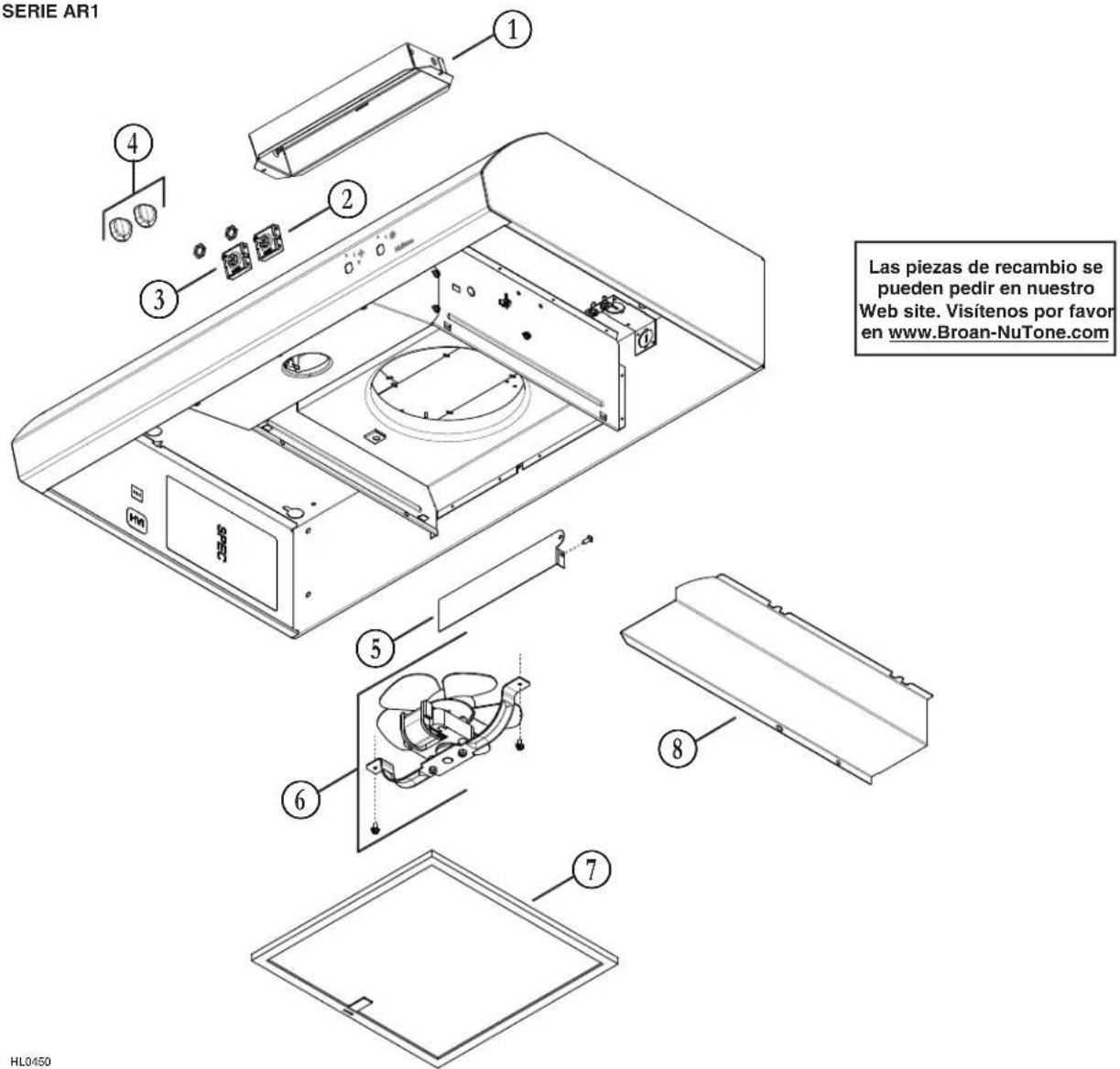
Technical diagram of a mechanical device with internal components and directional arrows indicating motion (no text or symbols)AR1 SERIES RANGE HOOD
text_image
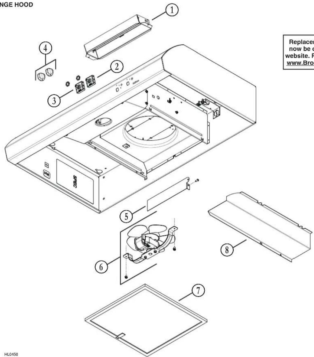
RANGE HOOD 1 2 3 4 5 6 7 8 Replacing now be o website. P www.Broa HL0450HL0450
| KEY No. | PART No. | DESCRIPTION |
| 1 SR740014 3 14 " x | 10" ADAPTER/DAMPER | |
| 2 | S99670656 | LIGHT SWITCH (INCLUDING NUT) |
| 3 | S99670657 | BLOWER SWITCH (INCLUDING NUT) |
| 4 | S600348 K | NOB, BLACK (SET OF 2) |
| S600349 | KNOB, WHITE (SET OF 2) | |
| 5 S98012130 GRILLE COVER PLATE | ||
| 6 | S99080777 | BLOWER ASSEMBLY (INCLUDING SCREWS) |
| 7 S99010467 ALUM NUM FILTER | ||
| 8 S98012128 ELECTRICAL COMPARTMENT COVER | ||
| * S97021380 | NON-DUCTED FILTER(FOR NON-DUCTED INSTALLATION ONLY) | |
| * | S99271677 | BULB HOLDER WITH WIRES |
REPLACEMENT PARTS AND REPAIRS
In order to ensure your unit remains in good working condition, you must use Broan-NuTone LLC genuine replacement parts only. Broan-NuTone LLC genuine replacement parts are specially designed for each unit and are manufactured to comply with all the applicable certification standards and maintain a high standard of safety. Any third party replacement part used may cause serious damage and drastically reduce the performance level of your unit, which will result in premature failing. Broan-NuTone LLC recommends to contact a certified service depot for all replacement parts and repairs.
* Not shown.
Order service parts by PART NO. - NOT by KEY No.
Limited Warranty
Warranty Period and Exclusions: Broan-NuTone LLC and Venmar Ventilation ULC (either being the "Company") warrants to the original consumer purchaser of its product ("you") that the product (the "Product") will be free from material defects in the Product or its workmanship for a period of one (1) year from the date of original purchase (or such longer period as may be required by applicable law).
The limited warranty period for any replacement parts provided by the Company and for any Products repaired or replaced under this limited warranty shall be the remainder of the original warranty period (or such longer period as may be required by applicable law).
This warranty does not cover fluorescent lamp starters, tubes, halogen and incandescent bulbs, fuses, filters, ducts, roof caps, wall caps and other accessories for ducting that may be purchased separately and installed with the Product. This warranty also does not cover (a) normal maintenance and service, (b) normal wear and tear, (c) any Products or parts which have been subject to misuse, abuse, abnormal usage, negligence, accident, improper or insufficient maintenance, storage or repair (other than repair by the Company), (d) damage caused by faulty installation, or installation or use contrary to recommendations or instructions, (e) any Product that has been moved from its original point of installation, (f) damage caused by environmental or natural elements, (g) damage in transit, (h) natural wear of finish, (i) Products in commercial or nonresidential use, or (j) damage caused by fire, flood or other act of God or (k) Products with altered, defaced or removed serial numbers. This warranty covers only Products sold in the United States and Canada by the Company or its U.S. and Canadian distributors authorized by the Company.
This warranty supersedes all prior warranties and, subject to applicable law, is not transferable from the original consumer purchaser.
No Other Warranties: This Limited Warranty contains the Company's sole obligation and your sole remedy for defective products. The foregoing warranties are exclusive and in lieu of any other warranties and conditions, express or implied. THE COMPANY DISCLAIMS AND EXCLUDES ALL OTHER EXPRESS WARRANTIES AND CONDITIONS, AND DISCLAIMS AND EXCLUDES ALL WARRANTIES AND CONDITIONS IMPLIED BY LAW, INCLUDING WITHOUT LIMITATION THOSE OF MERCHANTABILITY AND FITNESS FOR A PARTICULAR PURPOSE. To the extent that applicable law prohibits the exclusion of implied warranties or conditions, the duration of any applicable implied warranty or condition is limited to the period specified for the express warranty above. Some jurisdictions do not allow limitations on how long an implied warranty lasts, so the above limitation may not apply to you. Any oral or written description of the Product is for the sole purpose of identifying it and shall not be construed as an express warranty.
Whenever possible, each provision of this Limited Warranty shall be interpreted in such manner as to be effective and valid under applicable law, but if any provision is held to be prohibited or invalid, such provision shall be ineffective only to the extent of such prohibition or invalidity, without invalidating the remainder of such provision or the other remaining provisions of the Limited Warranty.
Remedy: During the applicable limited warranty period, the Company will, at its option, provide replacement parts for, or repair or replace, without charge, any Product or part thereof, to the extent the Company finds it to be covered by and in breach of this limited warranty under normal use and service. The Company will ship the repaired or replaced Product or replacement parts to you at no charge. You are responsible for all costs for removal, reinstallation and shipping, insurance or other freight charges incurred in the shipment of the Product or part to the Company. If you must send the Product or part to the Company, as instructed by the Company, you must properly pack the Product or part—the Company is not responsible for damage in transit. The Company reserves the right to utilize reconditioned, refurbished, repaired or remanufactured Products or parts in the warranty repair or replacement process. Such Products and parts will be comparable in function and performance to an original Product or part and warranted for the remainder of the original warranty period (or such longer period as may be required by applicable law).
Company reserves the right, in its sole discretion, to refund the money actually paid by you for the Product in lieu of repair or replacement. If the Product or component is no longer available, replacement may be made with a similar product of equal or greater value, at Company's sole discretion. This is your sole and exclusive remedy for breach of this limited warranty.
Exclusion of Damages: THE COMPANY'S OBLIGATION TO PROVIDE REPLACEMENT PARTS, OR REPAIR, REPLACE OR REFUND, AT THE COMPANY'S OPTION, SHALL BE YOUR SOLE AND EXCLUSIVE REMEDY UNDER THIS LIMITED WARRANTY AND THE COMPANY'S SOLE AND EXCLUSIVE OBLIGATION. THE COMPANY SHALL NOT BE LIABLE FOR INCIDENTAL, INDIRECT, CONSEQUENTIAL OR SPECIAL DAMAGES ARISING OUT OF OR IN CONNECTION WITH THE PRODUCT, ITS USE OR PERFORMANCE. Incidental damages include but are not limited to such damages as loss of time and loss of use. Consequential damages include but are not limited to the cost of repairing or replacing other property which was damaged if the Product does not work properly.
THE COMPANY SHALL NOT BE LIABLE TO YOU, OR TO ANYONE CLAIMING UNDER YOU, FOR ANY OTHER OBLIGATIONS OR LIABILITIES, INCLUDING, BUT NOT LIMITED TO, OBLIGATIONS OR LIABILITIES ARISING OUT OF BREACH OF CONTRACT OR WARRANTY, NEGLIGENCE OR OTHER TORT OR ANY THEORY OF STRICT LIABILITY, WITH RESPECT TO THE PRODUCT OR THE COMPANY'S ACTS OR OMISSIONS OR OTHERWISE.
Some jurisdictions do not allow the exclusion or limitation of incidental or consequential damages, so the above limitation or exclusion may not apply to you. This warranty gives you specific legal rights, and you may also have other rights, which vary from jurisdiction to jurisdiction. The disclaimers, exclusions, and limitations of liability under this warranty will not apply to the extent prohibited by applicable law.
This warranty covers only replacement or repair of defective Products or parts thereof at the Company's main facility and does not include the cost of field service travel and living expenses.
Any assistance the Company provides to or procures for you outside the terms, limitations or exclusions of this limited warranty will not constitute a waiver of such terms, limitations or exclusions, nor will such assistance extend or revive the warranty.
The Company will not reimburse you for any expenses incurred by you in repairing or replacing any defective Product, except for those incurred with the Company's prior written permission.
How to Obtain Warranty Service: To qualify for warranty service, you must (a) notify the Company at the address or telephone number stated below within seven (7) days of discovering the covered defect, (b) give the model number and part identification and (c) describe the nature of any defect in the Product or part. At the time of requesting warranty service, you must present evidence of the original purchase date. If you cannot provide a copy of the original written limited warranty, then the terms of the Company's most current written limited warranty for your particular product will control. The most current limited written warranties for the Company's products can be found at www.Broan-NuTone.com and www.nutone.ca
Broan-NuTone LLC 926 West State Street, Hartford, WI 53027 www.Broan-NuTone.com 1-800-558-1711
Venmar Ventilation ULC, 550 Lemire Blvd., Drummondville, Québec, Canada J2C 7W9 www.nutone.ca 1-877-896-1119
NuTone®
HOTTES DE CUISINIÈRE DE SÉRIE AR1 À 4 CONFIGURATIONS
AUX É.-U., ENREGISTREZ VOTRE PRODUIT EN LIGNE À WWW.BROAN-NUTONE.COM
AU CANADA, ENREGISTREZ VOTRE PRODUIT EN LIGNE À : WWW.NUTONE.CA
natural_image
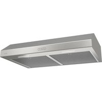
Line drawing of a standard open-top kitchen air conditioner (no text or symbols)LIRE ET CONSERVER CES INSTRUCTIONS
⚠ CONÇUE POUR USAGE DOMESTIQUE SEULEMENT.
AVERTISSEMENT
AFIN DE RÉDUIRE LES RISQUES D'INCENDIE, D'ÉLECTROCUTION OU DE BLESSURES CORPORELLES, SUIVEZ LES DIRECTIVES SUIVANTES :
natural_image
Technical diagram of a mechanical assembly with cross-sectional view and dimension arrows (no text or labels)FIG. 4
text_image
Diagram illustrating two mechanical or electrical setups with labeled components and directional arrows indicating motion or force.FIG. 5
text_image
Technical diagram showing a cutting tool interacting with a rectangular object, with labeled components and directional arrows indicating motion or movement.FIG. 6
natural_image
Technical line drawing of a mechanical assembly with a screwdriver inserted into a cylindrical component (no text or symbols)FIG. 7
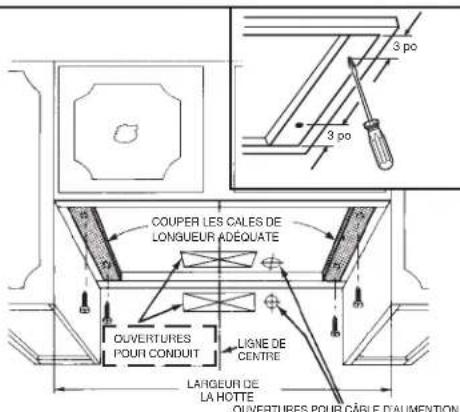
text_image
COUPER LES CALES DE LONGUEUR ADÉQUATE OUVERTURES POUR CONDUIT LIGNE DE CENTRE LARGEUR DE LA HOTTE OUVERTURES POUR CÂBLE D'ALIMENTONFIG. 8 CONDUIT DE 3 14 PO × 10 PO
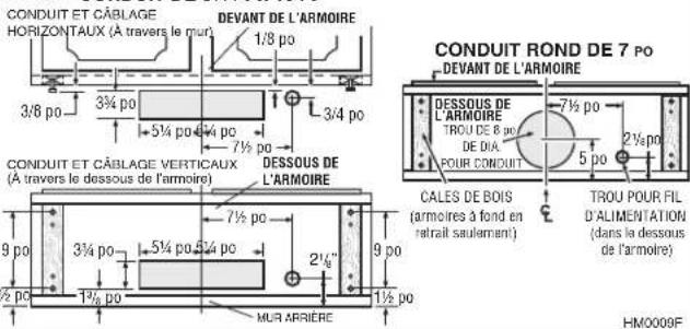
text_image
CONDUIT ET CÂBLAGE HORIZONTAUX (A travers le mur) DEVANT DE L'ARMOIRE 1/8 po 3/4 po 5½ po 7½ po 3/8 po 5½ po 7½ po CONDUIT ET CÂBLAGE VERTICAUX (A travers le dessous de l'armoire) DESSOUS DE L'ARMOIRE 9 po 3½ po 5½ po 2½" MUR ARRIÈRE 9 po 1½ po CONDUIT ROND DE 7 Po DEVANT DE L'ARMOIRE DESSOUS DE L'ARMOIRE TROU DE 6 po DIA POUR CONDUIT 7½ po 5 po 2½ po CALES DE BOIS (armoires à fond en retrait saulement) TROU POUR FIL D'ALIMENTATION (dans la dessous de l'armoire) HM0009FINSTALLATION DU CONDUIT
NOTE
CES INSTRUCTIONS SUIVRONT LES PLANS FAITS EN PAGE 1. COMMENCER PAR L'EXTÉRIEUR ET ACHEMINER LE CONDUIT VERS LA HOTTE.
POUR UNE MEILLEURE PERFORMANCE DE VOTRE HOTTE, UTILISER UN RÉSEAU DE CONDUITS LE PLUS COURT POSSIBLE ET UNE QUANTITÉ MINIMALE DE COUDES.
NE JAMAIS ÉVACUER L'AIR D'UNE HOTTE DANS UN GRENIER CAR UNE ACCUMULATION DES GRAISSES DEVIENDRA UN RISQUE D'INCENDIE. N'UTILISER QUE DES CONDUITS DE MÉTAL (NE PAS UTILISER DE CONDUITS DE PLASTIQUE). LES ASSEMBLER SÉCURITAIREMENT POUR QU'EN CAS DE FEU DE GRAISSES SUR LA SURFACE DE CUISSON, LE FEU SERA CONTENU À L'INTÉRIEUR DES CONDUITS DE MÉTAL.
IL EST RECOMMANDÉ DE SCELLER AVEC DU RUBAN MÉTALLIQUE À CONDUIT TOUS LES RACCORDS DE CONDUITS, LES RENDANT AINSI SÉCURITAIRES ET ÉTANCHES.
natural_image
Diagram of a hexagonal grid pattern with four small protrusions at the top and bottom corners (no text or symbols)UTILISATION ET ENTRETIEN
BOUTONS DE COMMANDES
REPLACEMENT DE L'AMPOULE
natural_image
Technical diagram of a mechanical device with internal components and directional arrows indicating motion (no text or symbols)natural_image
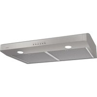
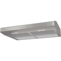
Line drawing of a rectangular kitchen fan with a flat top and side button (no text or symbols)LEA Y GUARDE ESTAS INSTRUCCIONES
▲ DESTINADAS ÚNICAMENTE PARA COCINAS DOMÉSTICAS
ADVERTENCIA
PARA REDUCIR EL RIESGO DE INCENDIO, CHOQUE ELECTRICO, O LESION A PERSONAS, PROCURE LO SIGUIENTE:
natural_image
Technical diagram of a mechanical assembly with cross-section and detail views (no text or symbols)FIG. 4
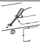
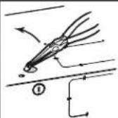
FIG. 5
text_image
Technical diagram showing a cutting tool interacting with a rectangular object, with dimension lines and a labeled section (①)FIG. 6
natural_image
Technical line drawing of a mechanical assembly with a central tool and flange (no text or symbols)FIG. 7
natural_image
Pure geometric diagram with concentric rectangles and a central oval (no text or symbols)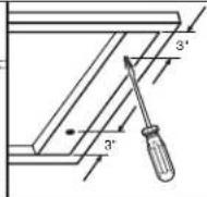
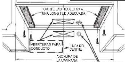
text_image
CORTE LAS REGLETAS A UNA LONGITUD ADECUADA ABERTURAS PARA CONDUCTO LINEA DEL CENTRE ANCHURA DE LA CAMPAÑAnatural_image
Diagram of a square grid pattern with four small protrusions and directional arrows, no text or symbols present.USO Y CUIDADO
BOTONES DE CONTROL
natural_image
Technical diagram of a mechanical device with internal components and directional arrows indicating motion (no text or symbols)CAMPANA DE SERIE AR1
Broan-NuTone LLC 926 West State Street, Hartford, WI 53027 www.Broan-NuTone.com 1-800-558-1711
Venmar Ventilation ULC, 550 Lemire Blvd., Drummondville, Québec, Canada J2C 7W9 www.nutone.ca 1-877-896-1119