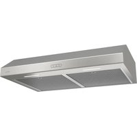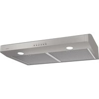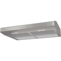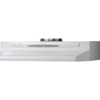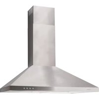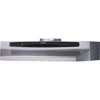
HDN6430SS - Basket NuTone - Free user manual and instructions
Find the device manual for free HDN6430SS NuTone in PDF.


User questions about HDN6430SS NuTone
0 question about this device. Answer the ones you know or ask your own.
Ask a new question about this device
Download the instructions for your Basket in PDF format for free! Find your manual HDN6430SS - NuTone and take your electronic device back in hand. On this page are published all the documents necessary for the use of your device. HDN6430SS by NuTone.
USER MANUAL HDN6430SS NuTone
IMPORTANT SAFETY INSTRUCTIONS
WARNING - TO REDUCE THE RISK OF FIRE, ELECTRIC SHOCK, OR INJURY TO PERSONS, OBSERVE THE FOLLOWING:
- Use this unit only in the manner intended by the manufacturer. If you have any questions, contact the manufacturer at the address or telephone number listed in the warranty.
- Before servicing or cleaning unit, switch power off at service panel and lock service panel to prevent power from being switched on accidentally. When the service disconnecting means cannot be locked, securely fasten a prominent warning device, such as a tag, to the service panel.
- Installation work and electrical wiring must be done by qualified person(s) in accordance with all applicable codes and standards - including fire-rated construction codes and standards.
- Sufficient air is needed for proper combustion and exhausting of gases through the flue (chimney) of fuel burning equipment to prevent backdrafting. Follow the heating equipment manufacturer's guidelines and safety standards such as those published by the National Fire Protection Association (NFPA), and the American Society for Heating, Refrigeration and Air Conditioning Engineers (ASHRAE), and local code authorities.
- When cutting or drilling into wall or ceiling, do not damage electrical wiring and other hidden utilities.
- This unit must be grounded.
- Ducted fans must always be vented to the outdoors.
- To reduce the risk of fire, use only metal ductwork.
- When applicable local regulations comprise more restrictive installation and/or certification requirements, the aforementioned requirements prevail on those of this document and the installer agrees to conform to these at his own expenses.
- When performing installation, servicing or cleaning this unit, it is recommended to wear safety glasses and gloves.
TO REDUCE THE RISK OF A RANGE TOP GREASE FIRE:
- Never leave surface units unattended at high settings. Boilovers cause smoking and greasy spillovers that may ignite. Heat oils slowly on low or medium setting.
- Always turn hood ON when cooking at high heat or when flambeing food (i.e.: Crêpes Suzette, Cherries Jubilee, Peppercorn Beef Flambé).
- Clean ventilating fans frequently. Grease should not be allowed to accumulate on fan or filter.
- Use proper pan size. Always use cookware appropriate for the size of the surface element.
TO REDUCE THE RISK OF INJURY TO PERSONS IN THE EVENT OF A RANGE TOP GREASE FIRE, OBSERVE THE FOLLOWING\*:
- SMOTHER FLAMES with a close-fitting lid, cookie sheet, or metal tray, then turn off the burner. BE CAREFUL TO PREVENT BURNS. If the flames do not go out immediately, EVACUATE AND CALL THE FIRE DEPARTMENT.
- NEVER PICK UP A FLAMING PAN - you may be burned.
- DO NOT USE WATER, including wet dishcloths or towels - a violent steam explosion will result.
- Use an extinguisher ONLY if:
A. You know you have a Class ABC extinguisher, and you already know how to operate it.
B. The fire is small and contained in the area where it started.
C. The fire department is being called.
D. You can fight the fire with your back to an exit.
*Based on "Kitchen Fire Safety Tips" published by NFPA.
REGISTER YOUR PRODUCT ON LINE AT WWW.NUTONE.CA
IMPORTANT SAFETY INSTRUCTIONS
- For indoor use only.
- For general ventilating only. Do not use to exhaust hazardous or explosive materials and vapors.
- To reduce the risk of fire or electrical shock, this range hood should not be used with an additional solid-state speed control device.
- To reduce the risk of shock, disconnect power before servicing.
- To reduce the risk of fire and to properly exhaust air, be sure to duct air outside. Do not vent exhaust air into spaces within walls or ceilings or into attics, crawl spaces or garages.
HORIZONTAL DISCHARGE THROUGH WALL
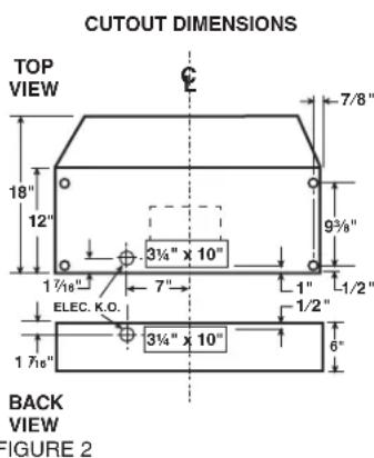
CUTOUT DIMENSIONS

text_image
KITCHEN CABINET 7" 17½" 3¾" 5½" 10¼" WIRING CUTOUT SUPPLIED DUCT TRANSITION RANGE HOOD REMOVE DAMPER FLAP FROM TRANSITION FOR THIS INSTALLATION WALL WALL CAP FIGURE 1VERTICAL OR HORIZONTAL DISCHARGE USING 3¼" x 10" DUCT
text_image
CUTOUT DIMENSIONS TOP VIEW 18" 12" 7/8" 93/8" 1 7/18" ELEC. K.O. 7" 1" 1/2" 1 7/16" 3 3/4" x 10" 3 3/4" x 10" 6" BACK VIEW FIGURE 2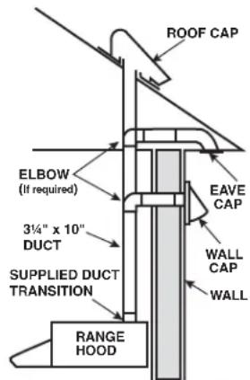
text_image
ROOF CAP ELBOW (If required) 3¼" x 10" DUCT SUPPLIED DUCT TRANSITION EAVE CAP WALL CAP WALL RANGE HOODVERTICAL DISCHARGE USING 7" ROUND DUCT (TRANSITION NOT INCLUDED)
text_image
CUTOUT DIMENSIONS TOP VIEW 18" 12" 7"DIA" 93/9" 4 7/8" 17/16" ELEC. K.O. 7" 1" 1/2" 1/2" 6" BACK VIEW FIGURE 3 ROOF CAP ADJUSTABLE ELBOW ROOF 7" ROUND DUCT REMOVE BOTH 3¼" x 10" AND 4½" x 8" KNOCKOUTS FOR 7" DUCT RANGE HOODINSTALLATION INSTRUCTIONS FOR HDN64 SERIES RANGE HOOD READ & SAVE THESE INSTRUCTIONS
PLANNING
- This hood can be connected to ductwork to discharge through the top or the back of the hood to outside. It can also be installed without ducts to return filtered air back into the room. For a ductless installation, a separate filter is required. Order conversion kit FKM65.
- Mounting height MUST BE at a minimum of 22" and at a maximum of 30" above the cooking surface from the bottom edge of the range hood.
- The hood shall be mounted to the bottom of a standard wall cabinet. If the hood must be mounted directly to a wall, secure the hood to wall studs.
- All wiring must comply with local codes and the unit must be properly grounded. Connection should be made to a 110-120 VAC lighting circuit (15A) in the circuit breaker or fuse box.
IF THE RANGE HOOD IS TO BE DUCTED:
- Ductwork can be installed vertically or horizontally.
- Duct runs should be as short as possible.
- Avoid the use of elbows.
- Use metal duct tape at all joints.
- Do not use duct smaller than the discharge on the hood.
NON DUCTED:
- Disregard instructions for knockout.
- Discard the transition, it will not be used.
PREPARATION
- Use the dimensional drawing to lay out the range hood's mounting holes, wiring access and ductwork.
- Make cut-outs for wiring and ductwork.
- If the hood is to be ducted, install the ductwork so that it is flush to the range hood's mounting surface.
- Refer to Figure 1 if the range hood is to be installed with a horizontal discharge.
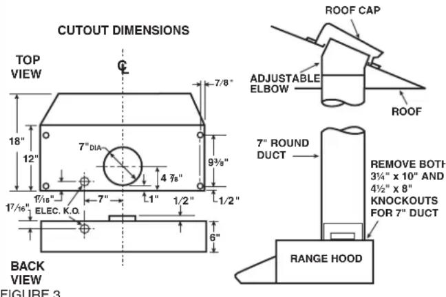
- Refer to Figure 2 if the range hood is to be installed with a vertical discharge.
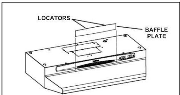
- Remove the necessary duct opening and wiring knockout from the range hood. NOTE: If the range hood is to be installed as a ducted unit, install baffle plate (refer to figure 4) by sliding into place behind grille. Use locator bumps to orient the grille.
NOTE: If the range hood is to be installed as a ductless unit, do not remove any knockouts.
- Run two-conductor wires (with ground) from a power source to the hood location. Bring approximately 12" of wiring through wiring hole in cabinet.
- Drill four 3/32" diameter pilot holes at points where mounting holes are marked in the filler strips or cabinet bottom.
- Insert four (4) mounting screw (not supplied), leaving approximately 1/4" of thread exposed. Use no. 8 or no. 10 round head screws.
INSTALLATION
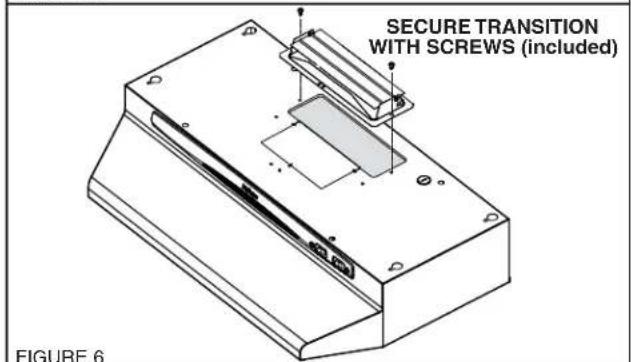
- Refer to Figure 6 for a vertical discharge installation.
Secure the 3¼" x 10" transition (if used) to top of hood. Refer to Figure 7 for a horizontal discharge installation.
If using the supplied 3 ^1/4 " x 10" duct transition, remove the damper from the transition to prevent possible venting interference. Position transition into wall cutout (the transition does not fasten to the hood).
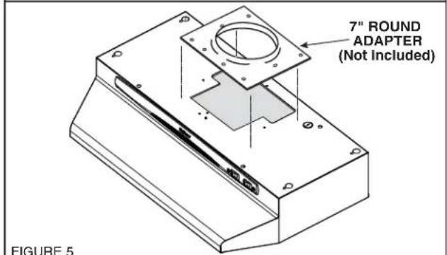
Refer to Figure 5 for 7" round discharge installation. Secure 7" round adaptor to top of hood using screws provided.
- Feed the wiring through the access hole and into the electrical box.
- Align hood's keyhole mounting slots over the four (4) partially installed screws.
- Making sure the duct position over the hood's duct transition (or adaptor), push the hood against the rear wall. Secure hood by tightening screws
- Using a long blade screwdriver, reach into the discharge opening and make sure the damper operates freely.
WIRING CONNECTIONS
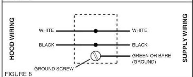
All wiring connections must comply with local code and the unit must be properly grounded.
- Make sure box connector is secure.
- Refer to Figure 8. Make wiring connections.
- Replace electrical box cover and secure with screw.
text_image
LOCATORS BAFFLE PLATEFIGURE 4
text_image
7" ROUND ADAPTER (Not Included) FIGURE 5FIGURE 5
text_image
SECURE TRANSITION WITH SCREWS (included) FIGURE 6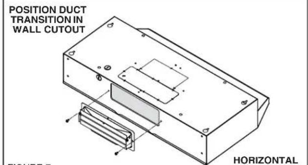
text_image
POSITION DUCT TRANSITION IN WALL CUTOUT HORIZONTAL FIGURE 7FIGURE 7
text_image
HOOD WIRING WHITE BLACK GROUNDS SCREW WHITE BLACK GREEN OR BARE (GROUND) SUPPLY WIRING FIGURE 8INSTALLATION INSTRUCTIONS FOR HDN64 SERIES RANGE HOOD READ & SAVE THESE INSTRUCTIONS
COMPLETING ASSEMBLY
- Install a 75 W (maximum) light bulb in the receptacle.
- Install filter and light lens assembly.
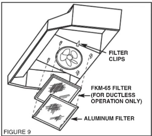
- For ductless use with charcoal filter (FKM-65): Install 2 filter clips by sliding into the receivers on the sides of the hood fan housing.
See Figure 9.
IMPORTANT: The aluminium filter should be removed once a week and washed in hot detergent water. Rinse in clear, warm water and shake off excessive moisture before replacing. The filter may also be cleaned in your dishwasher. Always install the aluminium filter with the domed side away from the fan.
IN A NON-DUCTED INSTALLATION
Refer to Figure 9. In non-ducted installations use FKM-65 filter and replace every 3-6 months as needed. Always install the FKM-65 filter first (nearest fan) with carbon side towards fan and the aluminium filter second. Install filter clips by sliding into brackets on side of air chamber.
CLEANING
The hood should be wiped off occasionally both inside and outside using warm water, mild dish detergent and a soft cloth. Never use scouring powders, steel wool pads or any other abrasive cleaners, which will destroy the hood's finish.
text_image
FILTER CLIPS FKM-65 FILTER (FOR DUCTLESS OPERATION ONLY) ALUMINUM FILTER FIGURE 9BROAN-NUTONE CANADA ONE-YEAR LIMITED WARRANTY
Broan-NuTone Canada warrants to the original consumer purchaser of its products that such products will be free from defects in materials and workmanship for a period of one year from the date of original purchase. THERE ARE NO OTHER WARRANTIES, EXPRESSED OR IMPLIED, INCLUDING, BUT NOT LIMITED TO, IMPLIED WARRANTIES OF MERCHANTABILITY OR FITNESS FOR A PARTICULAR PURPOSE.
During this one-year period, Broan-NuTone Canada will, at its option, repair or replace, without charge, any product or part which is found to be defective under normal use and service.
THIS WARRANTY DOES NOT EXTEND TO FLUORESCENT LAMP STARTERS AND TUBES. This warranty does not cover (a) normal maintenance and service or (b) any products or parts which have been subject to misuse, negligence, accident, improper maintenance or repair (other than by Broan-NuTone Canada), faulty installation or installation contrary to recommended installation instructions.
The duration of any implied warranty is limited to the one-year period as specified for the express warranty.
BROAN- NUTONE CANADA'S OBLIGATION TO REPAIR OR REPLACE, AT BROAN-NUTONE CANADA'S OPTION, SHALL BE THE PURCHASER'S SOLE AND EXCLUSIVE REMEDY UNDER THIS WARRANTY. BROAN-NUTONE CANADA SHALL NOT BE LIABLE FOR INCIDENTAL, CONSEQUENTIAL OR SPECIAL DAMAGES ARISING OUT OF OR IN CONNECTION WITH PRODUCT USE OR PERFORMANCE. Some jurisdictions do not allow the exclusion or limitation of incidental or consequential damages, so the above limitation or exclusion may not apply to you.
This warranty gives you specific legal rights, and you may also have other rights, which vary by jurisdiction. This warranty supersedes all prior warranties. To qualify for warranty service, you must (a) notify Broan-NuTone Canada at the address or telephone number below, (b) give the model number and part identification and (c) describe the nature of any defect in the product or part. At the time of requesting warranty service, you must present evidence of the original purchase date.
Date of Installation Builder or Installer
Model No. and Product Description
IF YOU NEED ASSISTANCE OR SERVICE:
For the location of your nearest Broan-NuTone Canada Incorporated dealer
Dial Free 1-888-882-7626
Please be prepared to provide:
Product model number • Date and Proof of Purchase • The nature of the difficulty
Broan-NuTone Canada Incorporated
1140 Tristar Drive, Mississauga, Ontario, Canada L5T 1H9
www.nutone.ca
IMPORTANTES DIRECTIVES DE SÉCURITÉ
AVERTISSEMENT : AFIN DE RÉDUIRE LES RISQUES D'INCENDIE, D'ÉLECTROCUTION OU DE BLESSURES CORPORELLES, OBSERVEZ LES DIRECTIVES SUIVANTES :
text_image
FIXER LA TRANSITION AVEC LES VIS (incluses) FIGURE 6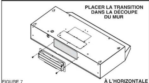
text_image
PLACER LA TRANSITION DANS LA DÉCOUPE DU MUR FIGURE 7 À L'HORIZONTALE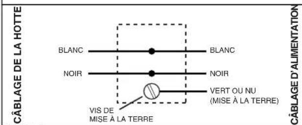
text_image
CÂBLAGE DE LA HOTTE BLANC NOIR VIS DE MISE À LA TERRE BLANC NOIR VERT OU NU (MISE À LA TERRE) CÂBLAGE D'ALIMENTATIONFIGURE 8
DIRECTIVES D'INSTALLATION DES HOTTES DE CUISINIÈRE DE SÉRIE HDN64 LIRE ET CONSERVER CES DIRECTIVES
COMPLÉTER L'ASSEMBLAGE
Broan-NuTone Canada Incorporated
1140, Tristar Drive, Mississauga (Ontario) CANADA L5T 1H9
www.nutone.ca