AC75 - Guitar amp Hartke - Free user manual and instructions
Find the device manual for free AC75 Hartke in PDF.
| Features | Details |
|---|---|
| Amplifier type | Acoustic amplifier |
| Power | 75 Watts |
| Speakers | 1 x 12 inches |
| Channels | 2 channels (instrument and microphone) |
| Inputs | 1 instrument input, 1 microphone input |
| Equalizer | 3 bands (bass, mid, treble) |
| Built-in effects | Reverb, chorus |
| Dimensions | Compact dimensions for easy transport |
| Weight | Approximately 12 kg |
| Usage | Ideal for live concerts and rehearsals |
| Maintenance | Clean regularly, check connections |
| Safety | Do not expose to moisture, use with caution |
| General information | Compatible with various acoustic instruments and microphones |
Frequently Asked Questions - AC75 Hartke
User questions about AC75 Hartke
0 question about this device. Answer the ones you know or ask your own.
Ask a new question about this device
Download the instructions for your Guitar amp in PDF format for free! Find your manual AC75 - Hartke and take your electronic device back in hand. On this page are published all the documents necessary for the use of your device. AC75 by Hartke.
USER MANUAL AC75 Hartke
Copyright 2006, Samson Technologies Corp.
Printed January, 2007 v1.3
Samson Technologies Corp.
45 Gilpin Avenue
Hauppauge, New York 11788-8816v
Phone: 1-800-3-SAMSON (1-800-372-6766)
Fax: 631-784-2201
www.samsontech.com
Caution: To reduce the hazard of electrical shock, do not remove cover or back.
No user serviceable parts inside. Please refer all servicing to qualified personnel.
WARNING: To reduce the risk of fire or electric shock, do not expose this unit to rain or moisture.
The lightning flash with an arrowhead symbol within an equilateral triangle, is intended to alert the user to the presence of un-insulated "dangerous voltage" within the products enclosure that may be of sufficient magnitude to constitute a risk of electric shock to persons.
The exclamation point within an equilateral triangle is intended to alert the user to the presence of important operating and maintenance (servicing) instructions in the literature accompanying the product.
Important Safety Instructions
- Please read all instructions before operating the unit.
- Keep these instructions for future reference.
- Please heed all safety warnings.
- Follow manufacturers instructions.
- Do not use this unit near water or moisture.
- Clean only with a damp cloth.
- Do not block any of the ventilation openings. Install in accordance with the manufacturers instructions.
- Do not install near any heat sources such as radiators, heat registers, stoves, or other apparatus (including amplifiers) that produce heat.
- Do not defeat the safety purpose of the polarized or grounding-type plug. A polarized plug has two blades with one wider than the other. A grounding type plug has two blades and a third grounding prong. The wide blade or third prong is provided for your safety. When the provided plug does not fit your outlet, consult an electrician for replacement of the obsolete outlet.
- Protect the power cord from being walked on and pinched particularly at plugs, convenience receptacles and at the point at which they exit from the unit.
- Unplug this unit during lightning storms or when unused for long periods of time.
- Refer all servicing to qualified personnel. Servicing is required when the unit has been damaged in any way, such as power supply cord or plug damage, or if liquid has been spilled or objects have fallen into the unit, the unit has been exposed to rain or moisture, does not operate normally, or has been dropped.
Introduction 1
Hartke AC75 and AC150 Acoustic Amplifier Features. 2
Guided Tour - Front Panel 3
Guided Tour - Rear Panel 4
Setting Up and Using Your Hartke AC75 and AC150 Acoustic Amplifier. 5 - 10
AC75 and AC150 Set-ups 11
AC75 and AC150 Set-ups 12
AC75 and AC150 Specifications. 72
FRANÇAIS
AC75 und AC150 Setups 40
Introduction 43
Hartke AC75 and AC150 Acoustic Amplifier Features. 44
Guided Tour - Front Panel 45
Guided Tour - Rear Panel 46
Setting Up and Using Your Hartke AC75 and AC150 Acoustic Amplifier. 47 - 52
AC75 and AC150 Set-ups 53
AC75 and AC150 Set-ups 54
AC75 and AC150 Especificaciones sociales. 75
ITALIANO
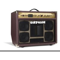
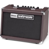
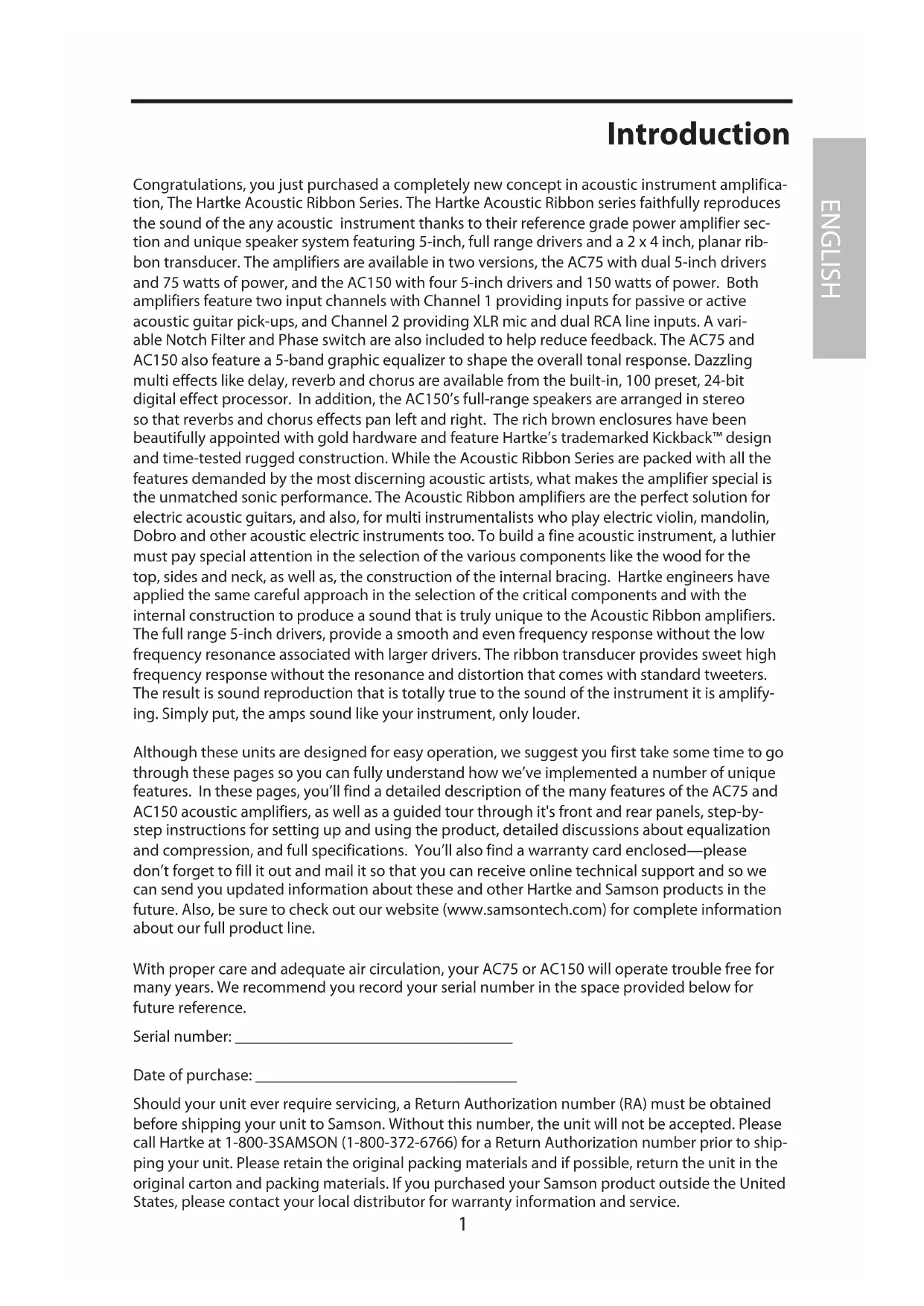
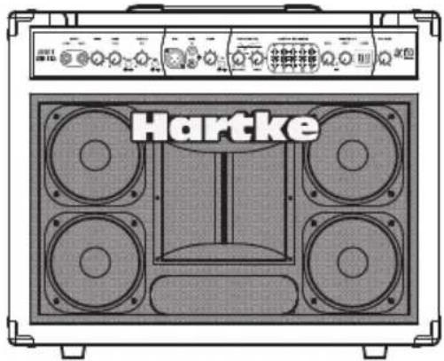
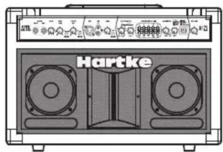
Congratulations, you just purchased a completely new concept in acoustic instrument amplification, The Hartke Acoustic Ribbon Series. The Hartke Acoustic Ribbon series faithfully reproduces the sound of the any acoustic instrument thanks to their reference grade power amplifier section and unique speaker system featuring 5-inch, full range drivers and a 2 × 4 inch, planar ribbon transducer. The amplifiers are available in two versions, the AC75 with dual 5-inch drivers and 75 watts of power, and the AC150 with four 5-inch drivers and 150 watts of power. Both amplifiers feature two input channels with Channel 1 providing inputs for passive or active acoustic guitar pick-ups, and Channel 2 providing XLR mic and dual RCA line inputs. A variable Notch Filter and Phase switch are also included to help reduce feedback. The AC75 and AC150 also feature a 5-band graphic equalizer to shape the overall tonal response. Dazzling multi effects like delay, reverb and chorus are available from the built-in, 100 preset, 24-bit digital effect processor. In addition, the AC150's full-range speakers are arranged in stereo so that reverbs and chorus effects pan left and right. The rich brown enclosures have been beautifully appointed with gold hardware and feature Hartke's trademarked Kickback™ design and time-tested rugged construction. While the Acoustic Ribbon Series are packed with all the features demanded by the most discerning acoustic artists, what makes the amplifier special is the unmatched sonic performance. The Acoustic Ribbon amplifiers are the perfect solution for electric acoustic guitars, and also, for multi instrumentalists who play electric violin, mandolin, Dobro and other acoustic electric instruments too. To build a fine acoustic instrument, a luthier must pay special attention in the selection of the various components like the wood for the top, sides and neck, as well as, the construction of the internal bracing. Hartke engineers have applied the same careful approach in the selection of the critical components and with the internal construction to produce a sound that is truly unique to the Acoustic Ribbon amplifiers. The full range 5-inch drivers, provide a smooth and even frequency response without the low frequency resonance associated with larger drivers. The ribbon transducer provides sweet high frequency response without the resonance and distortion that comes with standard tweeters. The result is sound reproduction that is totally true to the sound of the instrument it is amplifying. Simply put, the amps sound like your instrument, only louder.
Although these units are designed for easy operation, we suggest you first take some time to go through these pages so you can fully understand how we've implemented a number of unique features. In these pages, you'll find a detailed description of the many features of the AC75 and AC150 acoustic amplifiers, as well as a guided tour through it's front and rear panels, step-by-step instructions for setting up and using the product, detailed discussions about equalization and compression, and full specifications. You'll also find a warranty card enclosed—please don't forget to fill it out and mail it so that you can receive online technical support and so we can send you updated information about these and other Hartke and Samson products in the future. Also, be sure to check out our website (www.samsontech.com) for complete information about our full product line.
With proper care and adequate air circulation, your AC75 or AC150 will operate trouble free for many years. We recommend you record your serial number in the space provided below for future reference.
Serial number:
Date of purchase:
Should your unit ever require servicing, a Return Authorization number (RA) must be obtained before shipping your unit to Samson. Without this number, the unit will not be accepted. Please call Hartke at 1-800-3SAMSON (1-800-372-6766) for a Return Authorization number prior to shipping your unit. Please retain the original packing materials and if possible, return the unit in the original carton and packing materials. If you purchased your Samson product outside the United States, please contact your local distributor for warranty information and service.
Hartke AC75 and AC150 Acoustic Amplifier Features
The Hartke AC75 and AC150 Acoustic Ribbon series amplifiers employ the most advanced electronic and speaker design concepts in acoustic instrument amplification. Here are some of their main features:
- The Acoustic Ribbon amplifiers and internal speaker systems have been matched to produce a linear and controlled frequency response via the custom-designed, 5-inch full-range drivers and unique high frequency ribbon transducers.
- The Acoustic Ribbon series feature a custom designed, planar ribbon high frequency transducer set on a precision formed waveguide providing linear output of the high-frequency range. The results are immediately apparent; a sweet and natural top-end response without the resonant distortion that's common in other standard tweeters. The AC75 employs a 2 x 4-inch ribbon on a 5 x 7 waveguide, while the AC150 has a 2 x 4-inch ribbon on a 7 x 7 waveguide.
- Both Acoustic Ribbon models offer ample power. The AC75, with 75 watts in a bi-amped configuration delivering 50 watts for the full range speakers and 25 watts for the ribbon tweeter. The AC150 has a total of 150 watts of power with 2 times 50 watts for the left and right pairs of 5-inch drivers, plus 50 watts for the ribbon.
- The Acoustic Ribbon series amplifiers feature dual Input Channel configuration with Active and Piezo inputs on Channel 1 and XLR mic and RCA line inputs on Channel 2.
- You can add a splash of delay and chorus or gallons of lush reverb to either input channel using one of the Acoustic Ribbon's 100 on-board, 24-bit digital effects. The effects section includes a SELECT control with a bright, dual seven-segment LED display to dial up the effects presets, plus a LEVEL control to adjust the amount of effects you want to hear.
- The Acoustic Ribbon amps give you a lot of control for your acoustic instrument rig. Channel 1 has GAIN, BASS and TREBLE controls, an EFX IN/OUT switch for adding effects, plus a PHASE switch to help eliminate feedback. Channel 2 offers a GAIN control plus an EFX IN/OUT switch for adding effects.
- A useful Notch Filter with FREQUENCY and DEPTH controls helps eliminate feedback by allowing you to dial out the resonant frequency.
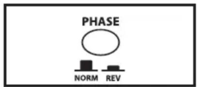
- When the PHASE switch is engaged, the input polarity is reversed so that the instrument and speaker system will not be in Phase and the chance of feedback is reduced.
To adjust the overall system tonal response, the Acoustic Ribbon series provide a 5-band Graphic Equalizer with 12 dB of cut and boost at 100Hz 315Hz, 1kHz, 3.5kHz and 10kHz. - The Acoustic Ribbon series amplifiers have a rear panel Effects Loop for using external signal processors plus a Direct Output making it easy to interface with the main PA system.
- The Acoustic Ribbon series amplifier cabinets are solidly built with rugged plywood construction, precision tuning and Hartke's world-famous, trademarked Kickback™ enclosure.
Guided Tour - Front Panel
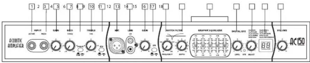
AC75 and AC150 Front Panel
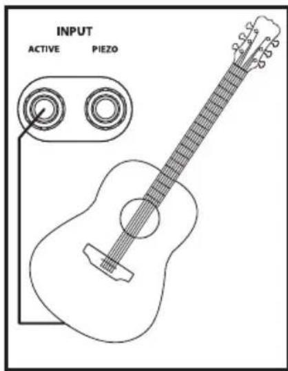
- ACTIVE Input - 1/4-inch phone jack for connecting active inputs. Use this input if your guitar pick-up uses a battery.
- PIEZO (Passive) Input - 1/4-inch phone jack for connecting passive inputs. Use this input if your guitar pick-up does not use a battery.
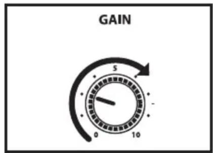
- GAIN (Channel 1) - Control knob is used to control the overall level of the Channel 1 input.
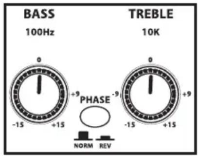
- BASS - Controls the amount of bass, or low frequency, applied to the input connected to channel 1.
- PHASE - Used to reverse the input signal polarity.
- TREBLE - Controls the amount of treble, or high frequency, applied to the input connected to channel 1.
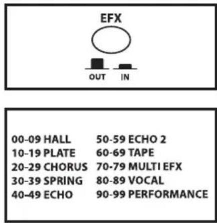
- EFX (Channel 1) - Used to add effects to the signal connected to the Channel 1 input.
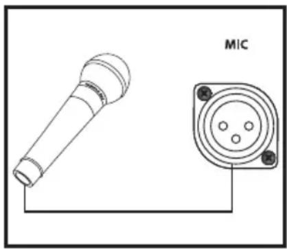
- MIC Input - XLR input connector for connecting to Channel 1's low-noise Microphone Preamp, with Phantom power available for condenser microphones.
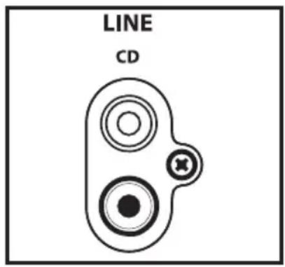
- LINE Input - RCA inputs for connecting an external line level signal like that from a CD, MP3 player or sound card.
- GAIN (Channel 2) - Control knob is used to control the overall level of the Channel 2 input.
- EFX (Channel 2) - Used to add effects to the signal connected to the Channel 2 input.
- FREQUENCY (Notch Filter) - Used to set the center frequency for the Notch Filter.
- DEPTH (Notch Filter) -Control Knob used to control the amount of attenuation applied by the Notch Filter.
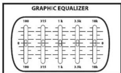
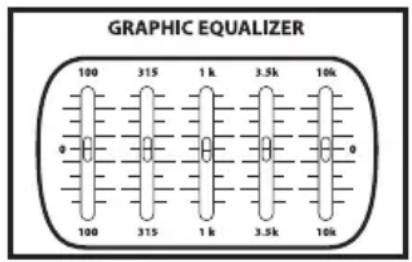
- GRAPHIC EQUALIZER- These sliders allow you to "draw" the tonal response of the system by adding 12 dB of boost or attenuation to seven different narrow-band frequency areas (100Hz, 315Hz, 1kHz, 3.5kHz and 10kHz.) affecting the main output signal of the AC75 or AC150. When a slider is at its center detented ("0") position, the selected frequency area is unaffected (it is said to be flat). When a slider is moved up (above the "0" position, towards the "+" position), the selected frequency area is boosted, and when it is moved down (below the "0" position, towards the "-12" position), the selected frequency area is attenuated. For more information, see the "About Equalization" section on pages 13 - 14 of this manual.
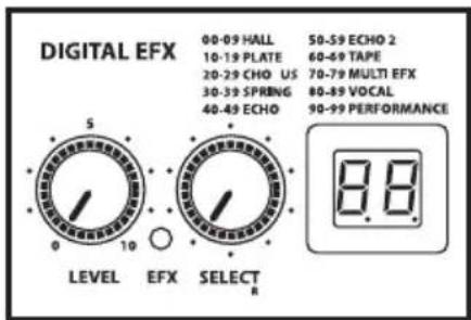
- EFX LEVEL - Control knob used to set the amount of digital effect that's mixed in with the channel input signals.
- EXF SELECT - Used to select one of the available 100 digital effects presets.
- EFX PRESET Display - Shows the current selected preset program number.
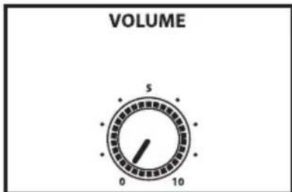
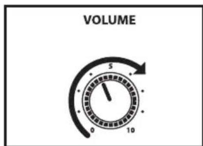
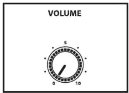
- VOLUME - Control knob used to control the overall level of the AC75 or AC150 amplifier.
Guided Tour - Rear Panel
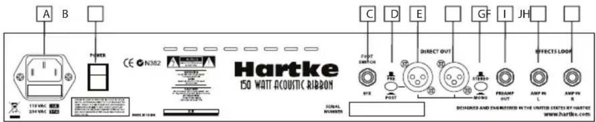
AC150 Rear Panel
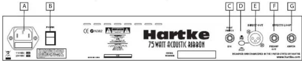
A. AC INLET - Connect the supplied standard IEC power cable here.
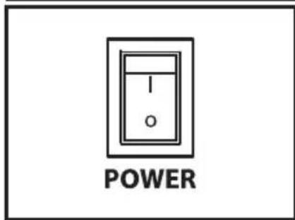
B. POWER SWITCH - Use this to power the AC150 on or off.
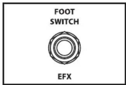
C. FOOTSWITCH Jack - Used with optional footswitch (Hartke part number FS1) to switch the DSP effect on and off.
D. PRE/POST Switch - Used to select the direct output signal from either before or after the channel preamp, equalizer and effects.
E. LEFT DIRECT OUT XLR - This connector carries the Balanced signal from the AC150 main output with the left DSP return and can be used to connect to the main PA mixer. Use the LEFT DIRECT OUT when connecting in MONO.
F. RIGHT DIRECT OUT XLR - This connector carries the Balanced signal from the AC150's main output with the right DSP output and can be used to connect to the main PA mixer.
G. STEREO/MONO switch - Used to select the mono or stereo for the Direct Out. Use the LEFT DIRECT OUT (E) when connecting in MONO.
H. PREAMP OUT jack - The signal from the preamp including the equalizer and effects is sent out of this 1/4-inch jack and can be used with the AMP IN jacks as an effects loop.
I. AMP IN LEFT jack: A connection directly into the left side power amplifier that can be used with the PREAMP OUT jack as an effects loop.
J. AMP IN RIGHT jack - A connection directly into the right side power amplifier that can be used with the PREAMP OUT jack as an effects loop.
AC75 Rear Panel
A. AC INLET - Connect the supplied standard IEC power cable here.
B. POWER SWITCH - Use this to power the AC75 on or off.
C. FOOTSWITCH Jack - Used with optional footswitch (Hartke part number FS1) to switch the DSP effect on and off.
D. PRE/POST Switch- Used to select the direct output from either before or after the channel preamp, equalizer and effects.
E. DIRECT OUT XLR - This connector carries the Balanced signal from the AC75's main output and can be used to connect to the main PA mixer.
F. PREAMP OUTjack - The signal from the preamp including the equalizer and effects is sent out of this 1/4-inch jack and can be used with the AMP IN jacks as an effects loop.
G. AMP IN jack: A connection directly into the power amplifier that can be used with the PREAMP OUT jack as an effects loop.
Setting Up and Using Your Hartke AC75 and AC150 Acoustic Amplifier
AC75 and AC150 Basic Operation
Setting up your Hartke AC75 or AC150 Acoustic amplifier is a simple procedure which takes only a few minutes:
- Remove all packing materials (save them in case of need for future service) and decide where the amplifier is to be physically placed. To avoid potential overheating problems, be sure that the rear panel is unobstructed and that there is good ventilation around the entire unit.
- Connect the 3-pin AC plug into any grounded AC socket. Don't turn the amplifier on just yet, though.
- Use standard, shielded music instrument cable to connect your acoustic guitar, or other electric acoustic instrument to the appropriate Channel 1 Input jack on the front panel. If your acoustic instrument's pick-up system uses a battery connect to the ACTIVE input. If your acoustic instrument does not have a battery, use the PIEZO or passive input.
- Before we turn up the volume, let's set the Acoustic Ribbon controls to the default setting for getting good sound quickly. On Channel 1, set the GAIN knob to "3" (the nine o'clock position) and set BASS and TREBLE controls to "0" (the twelve o'clock position). On Channel 2, set the GAIN knob to "0" (fully counterclockwise position). Set the main VOLUME control to "0" (fully counterclockwise).
- Next, set the Graphic Equalizer sliders to the middle, 0dB position for a flat frequency response.
- Press the front panel Power switch in order to turn on the amplifier.
- Now, let's get some level from the instrument connected to Channel 1. Set the output of your acoustic to about 3/4 's the way up and then, while playing, slowly turn the main Volume control up until the desired level is achieved. If you hear distortion even at low amplifier main Volume settings, back off the output of your Acoustic (or check for a faulty cable).
Note: As a "rule of thumb", always try to keep the main VOLUME control to a higher setting the Channel GAIN controls in order to get the cleanest output.
Setting Up and Using Your Hartke AC75 and AC150 Acoustic Amplifier
- Next, experiment with the AC75 or AC150's graphic equalizer. Begin by setting each of the seven sliders to their flat "0" center detented position. Then, move each filter slider in turn as you play your acoustic and listen to the effect on the tone each of the equalizer filters makes. For more information, see the "About Equalization" section on pages 13-14 of this manual. Again, when you get a graphic equalization setting that complements your instrument and playing style, it's a good idea to write it down for future use.
If you have followed all the steps above and are still experiencing difficulties, call Samson Technical Support (1-800-372-6766) between 9 AM and 5 PM EST.
Using the Channel 1 Tone controls
For enhanced tonal control, Channel 1 features a BASS and TREBLE control. The Bass frequency control has an effect on the low-end frequencies around 100Hz and the TREBLE control has an effect on the frequencies around 10kHz . Setting the BASS and TREBLE knobs to "0" (twelve o'clock position) produces a flat frequency response. To add more lows to the input connected to Channel 1, raise the BASS control above "0" and to reduce the low frequency response, lower the BASS control to a setting below "0". To add more highs to the input connected to Channel 1, raise the TREBLE control above "0" and to reduce the low frequency response, lower the TREBLE control to a setting below "0".
Using the Phase switch
The PHASE switch is used to switch the polarity of the Acoustic Ribbon's speaker system. The PHASE switch can be used in conjunction with the NOTCH FILTER to remove feedback (see the following section Setting the NOTCH FILTER).
In some instants the speaker system can excite the top of the acoustic guitar and create a resonance that produces feedback. By inverting the PHASE of the speaker system, the chance of producing a resonant frequency the feedback is greatly reduced. If you hear feedback, try engaging the PHASE switch. If feedback continues, try to eliminate it using the NOTCH FILTER.
Setting Up and Using Your Hartke AC75 and AC150 Acoustic Amplifier
Using the Digital Effects
You can add of splash a delay and chorus or gallons of lush reverb to either input channel using one of the Acoustic Ribbon's 100 on-board, 24-bit digital effects. The effects section includes a SELECT control with a bright, dual seven-segment LED display to dial up the effects preset, plus a LEVEL control to adjust the amount of effects you want to hear.
- Assign the effects on Channel 1 by setting the EFX ON/OFF switch to the IN position.
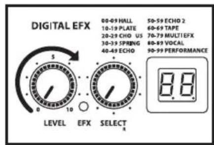
- Next select the desired effect by using the SELECT control. The Effects preset are arranged in logical banks to help you keep organized. Each group includes 10 presets in the following categories; HALL, PLATE, CHORUS, SPRING, ECHO, ECHO2, TAPE, MULTI EFX, VOCAL and PERFORMANCE. You can dial the control clockwise to advance through the effects preset list, or turn it counter-clockwise to descend through the preset list. For this exercise, let use a large room reverb. Use the SELECT control to choose preset number 08.
- Now, slowly raise the effects LEVEL until you add the desired amount of HALL reverb to your acoustic.
- If you want to add the EFX to the MIC or LINE input on Channel 2, engage the EFX ON/OFF switch on Channel 2.
Since the AC150's 5-inch full range speakers are arranged in stereo pairs, you can hear stereo panning on some of the effects. You can find a complete list of the 100 effects presets on page 71 of this manual.
You can also use an optional footswitch, like the Hartke FS1, and the rear panel FOOTSWITCH jack to remotely turn the EFX on and off.
If no footswitch is connected to the FOOTSWITCH jack, the red EFX LED will always illuminate indicating the Digital Effects are on, regardless of the position of the channel EFX switch. The EFX LED will turn off only when the effects are by-passed using the footswitch.
Setting Up and Using Your Hartke AC75 and AC150 Acoustic Amplifier
Using the Mic Input
The AC75 and AC150 Acoustic Ribbon amplifiers offer a microphone input that you can use for mic'ing your acoustic instrument, or for connecting a microphone level signal from an acoustic pre amp like the Hartke Acoustic Attack pedal. You can also use the MIC input to connect a standard low impedance vocal microphone. Plus, the Mic input feature Phantom power for using condenser microphones. The Acoustic Ribbon series amplifiers actually make a great vocal monitor thanks to the flat and natural response of its built-in speaker system.
- If you want to connect a microphone, first start by turning the main VOLUME all the way down. Use a low impedance mic and make the connection with a standard XLR mic cable to the to the Channel 2 XLR mic input located on the front panel.
- Next, raise the main VOLUME to about "6 - 7" (or the 1-to 3 o'clock position).
- Now, slowly raise the GAIN until you add the desired amount of Mic level with your acoustic. Keep in mind that you may need to adjust the Channel 1 and Channel 2 GAIN controls to get the best blend between the mic connected to Channel 2 and the instrument connected to Channel 1.
To add the EFX to the MIC input, engage the EFX ON/OFF switch on Channel 2. The red EFX LED will illuminate when the EFX are engaged.
Setting Up and Using Your Hartke AC75 and AC150 Acoustic Amplifier
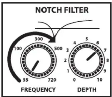
Setting the Notch Filter
The AC75 and AC150's NOTCH FILTER is a powerful tool to help you remove feedback. Feedback is that annoying howling sound that you get when the sound from a loudspeaker is picked up by a microphone connected to the speaker, re-amplified, pick-up again, re-amplified... and so on, so that an acoustical loop is created. The same phenomenon can happen with your electric acoustic since the pick-up system and wood of the instrument become a transducer themselves like a microphone.
The NOTCH FILTER is a "cut only" equalizer that attenuates a narrow band of frequencies. When you set the NOTCH to the feedback frequency, you can cut that frequency to eliminate the feedback. And, since the bandwidth is narrow, the cut has little effect on the tone of your instrument. By using the NOTCH FILTER you can get the maximum level out of your amplifier without feedback.
The NOTCH filter has two controls; FREQUENCY and DEPTH. The FREQUENCY control is used to set the specific frequency that the filter will cut from 55 to 720 Hertz. The DEPTH control is used to set the amount of cut accruing at the FREQUENCY point. The higher the setting, the more cut. Follow the steps below to set-up the NOTCH FILTER
- For our exercise set the NOTCH FILTERS' DEPTH control to "6 - 7".
- With your acoustic instrument connected to the Channel 1 input, try to turn the amplifier up by raising the main VOLUME and the Channel 1 GAIN control to a level right as feedback just occurs.
- Now, turn the NOTCH FILTERS' FREQUENCY knob slowly and stop as soon as you dial in the feedback frequency.
- You may hear the feedback get lower in volume but not go all the way off. If the amplifier still feeds back, increase the DEPTH and repeat the above step. If the amplifier isn't feeding-back and you have enough volume, you're done.
Setting Up and Using Your Hartke AC75 and AC150 Acoustic Amplifier
Using the LINE/CD Input
Your Acoustic Ribbon series amplifier features a LINE/CD input which you can use with a portable CD player, cassette, mini disk or MP3 player to jam with pre-recorded tracks or learn a riff from a favorite tune. In fact, you can plug any line level signal into the LINE input including the signal from a acoustic pre-amp or drum machine. Connect the CD player or other Line level device to the LINE Input using a standard RCA cable.
If you connected a signal to the Channel 2 MIC input, you will want to use the volume control on the CD player or other Line level device to set the balance between the track and your acoustic. So, start with the volume control all the way down and slowly raise it until you reach a good balance with your acoustic
AC75 and AC150 Set-ups
Using the Direct Output
The AC75 feature a Direct Out and the AC150 provide a stereo Direct Out for connecting to the main PA systems. Use these electronically balanced XLR jacks to route signal from the AC75 or AC150 to a recording console or as a tap to a main PA system via a mic input on the main mixer. The signal output from these jack is low impedance (100 ohm) with an output level of approximately -30 to -20 dB. You can also use the Direct Out jack to route signal to an external amplifier with a -10 dB input sensitivity.
By using the PRE/POST switch the Direct Out can send the signal directly from the
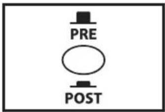
input, or capture the sound of the amp, including the tone controls, equalizer and effects from the AC series preamp.
If you want send the signal of your instrument directly to the PA system, set the PRE/POST switch to PRE. If you want the signal with the sound of the tone controls, equalizer and effects, set the PRE/POST switch to POST.
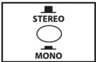
The AC150 there features a LEFT and RIGHT DIRECT OUT. You can use the LEFT and RIGHT DIRECT OUTs to maintain the stereo effects produced by the internal DSP effects. If you want to use the DIRECT OUTS in stereo make sure the STEREO/MONO switch is in the OUT position and connected both the LEFT and RIGHT DIRECT OUTs to two channels of
the main mixer. Be sure to pan the two inputs Left and Right to keep the stereo image. If you want to use the DIRECT OUT to send a mono signal mono make sure the STEREO/MONO switch is set to MONO (in position) and connected the LEFT DIRECT OUT to an input in the main PA.
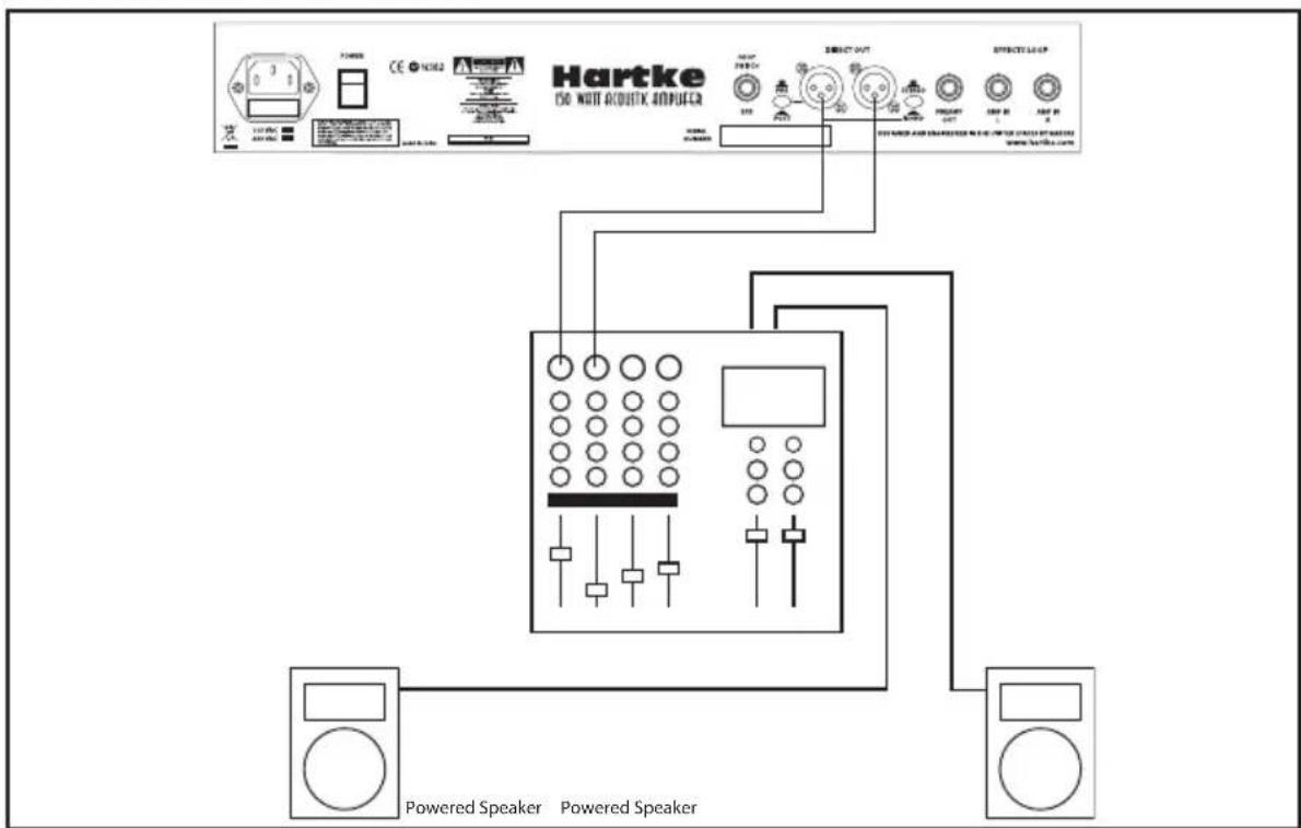
AC150 Stereo Direct Out Hook-up
AC75 and AC150 Set-ups
Using the Effects loop
The AC75 and AC150 Acoustic Ribbon amplifiers feature rear panel PREAMP OUT and AMP IN connectors that access the preamp section and power amp section separately. They can be individual, for example the PREAMP OUT can be used to send the signal to a recorder or AMP IN can be accessed for using the amp as a powered monitor. But, a more common use is as an effects loop for an external processor. If you are using the AC150, the effects can be returned in stereo since the left and right pairs of 5-inch full range speakers are powered by separate 50 watt amplifiers. Therefore, the left side of the effects will be heard in the left pair of 5-inch full range speakers and the right side of the effects will be heard in the right pair of 5-inch full range speakers.
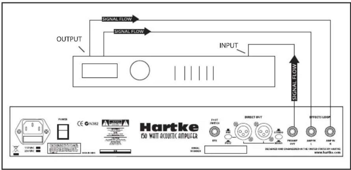
AC150 Stereo Effects Loop Hook-up
- Using a standard shielded instrument cable, connect the AC series rear panel PRE-AMP OUT to the input of your signal processor.
- Now use a standard shielded instrument cable to connect the output of the signal processor to the AC series AMP IN connector located on the rear panel.
- If you are using the AC150 with a stereo effect, you can return both the left and right outputs from the signal processors to the AC150's LEFT and RIGHT AMP IN.
Note: If you are using a delay line effect like a reverb, flanger chorus, digital delay or multi-effects, be sure to pay attention to the effect unit's MIX control so that you have both wet and dry signal. Check the manual of your effects unit to learn how to set the MIX control.
About Equalization
The Hartke AC75 or AC150 Acoustic amplifier gives you enormous control over shaping the sound of your acoustic rig, using a process called equalization. To understand how this works, it's important to know that every naturally occurring sound consists of a broad range of pitches, or frequencies, combined together in a unique way. This blend is what gives every sound its distinctive tonal color. EQ controls allow you to alter a sound by boosting or attenuating specific frequency areas—they operate much like the bass and treble controls on your hi-fi amp, but with much greater precision. The AC75 or AC150 provides you with one most effective tool for shaping the overall tone of your Acoustic sound; a Graphic Equalizer providing 12 dB of cut or boost in five narrow frequency bands.
The five-band graphic equalizer provides seven sliders, each corresponding to a single narrow frequency band (100Hz, 315Hz, 1kHz, 3.5kHz and 10kHz.). This allows you to "draw" the desired tonal response of your system. When a slider is in its center position ("0"), it has no effect. When it is moved above center (towards "+"12"), the particular frequency area is being boosted; when it is moved below center (towards "-12"), the frequency area is being attenuated. We carefully selected these frequency areas because they have maximum impact on acoustic signals. For example, the lowest slider (100 Hz) affects the very lowest audible frequencies (in fact, most humans cannot hear below 20 Hz), while the highest four sliders affects the mid-range and high frequencies.
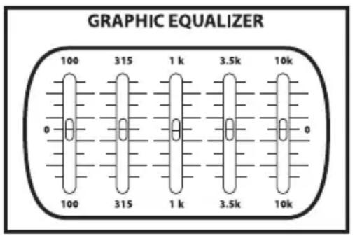
To find out how each graphic equalizer slider affects the sound of your particular acoustic, start with all five bands flat (that is, all five sliders at their "0" center position).
About Equalization
Then, one by one, raise and lower each slider, listening carefully to the effect of each. Note that turning all EQ controls up the same amount will have virtually the same effect as simply turning up the main Volume; conversely, turning them all down the same amount will have virtually the same effect as turning down the main Volume. Both approaches are pointless (after all, that's why we gave you a main Volume control!)
In many instances, the best way to deal with equalization is to think in terms of which frequency areas you need to attenuate, as opposed to which ones you need to boost. Be aware that boosting a frequency area also has the effect of boosting the overall signal; specifically, too much low frequency EQ boost can actually cause overload distortion or even harm a connected speaker.
The specific EQ you will apply to your Acoustic signal is very much dependent upon your particular instrument and personal taste and playing style. However, here are a few general suggestions:
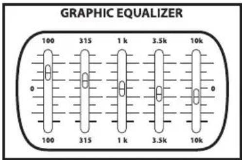
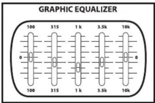
- For that super-warm or mellow sound, boost low frequencies slightly while attenuating the highest ones (leave mid-range frequencies flat or slightly attenuated), as shown in the illustration on the right.
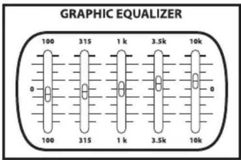
To remove boxiness and make your instrument sound more "hi-fi," try attenuating mid-range frequencies while leaving low and high frequency settings flat, as shown in the illustration on the right. - For a bright, cutting sound, try boosting the high and high mid-range frequencies, as shown in the illustration on the right.
- Whenever you get a really good EQ setting for a particular instrument or song, write it down (you'd be amazed how easy it is to forget these things!).
- Finally, as you experiment with the EQ controls of the AC75 or AC150, don't forget that your acoustic probably provides EQ control, so experiment by using both.
Introduction
AC75 and AC150 Effects Presets
00 Medium Bright Plate.che
01 Best Plate .che
02 Medium Dark Spring.che
03 Short Plate.che
04 Long Bright Spring.che
05 slapback 2.che
06 slapback w verb.che
07 Echo-Verb echo long verb.che
08 slow st chor.che
09 Hall Best Hall 2.che
10 Hall Short Hall.che
11 Hall Short Dark Hall.che
12 Hall Short Bright Hall.che
13 Hall Medium Hall.che
14 Hall Medium Dark Hall.che
15 Hall Medium Bright Hall.che
16 Hall Long Hall.che
17 Hall Long Dark Hall.che
18 Hall Long Bright Hall.che
19 Hall Best Hall.che
20 Short Plate.che
21 Short Dark Plate.che
22 Short Bright Plate.che
23 Plate Long Brite Plate.che
24 Medium Dark Plate.che
25 Medium Bright Plate.che
26 med plate.che
27 Long Plate.che
28 Long Dark Plate.che
29 Best Plate .che
30 Short Spring.che
31 Short Dark Spring.che
32 Short Bright Spring.che
33 Medium Spring.che
34 Medium Dark Spring.che
35 Medium Bright Spring.che
36 Long Spring.che
37 Long Dark Spring.che
38 Long Bright Spring.che
39 Best Spring.che
40 slapback 2.che
41 short echo.che
42 420mS Delay high Feedback.che
43 420mS Delay low Feedback.che
44 550-275mS Delay cross Feedback.che
45 550mS Delay high Feedback.che
46 550mS Delay low Feedback.che
47 650-325mS Delay cross Feedback.che
48 650mS Delay high Feedback.che
49 650mS Delay low Feedback.che
50 flanger-reverb.che
51 flanger-short reverb.che
52 It flanger-med reverb.che
53 med flanger-med reverb.che
54 slo flanger-long reverb.che
55 flanger-long reverb.che
56 stereo flanger-med reverb.che
57 stereo flanger-long reverb.che
58 whip flanger-short reverb.che
59 whip flanger-long reverb.che
60 slow chor short reverb.che
61 slow chor med reverb.che
62 slow chor long reverb.che
63 med chor med reverb.che
64 med chor long reverb.che
65 fast chor short reverb.che
66 fast chor long reverb.che
67 trem chor med reverb.che
68 trem chor long reverb.che
69 big chor med reverb.che
70 Echo-Verb 1.che
71 Echo-Verb hard echo med verb.che
72 Echo-Verb 2.che
73 Echo-Verb 4.che
74 Echo-Verb 3.che
75 pre delay serial.che
76 cross echo.che
77 Echo-Verb echo long verb.che
78 Echo-cross verb.che
79 echoverb.che
80 Chorus 1.che
81 Chorus 2.che
82 Chorus fast.che
83 deep slo chor.che
84 deep fast chor.che
85 med slo chor.che
86 slow st chor.che
87 leslie.che
88 med leslie.che
89 stchor.che
90 slo lt flange.che
91 It flange.che
92 deep slo flange.che
93 deep lt flange.ch
94 deep lazer flange.che
95 jet flange.che
96 jet flange 2.che
97 med flange.che
98 med lazer flange.che
99 strong flange.che
AC75 and AC150 Specifications
Nominal Input Level
Active
Piezo
Mic Input (CH2) -50 dBu.
Line Inputs (CH2) -20 dBu
Rated Output Power
AC75 75 watts (1 x 50 Low Freq. 1 x 25 High Freq)
AC150 150 watts (2 x 50 Low Freq. 1 x 50 High Freq)
Equalizer
Five-Band Graphic (Main Output) ±12 dB, center @ 100 Hz, 350 Hz, 1 kHz, 3.5 kHz, 10 kHz
Connectors
Ch1 Active Input 1 / 4'' phone
Ch1 Piezo Input 1 / 4'' phone
Ch2 Mic Input Female XLR
Ch2 CD In Left and Right RCA
Headphone - St.
Direct Output
TRS 1 / 4'' phone
Male XLR
Speaker System Impedance (Ohms)
Low Frequency Drivers
AC75
4 Ohms Impedance
2 × 5 Special Design Hartke full range 8 ohm, 25 watt Drive Unit
AC150 4× 5 Special Design Hartke full range 8 ohm,25
watt Drive Unit
High Frequency Driver
AC75 2x4-inch planer ribbon on a 5x7 waveguide,
AC150 2 × 4 -inch planer ribbon on a 7 × 7 waveguide.
Dimensions
AC75 Height:17" (43.18 cm) Width:16.5" (42.09 cm)
Depth: 11.25^ (28.30 cm)
AC150 Height:18.85" (47.88 cm) Width:19.75" (50.17 cm)
Depth: 15.25^ (38.48 cm)
Weight
AC75 37.5 lbs. (17 kg)
AC150 48 lbs. (21.8 kg)
Specifications are subject to change without notice.
1 kHz, 3,5 kHz, 10 kHz
Connecteurs
Voie 1 - Entre Active Jack 6,35 mm
Voie 1 - Entre Piezo Jack 6,35 mm
Voie 2 - Entre Mic XLR femelle
Sortie Direct Out XLR male
Tieffrequency-Treiber
AC75 75 watts (1 x 50 Low 1 x 25 High)
AC150 150 watts (2 x 50 Low 1 x 50 High)
Equalizzatore
Grafico a 5-bande (Main Output) ±12 dB, centro @ 100 Hz, 350 Hz, 1 kHz, 3.5 kHz, 10 kHz
Connettori
Ch1 Ingrasso Active
Ch1 Ingrasso Piezo Jack da 1 / 4''
Ch2 CD In Left Right RCA
Cuffie - St.
Direct Out
Jack da 1 / 4''
Jack TRS da 1/4"
XLR maschio
Impedenza del sistema altoparlanti (Ohms) Drivers Basse Frenquence
AC75