
Punch P1692S - Speaker Rockford Fosgate - Free user manual and instructions
Find the device manual for free Punch P1692S Rockford Fosgate in PDF.
| Technical Specifications | 6x9 inch coaxial speaker, maximum power of 400 Watts, RMS power of 100 Watts, impedance of 4 Ohms, frequency response from 45 Hz to 20 kHz, sensitivity of 92 dB. |
|---|---|
| Usage | Ideal for installation in vehicles, enhances audio quality with deep bass and clear highs. |
| Maintenance and Repair | Regularly clean the grills and membranes with a soft cloth, avoid exposure to excessive moisture. |
| Safety | Do not exceed the recommended maximum power to avoid damaging the speaker, use appropriate cables for installation. |
| General Information | Reputable brand in the audio field, limited warranty, compatible with most car stereos. |
Frequently Asked Questions - Punch P1692S Rockford Fosgate
User questions about Punch P1692S Rockford Fosgate
0 question about this device. Answer the ones you know or ask your own.
Ask a new question about this device
Download the instructions for your Speaker in PDF format for free! Find your manual Punch P1692S - Rockford Fosgate and take your electronic device back in hand. On this page are published all the documents necessary for the use of your device. Punch P1692S by Rockford Fosgate.
USER MANUAL Punch P1692S Rockford Fosgate
Installation & Operation
Congratulations on your purchase of the world's finest brand of car audio speakers. At Rockford Fosgate we are fanatics about musical reproduction at its best, and we are pleased you chose our product. Through years of engineering expertise, hand craftsmanship and critical testing procedures, we have created a wide range of products that reproduce music with all the clarity and richness you deserve.
For maximum performance we recommend you have your new Rockford Fosgate product installed by an Authorized Rockford Fosgate Dealer, as we provide specialized training through Rockford Technical Training Institute (RTTI). Please read your warranty and retain your receipt and original carton for possible future use.
Great product and competent installations are only a piece of the puzzle when it comes to your system. Make sure that your installer is using 100% authentic installation accessories from Connecting Punch in your installation. Connecting Punch has everything from RCA cables and speaker wire to Power line and battery connectors. Insist on it! After all, your new system deserves nothing but the best.
To add the finishing touch to your new Rockford Fosgate image order your Rockford accessories, which include everything from T-shirts and jackets to hats and sunglasses.
To get a free brochure on Rockford Fosgate products and Rockford accessories, visit our web site at: www.rockfordfosgate.com or, in the U.S. call 1-800-669-9899 or FAX 1-800-398-3985. For all other countries, call +001-480-967-3565 or FAX +001-480-967-8132.
PRACTICE SAFE SOUND™
Continuous exposure to sound pressure levels over 100dB may cause permanent hearing loss. High powered auto sound systems may produce sound pressure levels well over 130dB. Use common sense and practice safe sound.
If, after reading your manual, you still have questions regarding this product, we recommend that you see your Rockford Fosgate dealer. If you need further assistance, you can call us direct at 1-800-669-9899. Be sure to have your serial number, model number and date of purchase available when you call.
The serial number can be found on the outside of the box. Please record it in the space provided below as your permanent record. This will serve as verification of your factory warranty and may become useful in recovering your unit if it is ever stolen.
Serial Number:
Model Number:
TABLE OF CONTENTS
Introduction. 2
Safety Instructions 3
What This Manual Covers 3
Installation 4-5
Installation Considerations 4
Mounting 4
Installation - Tweeters 5-6
Installation - Speakers 6-7
Troubleshooting. 8
Specifications 8-10
Limited Warranty Information 11
International Instructions. 12
NOTE: Review each section for more detailed information.
GETTING STARTED
Welcome to Rockford Fosgate! This manual is designed to provide information for the owner, salesperson and installer. For those of you who want quick information on how to install this product, please turn to the Installation Section of this manual. Other information can be located by using the Table of Contents. We, at Rockford Fosgate, have worked very hard to make sure all the information in this manual is current. But, as we are constantly finding new ways to improve our product, this information is subject to change without notice.
SAFETY INSTRUCTIONS
WARNING
This symbol with "WARNING" is intended to alert the user to the presence of important instructions. Failure to heed the instructions will result in severe injury or death.
CAUTION
This symbol with "CAUTION" is intended to alert the user to the presence of important instructions. Failure to heed the instructions can result in injury or unit damage.
CAUTION:To prevent injury and damage to the unit, please read and follow the instructions in this manual. We want you to enjoy this system, not get a headache.
CAUTION If you feel unsure about installing this system yourself, have it installed by a qualified Rockford Fosgate technician.
CAUTION Before installation, disconnect the battery negative (-) terminal to prevent damage to the unit, fire and/or possible injury.
INSTALLATION CONSIDERATIONS
The following is a list of tools needed for installation:
Volt/Ohm Meter
2 Phillips screwdriver
Battery post wrench
Hand held drill w/assorted bits
1/8" diameter heatshrink tubing
Wire strippers
Wire crimpers
Wire cutters

CAUTION: If you feel unsure about installing this system yourself, have it installed by a qualified Rockford Fosgate technician.

CAUTION: Before installation, disconnect the battery negative (-) terminal to prevent damage to the unit, fire and/or possible injury.
Before beginning any installation, follow these simple rules:
- Be sure to carefully read and understand the instructions before attempting to install the Unit.
- For safety, disconnect the negative lead from the battery prior to beginning the installation.
- For easier assembly, we suggest you run all wires prior to mounting your unit in place.
- Use high quality connectors for a reliable installation and to minimize signal or power loss.
- Think before you drill! Be careful not to cut or drill into gas tanks, fuel lines, brake or hydraulic lines, vacuum lines or electrical wiring when working on any vehicle.
- Never run wires underneath the vehicle. Running the wires inside the vehicle provides the best protection.
- Avoid running wires over or through sharp edges. Use rubber or plastic grommets to protect any wires routed through metal, especially the firewall.
- Mount the speakers/crossovers away from electrical sources (other than the amplifier) i.e., power cables, electronic fuel pumps, vehicle computers, and other potential noise sources.
- Mount the speakers/crossovers away from areas of extreme heat or moisture.
MOUNTING
Speakers/Tweeters
- Determine where the speakers will be mounted. Ensure an area large enough for the speaker to mount evenly. Be sure that the mounting location is deep enough for the speaker to fit; if mounting in a door, operate all functions (windows, locks, etc.) through their entire operating range to ensure there is no obstruction.
- When mounting the speaker(s) on the rear deck of the vehicle, check the operation of the rear hatch or trunk lid. Make sure the torsion bars and other moving parts are not obstructed by the speaker(s) installation.
- Refer to the specification chart to determine the proper diameter hole to cut for your speaker model.
Crossovers
- Make sure there is a flat area large enough for the crossover to mount.
- For best results, mount the crossover(s) next to the amplifier for a decorative finish to the installation and provide an easy upgrade (no new wires to run) for a bi-amp Rockford Fosgate system in the future.
Use this section when installing Tweeters or Systems
A solid front stage with a good image is one of the most difficult tasks to achieve in a vehicle. No car has the optimum listening environment. This makes proper sound staging very difficult to accomplish. Most speakers tend to be placed where they will fit easily, as opposed to where they can perform the best. The mounting location of your speakers will have a great effect on the sound quality of your stereo system. The special care taken to place the speakers will yield many hours of listening enjoyment in return. Several important recommendations should be followed.
- Place the speakers where they have a direct path to the listening area.
- For the best integration between the midrange and tweeter, the tweeter should be placed less than 2^ from the midrange (Figure 1).
- If you cannot place the tweeter less than 2'' from the midrange, then place the tweeter more than 7'' from the midrange. Placing the tweeter 2'' - 7'' from the midrange can cause destructive interference (frequency response problems) which will affect the speaker's ability to reproduce the frequency range around the crossover frequency of the system.
- Whenever possible, place the tweeter directly above or below the midrange as this maximizes the imaging (point source) capability of the speakers (Figure 1).
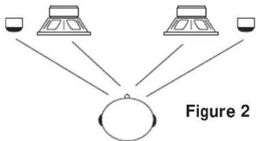
- Sound radiated from a "point source" provides the best stereo imaging because the separation of the acoustical centers between the midrange and tweeter for each channel is at the optimum distance. In a closed environment such as an automobile, horizontal speaker
alignment (Figure 2) can cause amplitude and phase differences which will degrade not only the imaging, but also the frequency response. This is due to the path length differences between the midrange and tweeter. Mounting the speaker with minimum path length difference will ensure the best staging and imaging possible from your audio system.
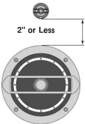
Figure 1
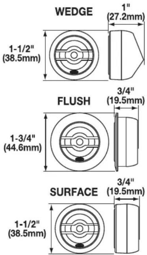
Flush Mount
Top Housing
Tweeter
Bottom Housing
Clip
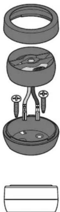
Surface Mount
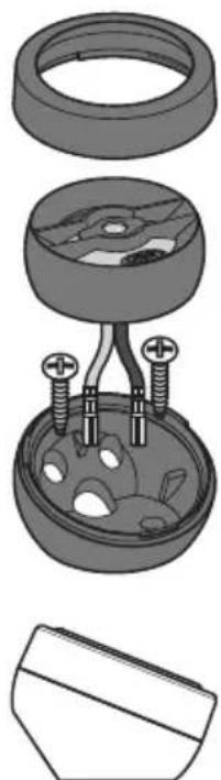
Top Housing
Tweeter
Bottom Housing
Wedge Mount
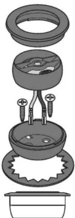
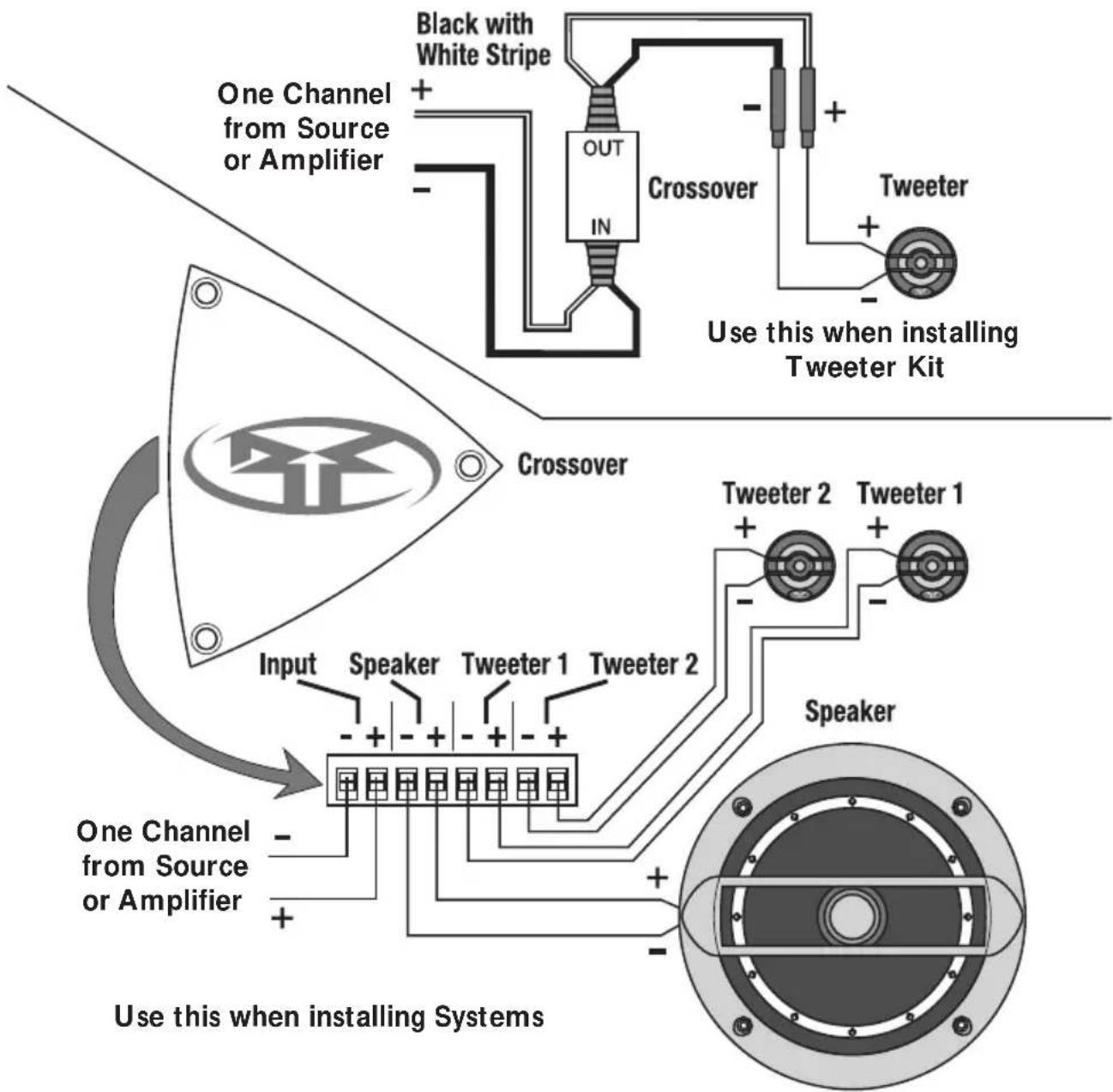
Wiring Tweeter to Crossover
- Use illustrations for proper connection.
- Be sure to maintain speaker polarity
- Cut the proper size hole for the speaker.
NOTE: See Specifications for proper hole size. - Place the mounting ring over the mounting hole and mark the location of the screw mounting holes.
- Remove the ring. Drill the holes for the screws using a 1/8 drill bit.
- Route the wire through the mounting hole cut-out.
- Attach the wires. Observe proper speaker polarity.
- Place the mounting ring over the speaker.
- Place the speaker into the hole and screw the speaker into place.
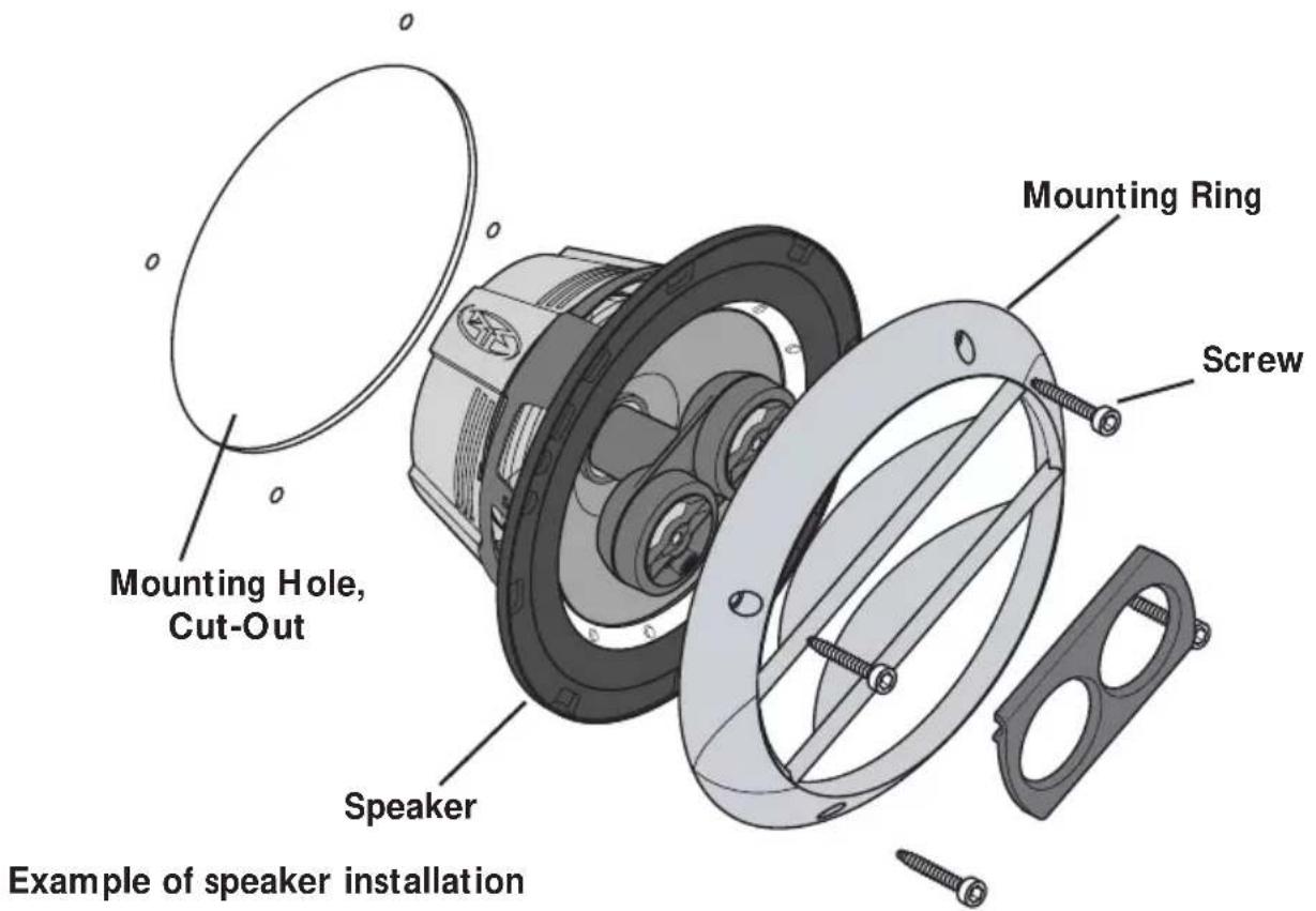

Example of assembly configurations
| Symptom Diagnosis No sound from speakers | Remedy Wires not connected properly. Amplifier has no output. Speaker wires are shorted to each other or to the chassis of vehicle. Speakers are blown. | Check wiring, repair or replace. Check with working amplifier and re- pair or replace as needed. Check wiring with a volt/ohm meter and repair or replace as needed Check with working speaker and repair or replace as needed. |
| Distorted sound from speakers | Incorrect wiring between crossover and speakers | Check wiring, repair or replace. |
| Tweeters "burn up" easily | Excessive power from amplifier Equalizer (if available) has excessive boost in the high frequency range | Check gain settings on amplifier and readjust as necessary Check settings on equalizer and readjust as necessary |
| Engine noise from one or more speakers | Wires shorted to chassis of vehicle. Speaker wires are routed near high power source. (Power cables, vehicle computers, etc.) Crossover is mounted near high power source. | Check wiring with a volt/ohm meter and repair or replace as needed Re-route speaker wiring away from noise sources. Move crossovers away from noise sources. |
SPECIFICATIONS
FEATURES - Tweeters
- Inverted Aluminum Dome
- Multiple Mounting Applications
Nominal Diameter - inch (mm) 3/4 (19mm)
Nominal Impedance (ohms) 4
Frequency Response 4kHz-24kHz
Sensitivity (SPL@1w/1m) 90dB
Power Handling (Watts RMS/Peak) 60 / 120
(with supplied crossover)
Specifications subject to change without notice
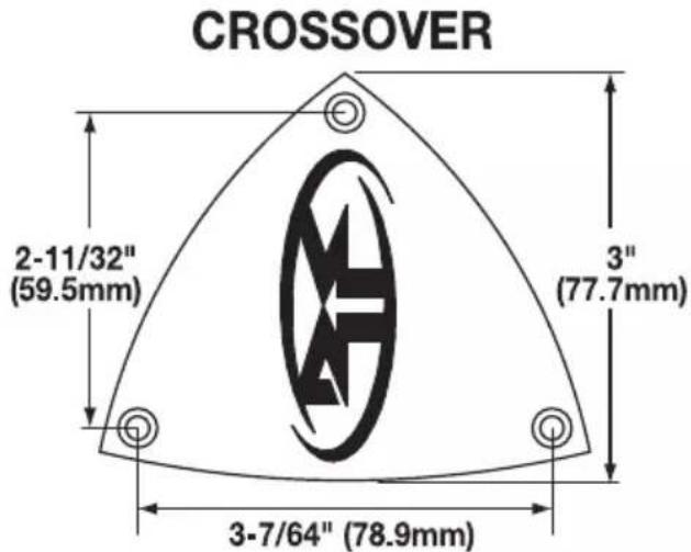
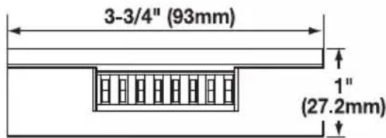
System Crossover DimensionsFEATURES
Crossover Frequency 3200Hz @ 4 Ω
Crossover Slope 12dB/octave High-Pass
12dB/octave Low-Pass
Filter Q Butterworth Tweeter Protection Optical Compression
FEATURES
- Mica Injected Polypropylene Cone
Cold Rolled Vented Steel Frame - Polyurethane Surround
- Multiple Tweeter Mounting Configurations
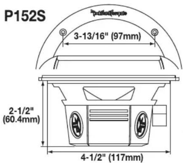
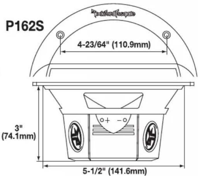
System Model P152S P162S
Nominal Diameter - inch (mm) 5-1/4 (133) 6-1/2 (165)
Nominal Impedance (ohms) 4 4
Frequency Response 70Hz-22kHz
Sensitivity (SPL@1w/1m) 86dB
Power Handling(Watts RMS/Peak)
Mounting Diameter - inch (mm) 4-1/2 (117)
Mounting Depth - inch (mm) 2-1/2 (50.4)
Ω 60Hz-22kHz 88dB
60/120 60/120
4-1/2 (117) 5-1/2 (141.6)
2-1/2 (50.4) 3 (74.1)
Specifications subject to change without notice
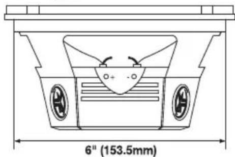
System Model P1682S P1692S
Nominal Diameter - inch (mm) 6 × 8 (152.4 x 203.2) 6 × 9 (152.4 x 228.6)
Nominal Impedance (ohms) 4 4


Frequency Response 60Hz-22kHz
Sensitivity (SPL@1w/1m) 88dB 90dB
Power Handling(Watts RMS/Peak) 60 / 120 60 / 120
Mounting Diameter - inch 5 x 7-1/4
$$ 6 \times 8 - 3 / 4 $$
Mounting Diameter - mm 128.5 x 185
$$ 1 5 3. 5 \times 2 1 9. 5 $$
Mounting Depth - inch (mm)
2-3/4 (72.7) 3 (76)
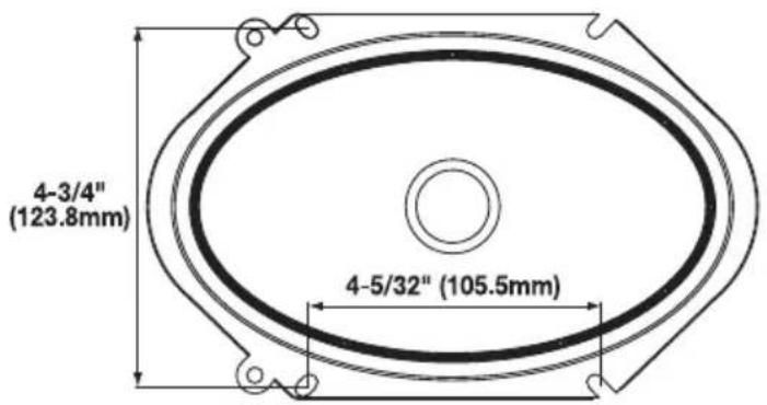
P1682S
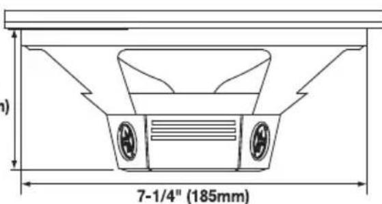
2-3/4" (72.7mm)
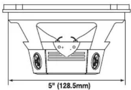
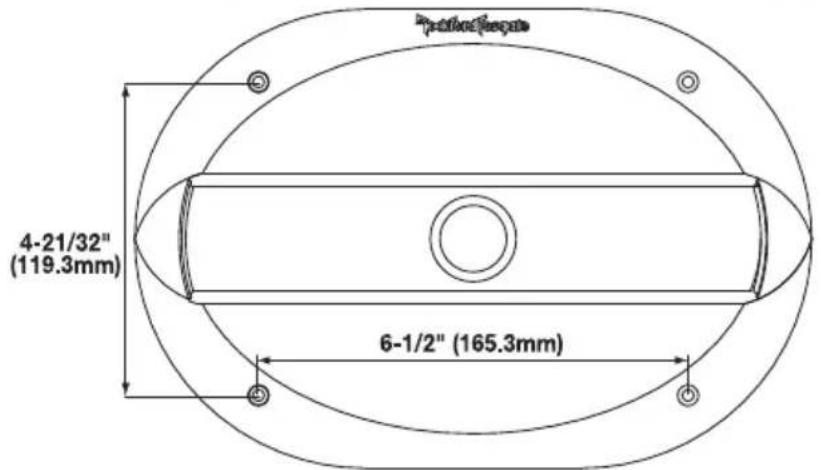
P1692S
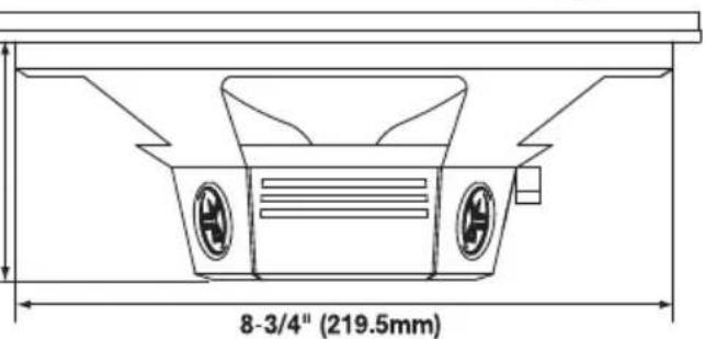
3" (76mm)
Specifications subject to change without notice
Rockford Corporation offers a limited warranty on Rockford Fosgate products on the following terms:
Length of Warranty
Source Units, Speakers, Signal Processors and PUNCH Amplifiers - 1 Year POWER Amplifiers - 2 Years Type RF Amplifiers - 3 Years Any Factory Refurbished Product - 90 days (receipt required)
What is Covered
This warranty applies only to Rockford Fosgate products sold to consumers by Authorized Rockford Fosgate Dealers in the United States of America or its possessions. Product purchased by consumers from an Authorized Rockford Fosgate Dealer in another country are covered only by that country's Distributor and not by Rockford Corporation.
Who is Covered
This warranty covers only the original purchaser of Rockford product purchased from an Authorized Rockford Fosgate Dealer in the United States. In order to receive service, the purchaser must provide Rockford with a copy of the receipt stating the customer name, dealer name, product purchased and date of purchase.
Products found to be defective during the warranty period will be repaired or replaced (with a product deemed to be equivalent) at Rockford's discretion.
What is Not Covered
- Damage caused by accident, abuse, improper operations, water, theft, shipping
2.Any cost or expense related to the removal or reinstallation of product - Service performed by anyone other than Rockford or an Authorized Rockford Fosgate Service Center
4.Any product which has had the serial number defaced,altered, or removed - Subsequent damage to other components
6.Any product purchased outside the U.S.
7.Any product not purchased from an Authorized Rockford Fosgate Dealer
Limit on Implied Warranties
Any implied warranties including warranties of fitness for use and merchantability are limited in duration to the period of the express warranty set forth above. Some states do not allow limitations on the length of an implied warranty, so this limitation may not apply. No person is authorized to assume for Rockford Fosgate any other liability in connection with the sale of the product.
How to Obtain Service
Contact the Authorized Rockford Fosgate Dealer you purchased this product from.
If you need further assistance, call 1-800-669-9899 for Rockford Customer Service. You must obtain an RA# (Return Authorization number) to return any product to Rockford Fosgate. You are responsible for shipment of product to Rockford.
EU Warranty
This product meets the current EU warranty requirements, see your Authorized dealer for details.
Ship to: Electronics
Rockford Corporation
Warranty Repair Department
2055 E. 5th Street
Tempe,AZ 85281
RA#:
Ship to: Speakers
Rockford Acoustic Design
Speaker Returns
2356 Turner Ave. NW
Grand Rapids, MI 49544
RA#:
Cher client,
Rockford Corporation
Warranty Repair Department
2055 E. 5th Street
Tempe,AZ 85281
N°ARM:
Destinataire:Speakers
Rockford Acoustic Design
Speaker Returns
2356 Turner Ave. NW
Grand Rapids, MI 49544
N°ARM
Estimado Cuestione:
Rockford Corporation
Warranty Repair Department
2055 E. 5th Street
Tempe,AZ 85281
RA#:
Enviar a: Speakers
Rockford Acoustic Design
Speaker Returns
2356 Turner Ave. NW
Grand Rapids, MI 49544
RA#:
Senden an: Electronics
Rockford Corporation
Warranty Repair Department
2055 E. 5th Street
Tempe,AZ 85281
RA#:
Senden an: Speakers
Rockford Acoustic Design
Speaker Returns
2356 Turner Ave. NW
Grand Rapids, MI 49544
RA#:
Egregio cliente,
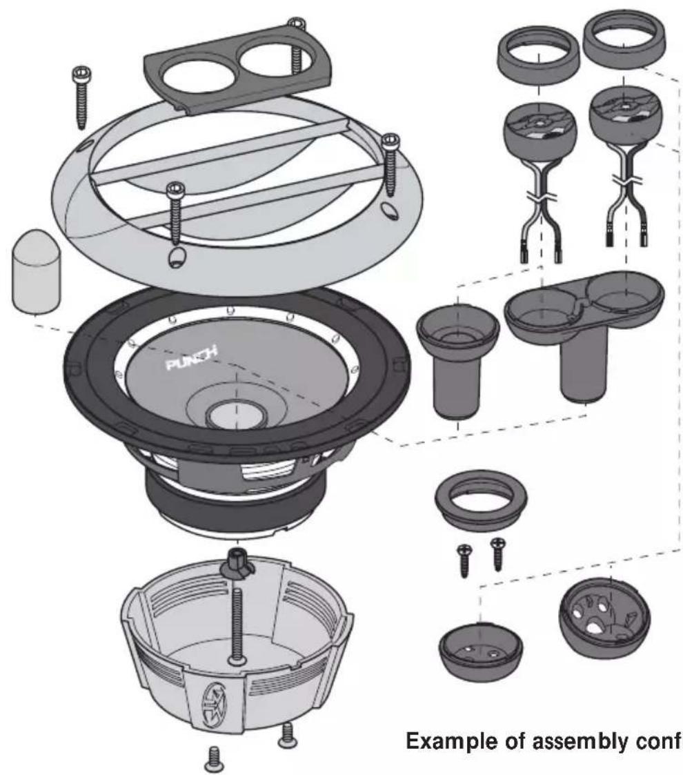
Example of assembly configurations
Rockford Corporation
Warranty Repair Department
2055 E. 5th Street
Tempe,AZ 85281
RA#:
Spedire a: Speakers
Rockford Acoustic Design
Speaker Returns
2356 Turner Ave. NW
Grand Rapids, MI 49544
RA#:
Rockford Fosqate®
Installation assistance available at:
RFTECH
www.rockfordfogate.com/rttech

Rockford Fosgate
Rockford Corporation
546 South Rockford Drive
Tempe,Arizona 85281 U.S.A.
In U.S.A., (480) 967-3565
In Europe, Fax (49) 8503-934014
In Japan, Fax (81) 559-79-1265
www.rockfordfosgate.com