
CTE351 - Printer CITIZEN - Free user manual and instructions
Find the device manual for free CTE351 CITIZEN in PDF.

| Product Type | Thermal line printer |
| Brand | Citizen |
| Model | CTE351 |
| Dimensions (W × D × H) | 125 × 165 × 108 mm |
| Weight | Approx. 1.3 kg |
| Power Supply | AC adapter 37AD5, input 100-240 V AC, 50/60 Hz, output 24 V DC, 2.1 A |
| Printing Method | Thermal line dot matrix |
| Print Width | 72 mm (default), supports 80 mm and 58 mm rolls |
| Dot Density | 8 × 8 dots/mm (203 dpi) |
| Print Speed | Up to 250 mm/s |
| Font and Number of Columns | Font A: 36 columns (12×24 dots), Font B: 48 columns (9×24), Font C: 54 columns (8×16) |
| Barcode Types | UPC-A/E, JAN(EAN) 13/8, ITF, CODE39, CODE128, CODABAR, CODE93, PDF417, QR Code, GS1-DataBar |
| Interface | USB + serial or Ethernet + USB depending on model |
| Input Buffer | 4 KB / 45 bytes |
| Power Consumption | Approx. 2.0 A (average), 0.1 A (standby) |
| Operating Temperature | 5 to 45 °C, relative humidity 10-90% (non-condensing) |
| Reliability | Head: 150 km or 300 million pulses; Auto cutter: 1.5 million cuts (3") / 1 million (2") |
| Safety Standards | UL, C-UL, FCC Class A, CE marking |
| Main Functions | High-speed printing, compact design, front ejection, auto cutter, Long Life Print, paper saving, kanji and 2D barcode support, USB power off, dual interface, built-in cash drawer |
| Maintenance and Cleaning | Periodically clean the print head and platen with a cotton swab moistened with ethyl alcohol after cooling; do not use organic solvents |
| Safety | Use specified adapter, ground properly, avoid ventilation obstacles, do not open during printing, unplug during thunderstorms |
| Spare Parts and Repairability | Contact Citizen Systems dealer; do not attempt to repair yourself |
Frequently Asked Questions - CTE351 CITIZEN
User questions about CTE351 CITIZEN
0 question about this device. Answer the ones you know or ask your own.
Ask a new question about this device
Download the instructions for your Printer in PDF format for free! Find your manual CTE351 - CITIZEN and take your electronic device back in hand. On this page are published all the documents necessary for the use of your device. CTE351 by CITIZEN.
USER MANUAL CTE351 CITIZEN
LINE THERMAL PRINTER
MODEL CT-E351
User's Manual
Mode d'emploi
Benutzerhandbuch
Manuale dell'utente
Manual de Usuario
natural_image
Line drawing of a rectangular electronic device with a lid and internal panel (no text or symbols)If you want to dispose of this product, do not mix it with general household waste. There is a separate collection systems for used electronics products in accordance with legislation under the WEEE Directive (Directive 2002/96/EC) and is effective only within European Union.

natural_image
Symbol of a trash bin crossed with no visible text or labelsCompliance Statement for European Users
CE marking shows conformity to the following criteria and provisions:
Low Voltage Directive (2014/35/EU), EMC Directive (2014/30/EU), and RoHS directive (2011/65/EU)
Full text of the EU declaration of conformity is available at the following internet address:
http://www.citizen-systems.co.jp/english/support/download/printer/others/eu_doc/
IMPORTANT: This equipment generates, uses, and can radiate radio frequency-energy and if not installed and used in accordance with the instruction manual, may cause interference to radio communications. It has been tested and found to comply with the limits for a Class A computing device pursuant to Subpart J of Part 15 of FCCRules, which are designed to provide reasonable protection against such interference when operated in a commercial environment. Operation of this equipment in a residential area is likely to cause interference, in which case the user at his own expense will be required to take whatever measures may be necessary to correct the interference.
CAUTION: Use shielded cable for this equipment.
Sicherheitshinweis
This Class A Information Technology Equipment (ITE) complies with Canadian CAN ICES-3(A)/NMB-3(A).
This Information Technology Equipment (ITE) does not exceed the Class A limits for radio noise emissions from digital apparatus set out in the Radio Interference Regulations of the Canadian Department of Communications.
- Before using this product, be sure to read through this manual. After having read this manual, keep it in a safe, readily accessible place for future reference.
● The information contained herein is subject to change without prior notice. - Reproduction or transfer of part or all of this document in any means is prohibited without permission from Citizen Systems.
- Note that Citizen Systems is not responsible for any operation results regardless of omissions, errors, or misprints in this manual.
- Note that Citizen Systems is not responsible for any trouble caused as a result of using options or consumables that are not specified in this manual.
- Except explained elsewhere in this manual, do not attempt to service, disassemble, or repair this product.
- Note that Citizen Systems is not responsible for any damage attributable to incorrect operation/handling or improper operating environments that are not specified in this manual.
- Data is basically for temporary use and not stored for an extended period of time or permanently. Please note that Citizen Systems is not responsible for damage or lost profit resulting from the loss of data caused by accidents, repairs, tests or other occurrences.
- If you find omissions, errors, or have questions, please contact your Citizen Systems dealer.
-
If you find any pages missing or out of order, contact your Citizen Systems dealer for a replacement.
-
EPSON and ESC/POS are registered trademarks of Seiko Epson Corporation.
- QR Code is a registered trademark of DENSO WAVE INCORPORATED.
- Ethernet is a registered trademark of Fuji Xerox Corporation.
● CITIZEN is a registered trademark of Citizen Watch Co., Ltd.
● All other trademarks are the property of their respective owners. - Citizen Systems use these trademarks in accordance with the license of relevant owners.
Copyright© CITIZEN SYSTEMS JAPAN CO., LTD. 2017
SAFETY PRECAUTIONS...WHICH SHOULD BE STRICTLY OBSERVED
Before using this product for the first time, carefully read these SAFETY PRECAUTIONS. Improper handling may result in accidents (fire, electric shock or injury). In order to prevent injury to operators, third parties, or damage to property, special warning symbols are used in the User's Manual to indicate important items to be strictly observed.
- After having read this Manual, keep it in a safe, readily accessible place for future reference.
- Some of the descriptions contained in this manual may not be relevant to some printer models.
The following describes the degree of hazard and damage that could occur if the printer is improperly operated by ignoring the instructions indicated by the warning symbols. Be sure to read this information carefully.

WARNING
Neglecting precautions indicated by this symbol may result in fatal or serious injury.

CAUTION
Neglecting precautions indicated by this symbol may result in injury or damage to property.

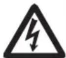
This symbol is used to alert your attention to important items.

This symbol is used to alert you to the danger of electric shock or electrostatic damage.

This symbol denotes a request to unplug the printer from the wall outlet.

This symbol is used to indicate that the power supply must be grounded.

This symbol is used to indicate useful information, such as procedures, instructions or the like.

This symbol is used to indicate prohibited actions.
PRECAUTIONS ON PRINTER INSTALLATION

WARNING
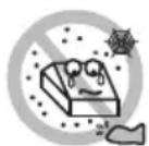
Do not use or store this product in a place where it will be exposed to:
* Flames or moist air.
* Direct sunlight.
* Hot airflow or radiation from a heating device.
* Salty air or corrosive gases.
* Ill-ventilated atmosphere.
* Chemical reactions in a laboratory.
* Airborne oil, steel particles, or dust.
* Static electricity or strong magnetic fields.
- These locations create the risk of printer damage, as well as product failure, overheating, emission of smoke, fire, or electric shock. They can also result in fire or electric shocks and so should always be avoided.

■ Do not drop any foreign object nor spill liquid into the printer. Do not place any object on the printer either.
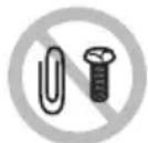
■ Do not drop any metallic object such as paper clips, pins or screws into the printer.
■ Do not place a flower vase, pot, or anything containing water on the printer.
■ Do not spill coffee, soft drinks, or any other liquid into the printer.
■ Do not spray insecticide or any other chemical liquid over the printer.
- Dropping a metallic foreign object into the printer, may cause printer failure, fire, or electric shock.
Should it occur, immediately turn the printer off, unplug it from the supply outlet, and call your local Citizen Systems dealer.


Do not handle the printer in the following ways:
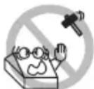
■ Do not subject the printer to strong impacts or hard jolts (e.g., being stepped on, dropped or struck).
■ Never attempt to disassemble or modify the printer.
- These actions create the risk of printer damage, as well as product failure, overheating, emission of smoke, fire, or electric shock.
They can also result in fire or electric shocks and so should always be avoided.

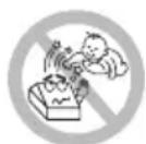
■ This device is not appropriate to be used where a child may be present. Install, store, or use the device where it cannot be reached by a child.
- Electric appliances could cause an unexpected injury or accident if they are handled or used improperly.
- Keep the power cord and signal cables out of the reach of children. Also children should not be allowed to gain access to any internal part of the printer.
- The plastic bag the printer came in must be disposed of properly or kept away from children. Wearing it over the head may lead to suffocation.

CAUTION
Do not use the printer under the following conditions.
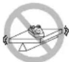
■ Avoid locations subject to vibration or instability.
■ Avoid locations where the printer is not level.
• The printer may fall and cause an injury.
- The quality of printing may deteriorate.
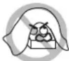
- Do not obstruct the printer's air vents.
■ Do not place anything on the printer.
■ Do not cover or wrap the printer in cloth or blankets.
- Doing so could cause heat to build up and deform the case or start a fire.
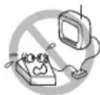
■ Avoid using the printer near a radio or TV set or from supplying it from the same electric outlet as these appliances.
■ Avoid using the printer interconnected with a cable or cord that has no protection against noise.
(For interconnections, use shielded or a twisted pair of cables and ferrite cores, or other anti-noise devices.)
■ Avoid using the printer with a device that is a strong source of noise.
- The printer may have an adverse effect on nearby radio or TV transmissions. There may also be cases when nearby electrical appliances adversely influence the printer, causing data errors or malfunction.
■ Installed in any orientation other than those specified.
- Malfunction, failure, or electric shock may result.
■ Connect the printer to a ground.
• Electric leakage may cause an electric shock.
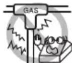
- Do not connect the printer's ground to any of the following:
* Gas piping
• A gas explosion could result.
* Telephone line ground
* Lightning rod
- If lightning strikes a large surge of current may cause fire or shock.
* Water pipes
- Plastic water pipes should not be used for grounding. (Those approved by a Waterworks Department may be used.)
■ Before connecting or disconnecting the grounding lead to or from the printer, always unplug it from the electric outlet.


PRECAUTIONS IN HANDLING THE PRINTER

WARNING
Please observe the following precautions for power source and power cord:
■ Do not plug or unplug the power cord with a wet hand.
■ Use the printer only at the specified supply voltage and frequency.
■ Use only the specified AC adapter with the printer.
■ Use only the power cord that comes with the printer, and never use the supplied power cord with another device.
■ Check to make sure that the supply outlet from which the printer is powered has a sufficient capacity.
■ Do not supply the printer from a power strip or current tap shared with other appliances.
■ Do not plug the power cord into an electric outlet with dust or debris left on the plug.
■ Do not use a deformed or damaged power cord.
■ Do not move the printer while its power is on.
- Neglecting to handle it properly may result in printer failure, emission of smoke, fire, or electric shock.
- An overload may cause the power cord to overheat, catch fire, or the circuit breaker to trip.
■ Do not allow anything to rest on the power cord. Do not place the printer where the power cord may be stepped on.
■ Do not subject the power cord to severe bending, twisting, or pulling. Do not carry the product while it is in this state either.
■ Do not attempt to modify the power cord unnecessarily.
■ Do not place the power cord near any heating device.
- Neglecting these cautions may cause wires or insulation to break, which could result in electric leakage, electric shock, or printer failure. If the power cord sustains damage, contact your Citizen Systems dealer.
■ Do not leave things around the electric outlet.
■ Supply power to the printer from a convenient electric outlet, readily accessible in an emergency.
- Pull the plug to immediately shut it down in an emergency.
■ Insert the power plug fully into the outlet.
■ If the printer will not be used for a long time, disconnect it from its electric outlet.
■ Hold the plug and connector when plugging or unplugging the power cord or signal cable after turning off the printer and the appliance connected to it.


CAUTION
Caution label is attached in the position shown in the following figure. Carefully read the handling precautions before using the printer.
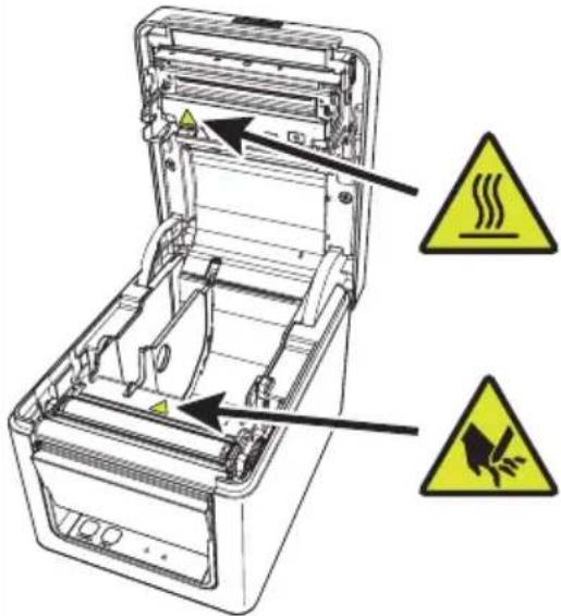
These labels indicate that the head becomes hot, so touching it may cause burns, and touching the auto cutter when opening the paper cover may cause cuts on hands.
Do not transport this printer with the paper roll inside.
- Printer failure or damage may occur.
To prevent possible malfunction or failure observe the following.
■ Do not open the paper cover during printing.
■ Avoid operating the printer without paper properly loaded.
■ Avoid the use of paper not complying with specifications.
- May result in poor print quality.
■ Avoid using torn pieces of paper or paper spliced with plastic adhesive tape.
■ Avoid forcibly pulling already loaded paper by hand.
■ Avoid using a sharp pointed device to operate panel buttons.

Be sure to firmly insert the cable plugs into their mating sockets.
- A cross connection may damage the printer's internal electronics or the host system's hardware.
Only use the printer with devices that have designated solenoid specifications for the cash drawer interface connector.
- Neglecting this caution may result in malfunction or failure.
To prevent injury and printer failures from worsening, observe the following:
■ Do not touch the printing surface of the thermal head.
■ Do not touch any of the moving parts (e.g., paper cutter, gears, active electric parts) while the printer is working.
In case of trouble do not attempt to repair the printer. Ask Citizen Systems service for repair.
■ Be careful that the covers do not pinch your hands or fingers.
■ Be careful of the sharp edges on the printer. Do not allow them to injure you or damage property.
- May result in electric shock, burn, or injury.

If the printer emits smoke, an odd smell, or unusual noise while printing, immediately abort the current print session and unplug the printer from the electric outlet.

DAILY MAINTENANCE
Observe the following precautions for daily maintenance.
■ When cleaning the printer, always turn it off and unplug it from the electric outlet.
■ Use a soft, dry cloth for cleaning the surface of the printer case.
For severe stains, use a soft cloth slightly dampened with water.
Never use organic cleaning solvent such as alcohol, paint thinner, trichloroethylene, benzene, or ketone. Never use a chemically processed cleaning cloth.
■ To remove paper dust, use a soft brush.


CAUTION
The thermal head is at a dangerously high temperature immediately after printing.
Allow it to cool off before starting maintenance work.
THE TABLE OF CONTENTS
1. GENERAL OUTLINE ....13
1.1 Features .... 13
1.2 Unpacking .... 14
1.3 Model Classification ..... 15
1.4 Basic Specifications .... 15
2. EXPLANATION OF PRINTER PARTS......17
2.1 Printer Appearance .... 17
2.2 Inside the Paper Cover....19
2.3 Other Built-in Functions....20
3. SETUP....22
3.1 Connecting the AC Power Cord....22
3.2 Connecting Interface Cables 23
3.3 Ethernet (LAN) Interface 24
3.4 Connecting the Cash Drawer 27
3.5 Precautions for Installing the Printer .....29
3.6 Loading Paper 30
3.7 58-mm Width Roll Paper Partition ....32
3.8 Setting the Long Life Printing (LLP) Function....33
3.9 Precautions for Creating Applications and Practical Operations .....34
3.10 Download Site for Various Electronic Files 34
4. MAINTENANCE AND TROUBLESHOOTING ....35
4.1 Periodic Cleaning 35
4.2 Clearing a Cutter Error 36
4.3 Self Test....37
4.4 Hexadecimal Dump Printing....38
4.5 Error Indications .... 39
4.6 Paper Jams 41
4.7 Precautions for Performing Printing for Which Printing Speed Changes .... 41
5. OTHER 42
5.1 External Views and Dimensions 42
5.2 Printing Paper....43
5.3 Manual Setting of Memory Switches 44
1. GENERAL OUTLINE
The CT-E351 line thermal printer series is designed for use with a broad array of terminal equipment including data, POS, and kitchen terminals.
These printers have extensive features so they can be used in a wide range of applications.
1.1 Features
● High-speed printing at up to 250 mm/sec possible
- Stylish design
- Compact size with the lowest possible height
● The front paper eject structure enables use where the height is restricted
● Compliant with IPX1 for drip-proof capabilities *
● Support for paper widths of 80 mm and 58 mm
● High-speed cutter employed
● Long Life Printing (LLP) function to increase the head life available
● Dual interfaces (USB + serial / Ethernet + USB)
● Built-in drawer kick interface
- USB-linked power OFF function available
● Paper saving function available
● Support for the JIS X0213 third and fourth level Kanji character sets
● Support for the simplified and traditional Chinese character sets and Hangul character set
● Various customizations using the memory switches possible
- User created characters and logos can be saved in the user memory
● Support for barcodes including 2D barcodes
*: The product has been checked to determine that vertically falling drops of water will have no harmful effect, but the product is not guaranteed to be completely drip-proof.
1.2 Unpacking
Make sure the following items are included with your printer.
| NAME | QUANTITY | ILLUSTRATION |
| Printer 1 | 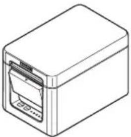 | |
| AC Adapter (37AD5) 1 | 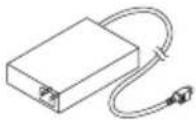 | |
| AC power cord 1 |  | |
| Partition 1 | 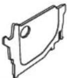 | |
| Cable clamp 1 |  | |
| Sample paper roll 1 roll | 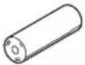 | |
| Quick Start Guide 2 | 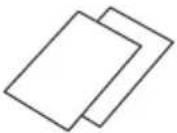 |
1.3 Model Classification
Model numbers indicate printer features according to the following system.

- Model name
- Interface
RS: USB + serial
ET: Ethernet+USB
- Market
U: North America
E: Europe
- Body case color
WH: Pure white
BK: Black
Contact us in advance for special combinations, some of which may not be available.
1.4 Basic Specifications
| Item Specifications | |||
| Model CT-E351 | |||
| Print method Line thermal dot print method | |||
| Print widths 72 mm/576 dots, 68.25 mm/546 dots, 64 mm/512 dots, 52.5 mm/420 dots, 48.75 m/390 dots, 48 mm/384 dots, 45 mm/360 dots, factory default 72 mm | |||
| Dot density 8 × 8 dots/mm (203 dpi) | |||
| Print Speed 250 mm/sec (maximum speed, print density level 100%, 2000 dot lines/sec) | |||
| Number of print columns *1 | Font Maximum number of characters (columns) / 54 mm | Dot configuration (dots) | |
| Font A 36 12 × 24 | |||
| Font B 48 | 9 × 24 | ||
| Font C | 54 | 8 × 16 | |
| Character size *2 | Font A:1.50×3.00 mm, Font B:1.13×3.00 mm, Font C:1.00×2.00 mm | ||
| Character type | Alphanumeric characters, international characters, PC437/850/852/857/858/860/863/864/865/866, WPC1252, Katakana, ThaiCode 11/18 (1Pass/3Pass), TCVN-3, Kanji (JIS first, second, third, and fourth level), Kana, extended characters, JIS X0213, GB18030, BIG5, KS Hangul, EUC Hangul | ||
| User memory | 384 KB (capable of storing user-defined characters and logos) | ||
| Bar code types | UPC-A/E, JAN(EAN) 13 digits/8 digits, ITF, CODE39, CODE128, CODABAR(NW-7), CODE93, PDF417, QR Code, GS1-DataBar | ||
| Item Specifications | |
| Line spacing 4.25 mm (1/6 inch) (Variable by command) | |
| Paper roll Roll paper: 80 | mm x max. ø83 mmPaper thickness: 53 to 85 μm (paper roll inner diameter 12 mm / outer diameter 18 mm) |
| Interface | USB + serial / Ethernet + USB |
| Cash drawer kick-out Supports 2 cash drawers | |
| Input buffer 4 K bytes/45 | bytes |
| Supply voltage DC 24 V | ±5% |
| Power consumption | Approximately 2.0 A (average), approximately 0.1 A (standby) |
| AC Adapter(37AD5) | Rated input: AC 100 to 240 V, 50/60 Hz, 150 VARated output: DC 24 V, 2.1 A |
| Weight Approximately 1.3 kg | |
| Outside dimensions 125 | (W) × 165 (D) × 108 (H) mm |
| Operating temperature and humidity | 5 to 45°C, 10 to 90% RH (no condensation) |
| Storage temperature and humidity | -20 to 60°C, 10 to 90% RH (no condensation) |
| Reliability Print head life: | 150 km, 300 million pulses (room temperature, room humidity, speci-fied recommended paper, specified paper thickness), Auto cutter life: 1.5 million cuts (3-inch), 1 million cuts (2-inch) (room temperature, room humidity, specified recom-mended paper, specified paper thickness) |
| Safety standard *3 UL, C-UL, FCC Class A, CE Marking | |
Notes:
*1: The number of printable columns is selected using a memory switch.
The numbers of columns noted in this table refer to typical models. The number of columns varies depending on specifications.
*2: Characters appear small because the dimensions include a blank area surrounding each character.
*3: This standard applies when our AC Adapter (37AD5) is used.
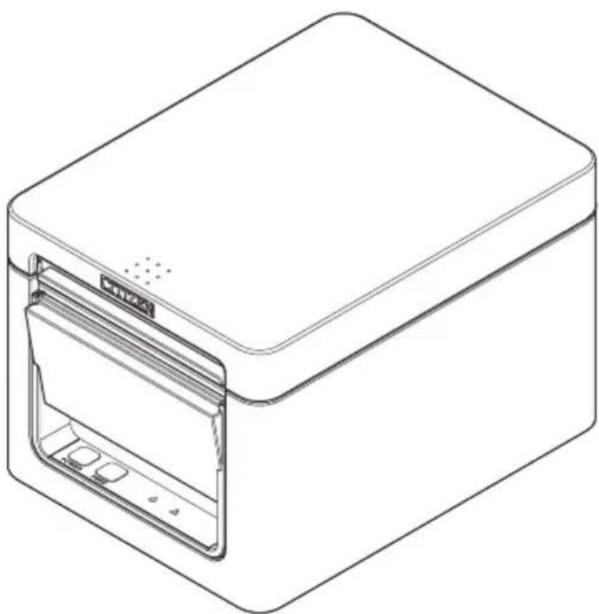
2. EXPLANATION OF PRINTER PARTS
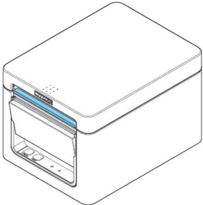
2.1 Printer Appearance
Names of parts
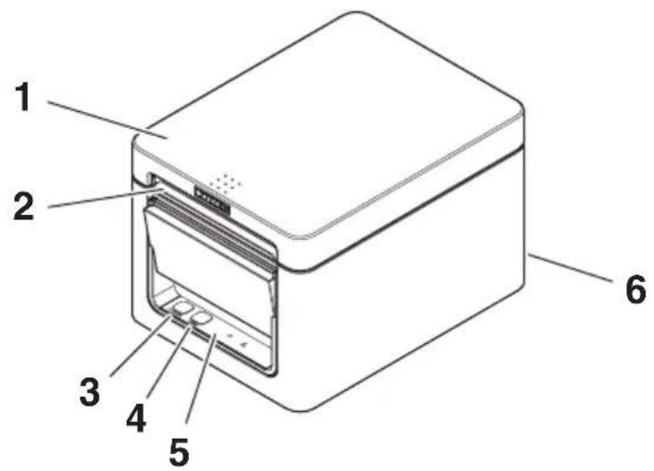
- Paper cover
Open to load paper.
Also open to clear a cutter error.
* The paper cover cannot be used for manual cutting.

Refer to 4.2 Clearing a Cutter Error
- Cover open lever
Use to open the paper cover.
- POWER button
Hold down two or three seconds to switch power on or off.
- FEED button
Press this button to feed paper.
In case of a cutter error, press the FEED button with the paper cover closed after removing the cause.
The printer enters the mode for setting memory switches and running self test.

Refer to 4.3 Self Test

Refer to 5.3 Manual Setting of Memory Switches
-
Operation panel
-
Rear connectors
Operation panel
POWER
FEED


Two LEDs and two keys are placed on the operation panel.
| LED name Description | ||
 | POWER LED | Turns on when the power is turned on and turns off when the power is turned off.Flashes when a memory error occurs and when data is being received. |
 | ERROR LED | Flashes when the print head is hot, when the paper cover is open, when a cutter error occurs, and so on. |

Refer to 4.5 Error Indications
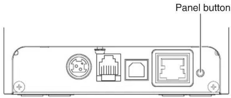
Rear connectors
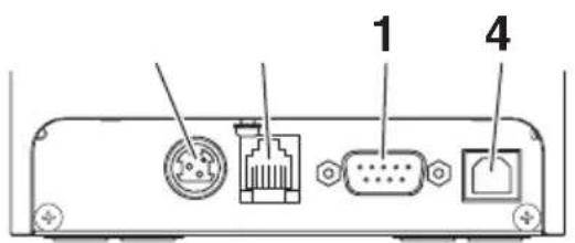
USB + serial
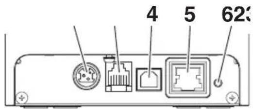
Ethernet + USB
- Serial connector (serial, USB, etc.) Connect to the interface cable.
- Cash drawer kick-out connector Connect to the cable from the cash drawer.
- Power connector Connect to the AC adapter cable.
- USB connector
- Ethernet connector
- Panel button The current configuration information can be printed. For details, refer to "Ethernet (LAN) Interface" in Section 3.3.

Refer to 3.3 Ethernet (LAN) Interface
2.2 Inside the Paper Cover

- Print head (thermal)
Prints characters and graphic data on paper (paper rolls).
- Paper end (PE) sensor
Detects when there is no paper. Printing stops when this sensor detects there is no paper.
- Platen
Feeds the paper.
Do not remove the platen except to do maintenance.
- Auto cutter
Cuts the paper.

Refer to 5.3 Manual Setting of Memory Switches
2.3 Other Built-in Functions
- Buzzer
Buzzes when errors occur or when operations or command operations are performed.

Refer to 4.5 Error Indications
- User memory
You can save user-defined logo and character data in this memory. Data remains stored in this memory even if the printer is turned off. For information on how to save data, refer to the Command Reference.
- Memory switch
Setting of various kinds of functions can be stored in memory. Settings remain stored in the memory even if the printer is turned off.
- USB-linked power OFF (When MSW6-3 of memory switch is set to ON)
When the printer is connected to PC by USB, the printer becomes the state of USB-linked power OFF after 3 seconds when PC power off or USB connection lost.
This mode is canceled when the PC is turned back on or when a USB connection is established.

CAUTION
■ Since the POWER LED is unlit when the state of USB-linked power OFF, it cannot be identified from the power OFF.
- Pressing the POWER button while the state of USB-linked power OFF turns on power normally.
● Paper saving functions
Memory switches MSW8-3 through MSW8-4 can be used to configure the settings below, which save paper.
- Top margin suppression
The printer back feeds the paper before printing which reduces the blank space at the top edge of the paper.
The back feed amount can be specified.
- Line gap reduce
Automatically compresses the linefeed amount between lines. The compression ratio can be specified.

CAUTION
Remove the partially cut paper before performing back feed for starting printing.
The cut paper may be torn off in the next printing process, which may cause a problem.
● Auto side shift (MSW8-6)
This function dissipates heat load during frequent heat generation by a vertical ruled line or other specific head heating element.
If no data is received within 15 seconds after each cut or print, the print position is automatically slid N* dots to the right. The original print position is returned to at the next slide timing.
* N is the MSW8-6 setting value.

CAUTION
If the right margin is too narrow, this may result in some print characters being cut off.
■ This function is disabled under initial settings.
■ To enable this function, use MSW8-6 to specify an appropriate value for the maximum slide amount.
3. SETUP
3.1 Connecting the AC Power Cord
-
Turn off the power.
-
Connect the power connector to the AC adapter cable connector. Next, connect the AC power cord to the AC inlet, and insert the plug into an electric outlet.
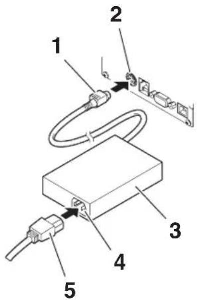
- Cable connector
- Power connector
- AC adapter
- AC inlet
- AC power cord

CAUTION
■ Use only the specified AC adapter.
■ Always hold the AC adapter's cable connector by the connector when removing or inserting it.
■ Use an AC power source that does not also supply power to equipment that generates electromagnetic noise.
■ Pulling on the AC power cord may damage it, cause a fire, electric shock, or break a wire.
If a lightning storm is approaching, unplug the AC power cord from the electric outlet. A lightning strike may cause a fire or electric shock.
- Keep the AC power cord away from heat generating appliances. The insulation on the AC power cord may melt and cause a fire or electric shock.
■ If the printer is not going to be used for a long time, unplug the AC power cord from the electric outlet.
■ Place the AC power cord so that people do not trip on it.
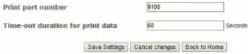
3.2 Connecting Interface Cables
-
Turn off the power.
-
Orient the interface cable correctly and insert it into the interface connector.
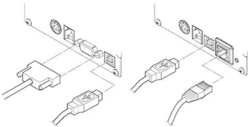
natural_image
Technical line drawing showing two installation or assembly steps of connected electronic components (no text or symbols present)USB + serial Ethernet + USB

CAUTION
■ When disconnecting the cable, always hold the connector.
■ Be careful not to insert the USB cable into the cash drawer kick-out connector.
■ To connect more than one printer to a single computer by USB, you must change the serial number of the USB interface.
■ Hold the connector of the LAN cable perpendicular and straight when connecting or disconnecting it. Doing it at an angle may cause the connector to misconnect.
Use a serial cable with the connection layout shown below.
9-pin (female) - 9-pin (female) cable retnirPCP
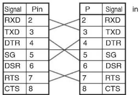
other
| Signal | Pin | P | Signal | |---|---|---|---| | RXD | 2 | 2 | RXD | | TXD | 3 | 3 | TXD | | DTR | 4 | 4 | DTR | | SG | 5 | 5 | SG | | DSR | 6 | 6 | DSR | | RTS | 7 | 7 | RTS | | CTS | 8 | 8 | CTS |
CAUTION
Place the interface cable so that people do not trip on it.
3.3 Ethernet (LAN) Interface
The following describes an overview of the Ethernet (LAN) interface.
For details on this function, refer to a separate manual.
Note that the Ethernet (LAN) interface is not available in the USB + serial model.
Panel button operation
The function of the panel button is as follows.
● Printing network setup information Press the panel button.
- Returning to factory settings Hold down the panel button. A buzzer* will sound and then hold down the panel button again within 3 seconds. It returns network settings to its factory settings. * Depending on settings, the buzzer may not sound.

CAUTION
■ The board will automatically restart after this operation is complete.
■ If settings are configured to obtain an IP address from a DHCP server automatically, the new IP address may be different from the previous one.
LED Functions
The tables below explain how to interpret LED indications.
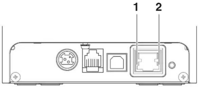
1. Network transmission speed
| Transmission speed LED (green) | |
| 100 Mbps Lit | |
| 10 Mbps/Not connected Unlit | |
2. Network status
| Status LED (yellow) | |
| Connected Lit | |
| Not connected Unlit | |
| Data transmission in progress | Flashing |
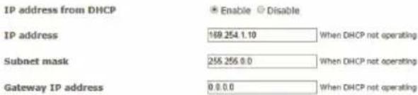
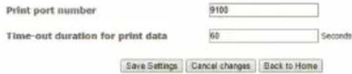
Changing network settings
You can use a web browser to access a special settings page to check and change board settings.
- Access the special settings page
-
Use a web browser to access the URL of the special settings page. Enter the IP address assigned to the printer as the part of URL. (Example: For an IP address of 169.254.1.10, input: http://169.254.1.10.)
-
This displays the page to display the current status.
![Print Server Configuration Host name no name MAC address 00:00:AC:FF:00:D3 Current TCP/IP settings IP address from DHCP On (Enable) IP address 192.168.0.2 Subnet mask 255.255.255.0 Gateway IP address 192.168.0.1 Print settings Print port number 9100 Time-out duration for print data 60 [Second] Change Settings](/content/2026/03/443430/images/9dd08b1db87aa702883b2bb2895e6495929e9b1751125fc38b0faa8763d85766.jpg)
Copyright © 2017 CITIZEN SYSTEMS JAPAN CO.,LTD. All Rights reserved.
- Press the [Change Settings] button to enter the following Change Settings screen. For details, refer to a separate manual.

Print Server Configuration

TCP/IP settings
Print settings
Copyright © 2017 CITIZEN SYSTEMS JAPAN CO.,LTD. All Rights reserved.
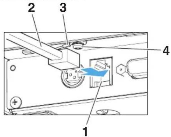
3.4 Connecting the Cash Drawer
- Turn off the power.
- Confirm the orientation of the cash drawer kick-out cable connector and connect it to the cash drawer kick-out connector at the back of the printer.
- Remove the screw for the ground wire.
- Screw the cash drawer's ground wire to the body of the printer.
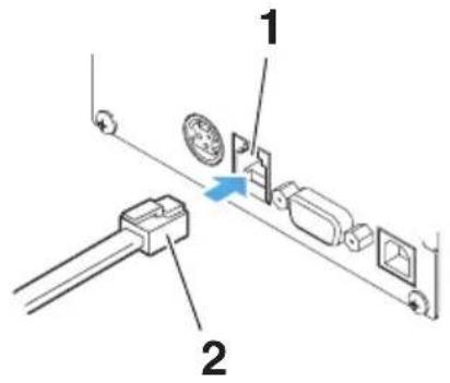
- Cash drawer kick-out connector
- Cash drawer kick-out cable connector
- Ground wire
- Screw for ground wire

CAUTION
■ Connect only the cash drawer kick-out cable to this connector. (Do not connect a telephone line.)
■ Signals cannot be output from the cash drawer kick-out connector while printing.
■ Hold the connector of the drawer kick cable perpendicular and straight when connecting or disconnecting it. Doing it at an angle may cause the connector to misconnect.
(1) Connector pin configuration
| No. | Signal Function | 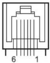 | |
| 1 FG | Frame ground | ||
| 2 DRAWER1 Cash drawer 1 drive signal | |||
| 3 DRSW Cash drawer switch input | |||
| 4 VDR Cash drawer drive power supply | |||
| 5 DRAWER2 Cash drawer 2 drive signal | |||
| 6 GND Signal ground (common ground on circuits) | |||
(2) Electric characteristics
1) Drive voltage: 24 VDC
2) Drive current: Approx. 1 A max. (not to exceed 510 ms.)
3) DRSW signal: Signal levels: "L" = 0 to 0.5 V, "H" = 3 to 5 V
(3) DRSW signal
Status can be tested by commands.
(4) Drive circuit
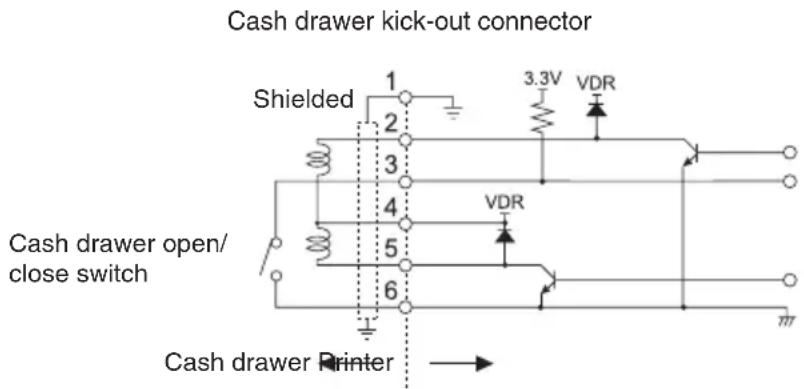

CAUTION
■ Cash drawers 1 and 2 cannot be operated at the same time.
■ The solenoid used for the cash drawer should be 24 Ω or more. Do not allow the electric current to exceed 1 A. Excessive current could damage or burn out the circuits.
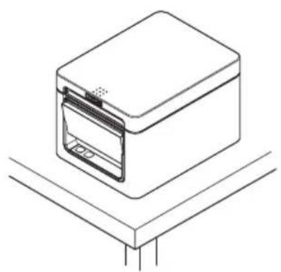
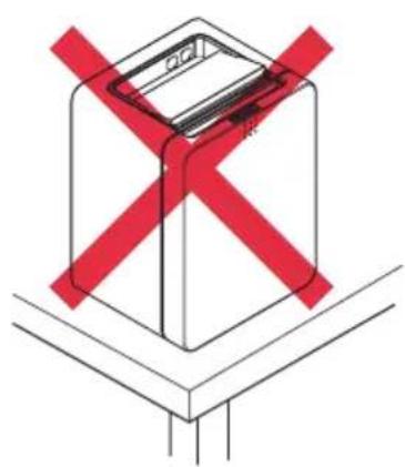
3.5 Precautions for Installing the Printer
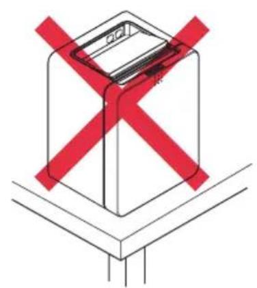
This printer can only be positioned horizontally. It cannot be positioned vertically or on a wall.
natural_image
Line drawing of a rectangular electronic device with a lid and base, placed on a platform (no text or symbols)Horizontal position Vertical position
natural_image
Diagram of a device with red X-shaped warning symbol (no text or labels)
CAUTION
Do not use the printer under the following conditions.
■ Avoid locations subject to vibration or instability.
■ Locations that are very dirty or dusty.
■ Avoid locations where the printer is not level.
• The printer may fall and cause an injury.
• The quality of printing may deteriorate.
■ Oriented other than as specified.
- Malfunction, failure, or electric shock may result.
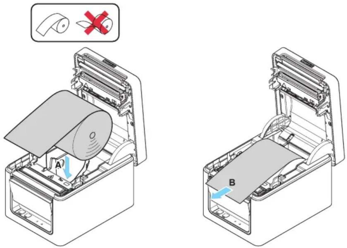
3.6 Loading Paper
- Turn on the power.
- Flip up the cover open lever to open the paper cover.
natural_image
Line drawing of a white rectangular electronic device with a blue internal panel and ventilation slots (no text or symbols)
CAUTION
When pressing up on the lever, take care that you do not pinch your fingers in the gap above the top of the lever.
- Load the paper roll so that the printable side of the paper is facing up, as shown by arrow A.
- Pull a few centimeters of paper straight out in the direction of arrow B.
- Close the paper cover until you hear a click. Paper is fed and cut automatically (by the factory setting).

CAUTION
■ When opening the paper cover, be careful not to touch the entrance of the blade of the auto cutter.
■ The print head is very hot immediately after printing. Be careful not to touch it with your hands.
■ Do not touch the print head with bare hands or metal objects.
■ Always use the specified types of paper rolls.
■ Confirm that the paper roll is set correctly.
■ If the paper is skewed and not coming straight out of the paper cover, open it and straighten the paper.
■ Always pull a few centimeters of paper straight out of the printer if you open the paper cover while paper is loaded.
■ Press on the center of the paper cover to close it securely.
■ Be careful of paper cuts while loading the paper.

Refer to PRECAUTIONS IN HANDLING THE PRINTER
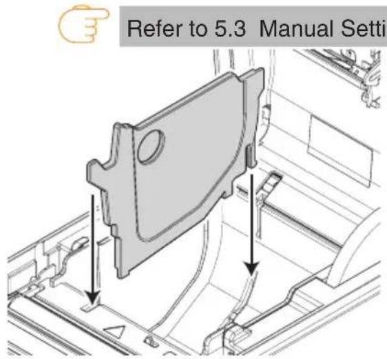
3.7 58-mm Width Roll Paper Partition
- Turn off the power.
- Flip up the cover open lever to open the paper cover.
- Mount the supplied partition to the groove. When using the 80-mm width roll paper, remove the partition.
- Change the print area width while referring to "Manual Settings for the Memory Switches" in Section 5.3.

CAUTION
■ When opening the paper cover, be careful not to touch the entrance of the blade of the auto cutter.
■ The print head is very hot immediately after printing. Be careful not to touch it with your hands.
■ Do not touch the print head with bare hands or metal objects.
■ When using 58-mm wide paper, use the printer as a dedicated printer for that paper size. The printer may not correctly feed paper or print if it is switched to 80-mm wide paper after using 58-mm wide paper.

Refer to PRECAUTIONS IN HANDLING THE PRINTER
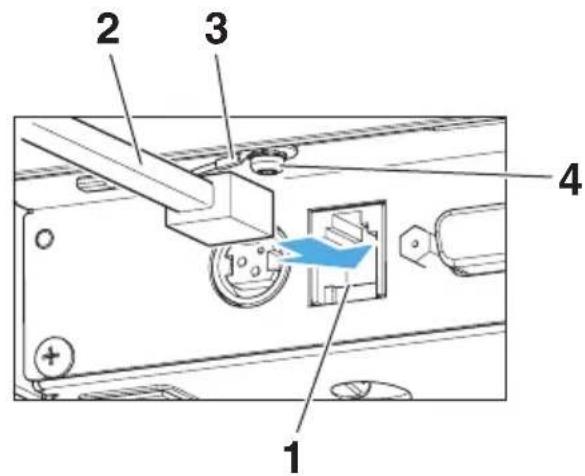
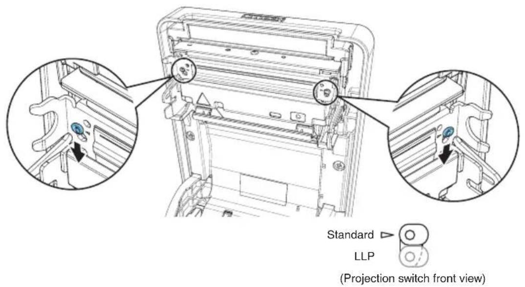
3.8 Setting the Long Life Printing (LLP) Function
It can extend the abrasion life of the head-resistant by reducing the pressure to press the print head against the paper.
The Long Life Printing (LLP) function can be enabled by changing the position of the projection switch inside the paper cover.
- Turn off the power.
- Flip up the cover open lever to open the paper cover.
- Flip down the projection switches on both sides in the arrow direction with the tip of a screwdriver.
Flip down the projection switches on the left and right from the standard position to the LLP position one by one. - Close the paper cover firmly until it clicks.

CAUTION
■ When opening the paper cover, be careful not to touch the entrance of the blade of the auto cutter.
■ The print head is very hot immediately after printing. Be careful not to touch it with your hands.
■ Do not touch the print head with bare hands or metal objects.
■ The set position of the projection switches on the left and right must be identical.
■ When this setting is enabled, the printing density may decrease. If necessary, increase the printing density or use a paper with excellent coloring properties.
■ This function reduces physical friction by reducing the head pressure and does not guarantee friction resistance for all bad quality papers.
3.9 Precautions for Creating Applications and Practical Operations
If printing is done immediately after the paper is partially cut and torn off, the top of the next print out may be distorted.
For printing after cutting, we recommend to print with the first line empty.
If you are using a serial interface that has a slow data transmission speed, streaks may appear in the printouts when you are printing graphics or gradated text, which require large amounts of data.
USB interfaces may be susceptible to the effects of electromagnetic interference from the host or environment.
If this is the case, try using a cable with ferrite cores on both ends, which are very effective at eliminating EMI.
3.10 Download Site for Various Electronic Files
You can view support information and download the latest documents, drivers, utilities, etc. from the following site.
http://www.citizen-systems.co.jp/support/download/printer/ct-e351/
4. MAINTENANCE AND TROUBLESHOOTING
4.1 Periodic Cleaning
A dirty print head or platen may reduce printing quality or cause malfunctions. We recommend cleaning the printer periodically (every 2 to 3 months) as shown below.
- Turn off the power.
- Flip up the cover open lever to open the paper cover.
- Wait a few minutes until the print head cools.
- Use a cotton swab dampened with ethyl alcohol to wipe off any dirt and dust that is on the print head and platen.
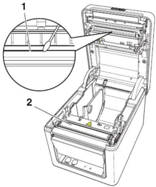
- Print head
- Platen

CAUTION
■ When opening the paper cover, be careful not to touch the entrance of the blade of the auto cutter.
■ The print head is very hot immediately after printing. Be careful not to touch it with your hands.
■ Do not touch the print head with bare hands or metal objects.

Refer to PRECAUTIONS IN HANDLING THE PRINTER
4.2 Clearing a Cutter Error
If the auto cutter stops during the auto cutter operation with the blade of the auto cutter in the open position due to foreign matter entering, paper jamming, etc., the ERROR LED flashes.
When a cutter error occurs, resolve the cutter error with the following procedure.
- Turn off printer power.
- Flip up the cover open lever to open the paper cover.
- Remove any jammed paper including any scraps of paper. (Remove the paper roll that is loaded in the holder also.)
- Reload the paper roll and close the paper cover.
- Turn on the power.

CAUTION
■ When opening the paper cover, be careful not to touch the entrance of the blade of the auto cutter.
■ The print head is very hot immediately after printing. Be careful not to touch it with your hands.
■ Do not touch the print head with bare hands or metal objects.

Refer to PRECAUTIONS IN HANDLING THE PRINTER
4.3 Self Test
You can use self test to check for printer problems.
Performing a self test operation
- While paper is loaded, press and hold the FEED button and turn on the power.
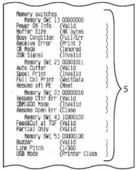
- Hold the FEED button down for about one second until the buzzer sounds. Release the button to start self test. The printer will print its model name, version, memory switch settings, and built-in fonts.
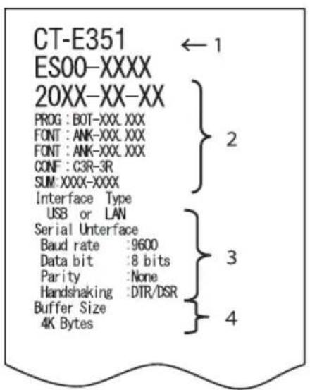
- Printer type name
- Firmware version
- Interface settings
- Buffer size
- Memory switch settings
4.4 Hexadecimal Dump Printing
Print received data in hexadecimal. If problems such as missing or duplicated data occur, this function allows you to check whether or not the printer is receiving data correctly.
How to do hexadecimal dump printing
- Load paper.
- While the paper cover is open, hold down the FEED button as you turn on printing power. Keep FEED button pressing until the POWER LED starts to flash, and then close the paper cover.
- The printer will print "HEX dump print mode" followed by the received data printed in hexadecimal numbers and some characters.
How to stop hexadecimal dump printing
Do one of the following to stop printing.
- Press the FEED button consecutively three times
- Turn off the power
● Receive a reset command from an interface

CAUTION
■ The printer prints “.” if there is no character corresponding to the data.
■ None of the commands function during hexadecimal dump printing.
■ If print data does not cover a complete line, press the FEED button to advance the paper.
Print example
HEX dump print mode
61 62 63 64 65 66 67 0A 0D 0D 0D 0D abcdefg.....
.....DO DO DO
4.5 Error Indications
- Paper End
If the paper ends, the ERROR LED lights and a buzzer sounds. Load a new paper roll. The buzzer may not sound depending on the memory switch setting.
- Cover Open
If the cover is opened, the ERROR LED lights and a buzzer sounds.
The buzzer may not sound depending on the memory switch setting.
Do not open the cover during printing. If the cover is accidentally opened, the ERROR LED flashes. Check the paper, pull it straight out of the printer by a couple of centimeters, and then close the cover. Printing restarts. A command must be sent to restart printing depending on the memory switch setting.
- Cutter Error
If the auto cutter stops due to paper jamming, etc., the ERROR LED flashes. Remove the cause and press the FEED key. If the auto cutter still does not move and the paper cover cannot be opened, refer to “Clearing a Cutter Error.”

Refer to 4.2 Clearing a Cutter Error
- Print Head Hot
Dense printing, heavy black printing, and continuous printing in a high temperature environment increase the temperature of the print head. When the print head exceeds a certain temperature, the printer stops printing and waits until the temperature of the print head decreases. The ERROR LED flashes during this time. When the temperature decreases, printing restarts automatically.
The status display for various messages is shown below.
| Status POWER LED (green) ERROR LED (red) Buzzer sound *3 | |||
| Paper End Lit Lit Yes | |||
| Paper cover or front cover is open *1 | Lit Lit No | ||
| Paper cover or front cover is open *2 | Lit Yes |  | |
| Cutter Error Lit Yes |  | ||
| Memory Error |  | — | No |
| Print Head Hot Lit Yes |  | ||
| Low-voltage Error Lit No |  | ||
| High-voltage Error | Lit No |  | |
| System Error | Lit No |  | |
| Wait for Macro Execution | Lit No |  | |
Notes
*1: This message is displayed when the paper cover or front cover is opened in standby mode.
*2: This message is displayed when the paper cover or front cover is opened during paper feeding or printing.
*3: The buzzer sounds when MSW5-1 (buzzer setting) is enabled. However, the condition that the buzzer sounds varies depending on the MSW5-1 and MSW10-6 settings.
4.6 Paper Jams
Take care to avoid obstruction of the paper outlet and paper jamming around the outlet during printing.
If paper cannot get out of the printer, it can roll up on the platen inside the printer and cause an error.
If the paper wraps around the platen, open the paper cover and carefully pull the paper out.
4.7 Precautions for Performing Printing for Which Printing Speed Changes
When printing for which the printing speed changes is performed, white lines may be printed or paper may not be fed depending on the printing conditions. To prevent these problems, change the following memory switch settings.
- Enable MSW2-3 (buffering).
- Increase the baud rate of MSW7-1 (serial baud rate).
- Change MSW10-2 (print speed) to a lower level.

CAUTION
Depending on the serial interface transmission speed, ambient temperature, print data duty, and other factors, changing the above settings may not eliminate the problems.
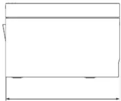
5. OTHER
5.1 External Views and Dimensions
(Unit: mm)
natural_image
Simple line drawing of a rectangular electronic device with a small indicator button at the bottom (no text or symbols)

natural_image
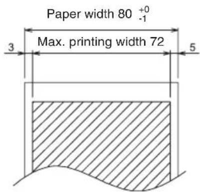
Pure geometric diagram with horizontal and vertical lines, no text or symbols present5.2 Printing Paper
Use the paper shown in the following table or paper of the same quality.
| Paper type Product name | |
| Recommended thermal roll paper | Nippon Paper TP50KR-2Y, TP50KJ-ROji Paper PD150R, PD160R, PD160R-63Mitsubishi Paper Mills HP220AB-1, F230AA, P220ABKoehler KT48-FA |
(Unit: mm)
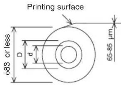
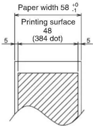
| Paper thickness (μm) 53 to 85 |
| Core inner diameter d (mm) ø12 |
| Core outer diameter D (mm) ø18 |

CAUTION
Use thermal paper that is wound as follows:
■ Not creased and fits tight to the core.
■ Not folded.
■ Not glued to the core.
■ Rolled with the printable side out.
5.3 Manual Setting of Memory Switches
Memory switches are used to set various printer settings. Memory switches can be set manually, or by utilities or commands. This section explains how to perform manual settings.
For information on how to set the memory switches using commands, please refer to the Command Reference.
Individual setting mode
Set the memory switches individually.
Do the settings while confirming the memory switch function and settings on the print-out.
- Load paper.
-
While the paper cover is open, press and hold the FEED button and turn on the power.
-
Press the FEED button twice and close the paper cover.
The printer enters the mode for setting memory switches individually.
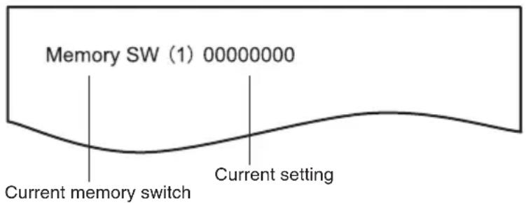
The printer prints "Memory SW (1)" and the current setting, 0 (off) or 1 (on).
(The current settings for memory switches 7 to 13 are not printed.)
- Press the FEED button.
Each press of the FEED button cycles through the list of memory switches in the following sequence: "Memory SW (1)" > "Memory SW (2)" > ..."Memory SW (11)" or "Memory SW (13)" > "Save To Memory" > "Memory SW (1)".
Press the FEED button until the number for the memory switch you want to change is printed.
- Press the FEED button for at least two seconds.
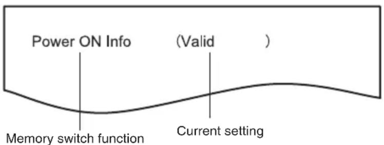
A setting for the memory switch is printed, through the cycle, each time the FEED button is pressed for at least two seconds.
Press the FEED button for at least two seconds to cycle through the list until the function of the memory switch you want to change is printed.
6. Press the FEED button.
A setting is printed each time the FEED button is pressed in order through the cycle.
When the current settings are printed, the COVER LED lights.
Press the FEED button until the setting you want is printed.
7. Press the FEED button for at least two seconds.
The selected settings are set.
The next memory switch function and settings are printed.
8. Repeat steps 5 to 7 to change different functions for the current memory switch number.
9. Open the paper cover and close it.
The changed memory switch settings are printed.
10. Repeat steps 4 to 9 to change functions for a different memory switch number.
11. Press the FEED button until "Save To Memory" is printed.
12. Press the FEED button for at least two seconds.
The changed memory switch settings are saved and a list of them is printed.
The printer exits individual setting mode when printing is finished.
Memory switch initialization
Set all the memory switches to the factory settings.
-
Do steps 1 through 3 of the procedure to enter individual setting mode.
-
Press the FEED button until "Save To Memory" is printed.
-
Open the paper cover.
-
Press the FEED button for at least two seconds.
All memory switches change to the factory settings.
- Close the paper cover.
The function of each memory switch is shown in the following table. (Shaded values are factory settings.)
| Switch no. Function OFF ON | |||
| MSW1-1 Power ON Info Valid Not Send | |||
| MSW1-2 Buffer Size 4K bytes 45 bytes | |||
| MSW1-3 Busy Condition Full/Err Full | |||
| MSW1-4 Receive Error Print“?” No Print | |||
| MSW1-5 | CR Mode Ignored | LF | |
| MSW1-6 | Reserved | Fixed — | |
| MSW1-7 | DSR Signal | Invalid | Valid |
| MSW1-8 | Reserved | Fixed — | |
| MSW2-1 | Reserved | — | Fixed |
| MSW2-2 | Auto Cutter | Invalid | Valid |
| MSW2-3 Spool Print Invalid | Valid | ||
| MSW2-4 | Full Col Print | LineFeed | WaitData |
| MSW2-5 Resume aft PE Next | Top | ||
| MSW2-6 | Reserved | Fixed — | |
| MSW2-7 | Reserved | Fixed — | |
| MSW2-8 | Reserved | Fixed — | |
| MSW3-1 | Resume Ctr Err | Valid | Invalid |
| MSW3-2 | Reserved | Fixed — | |
| MSW3-3 | Reserved | Fixed — | |
| MSW3-4 | Reserved | Fixed — | |
| MSW3-5 | Reserved | Fixed — | |
| MSW3-6 | Reserved | Fixed — | |
| MSW3-7 | CBM1000 Mode | Invalid | Valid |
| MSW3-8 | Resume Open Err Close | Command | |
| MSW4-1 | Reserved | Fixed — | |
| MSW4-2 | Reserved | Fixed — | |
| MSW4-3 | Feed&Cut at TOF Invalid | Valid | |
| MSW4-4 | Reserved | Fixed — | |
| MSW4-5 | Reserved | Fixed — | |
| MSW4-6 | Reserved | Fixed — | |
| MSW4-7 | Reserved | Fixed — | |
| MSW4-8 | Partial Only | Invalid | Valid |
| MSW5-1 Buzzer Valid Invalid | |||
| MSW5-2 Line Pitch 1/360 1/406 | |||
| MSW5-3 USB Mode Virtual COM Printer Class | |||
| MSW5-4 Reserved Fixed — | |||
| MSW5-5 Reserved Fixed — | |||
| MSW5-6 Reserved Fixed — | |||
| MSW5-7 Reserved Fixed — | |||
| MSW5-8 Reserved Fixed — | |||
| MSW6-1 | Act. For Driver Invalid Valid | ||
| MSW6-2 | Character Space Invalid Valid | ||
| MSW6-3 | USB Power Save | Invalid Valid | |
| MSW6-4 Reserved Fixed — | |||
| MSW6-5 Reserved Fixed — | |||
| MSW6-6 Reserved Fixed — | |||
| MSW6-7 Reserved Fixed — | |||
| MSW6-8 | Power ON trigger | Power switch ON | AC power input |
| Switch no. | Function | Initial setting | Setting value |
| MSW7-1 | Baud Rate | 9600 bps | 1200 bps, 2400 bps, 4800 bps, 9600 bps, 19200 bps, 38400 bps, 57600 bps, 115200 bps |
| MSW7-2 | Data Length | 8bits | 7bits, 8bits |
| MSW7-3 | Stop Bit | 1bit | 1bit, 2bits |
| MSW7-4 | Parity | NONE | NONE, ODD, EVEN |
| MSW7-5 | Flow Control | DTR/DSR | DTR/DSR, XON/XOFF |
| MSW7-6 | DMA Control | Valid | Valid, Invalid |
| MSW7-7 | VCom Protocol | PC Setting | PC Setting, DTR/DSR, XON/XOFF |
| MSW8-1 | Print Width | 576 dots | 576 dots, 546 dots, 512 dots, 420 dots, 390 dots, 384 dots, 360 dots |
| MSW8-3 | Top Margin | 11mm | 3mm, 4mm, 5mm, 6mm, 7mm, 8mm, 9mm, 10mm, 11mm |
| MSW8-4 | Line Gap Reduce | Invalid | Invalid, 3/4, 2/3, 1/2, 1/3, 1/4, 1/5, ALL |
| MSW8-5 | Reduced Char V/H | 100% / 100% | 100% / 100%, 75% / 100%, 50% / 100%, 100% / 75%, 75% / 75%, 50% / 75% |
| MSW8-6 | Auto Side Shift | Invalid | Invalid, 1 dot, 2 dots, 3 dots, 4 dots, 5 dots, 6 dots, 7 dots |
| MSW8-7 | Liner Free Mode | Invalid | Disabled, 1 h, 6 h, 12 h, 18 h, 24 h, 5 m, 10 m 15 m, 20 m, 30 m |
| Switch no. | Function Initial setting | Setting value | |
| MSW9-1 Code | Page PC437 PC 437 | , Katakana, PC | 850, PC 858, PC 860, PC 863,PC 865, PC 852, PC 866, PC 857, WPC1252, Spacepage, PC 864, ThaiCode11 1Pass, ThaiCode113Pass, ThaiCode18 1Pass, ThaiCode18 3Pass,TCVN-3 |
| MSW9-2 Int' | Char Set USA USA, France, Germany, | England, Denmark, Sweden,Italy, Spain, Japan, Norway, Denmark 2, Spain 2, LatinAmerica, Korea, Croatia, China, Vietnam | |
| MSW9-4 Kanji code | Invalid Disabled, JIS (Japan), S | JIS: CP932 (Japan), SJIS:X0213 (Japan), GB18030 (China), KS Hangul (SouthKorea), EUC Hangul (South Korea), BIG5 (Taiwan) | |
| MSW10-1 | Print Density | 100 % | 70 %, 75 %, 80 %, 85 %, 90 %, 95 %, 100 %, 105 %,110 %, 115 %, 120 %, 125 %, 130 %, 135 %, 140 % |
| MSW10-2 | Print Speed | Level 9 | Level 1, Level 2, Level 3, Level 4, Level 5, Level 6,Level 7, Level 8, Level 9 |
| MSW10-4 | Old Command Invalid Invalid, CBM | 1, CBM2 | |
| MSW10-5 Buzzer Event Not | By C.Open | All Event/Error, Not by C.Open, Not by C.Open/PE | |
| MSW10-6 | Buzzer Sound Tone 2 Tone 1, Tone 2, Tone 3, Tone 4 | ||
FRANÇAIS
PRÉCAUTIONS GÉNÉRALES
natural_image
Technical line drawing showing two installation or connection setups with labeled components (no text or symbols present)Copyright © 2017 CITIZEN SYSTEMS JAPAN CO.,LTD. All Rights reserved.
Print settings

Copyright © 2017 CITIZEN SYSTEMS JAPAN CO.,LTD. All Rights reserved.
natural_image
Line drawing of a rectangular electronic device with a label and mounting base (no text or symbols)Position horizontale Position verticale
natural_image
Diagram of a device with red X-shaped warning sign and no visible text or symbols
ATTENTION
natural_image
Line drawing of a white rectangular electronic device with a blue internal panel and ventilation slots (no text or symbols)
ATTENTION
natural_image
Technical diagram of a mechanical component with arrows indicating assembly or movement (no text or symbols present)
ATTENTION
natural_image
Simple line drawing of a rectangular electronic device with a small indicator button at the bottom (no text or symbols)

natural_image
Pure geometric diagram with horizontal and vertical lines, no text or symbols present| N° de commutateur Fonction OFF ON | |||
| MSW1-1 Power ON Info Valid Not Send | |||
| MSW1-2 Buffer Size 4K bytes 45 bytes | |||
| MSW1-3 Busy Condition Full/Err Full | |||
| MSW1-4 Receive Error Print“?” No Print | |||
| MSW1-5 | CR Mode Ignored | LF | |
| MSW1-6 | Reserved | Fixed — | |
| MSW1-7 | DSR Signal | Invalid | Valid |
| MSW1-8 | Reserved | Fixed — | |
| MSW2-1 | Reserved | — | Fixed |
| MSW2-2 | Auto Cutter | Invalid | Valid |
| MSW2-3 Spool Print Invalid | Valid | ||
| MSW2-4 | Full Col Print | LineFeed | WaitData |
| MSW2-5 Resume aft PE Next | Top | ||
| MSW2-6 | Reserved | Fixed — | |
| MSW2-7 | Reserved | Fixed — | |
| MSW2-8 | Reserved | Fixed — | |
| MSW3-1 | Resume Ctr Err Valid | Invalid | |
| MSW3-2 | Reserved | Fixed — | |
| MSW3-3 | Reserved | Fixed — | |
| MSW3-4 | Reserved | Fixed — | |
| MSW3-5 | Reserved | Fixed — | |
| MSW3-6 | Reserved | Fixed — | |
| MSW3-7 | CBM1000 Mode | Invalid | Valid |
| MSW3-8 | Resume Open Err Close | Command | |
| MSW4-1 | Reserved | Fixed — | |
| MSW4-2 | Reserved | Fixed — | |
| MSW4-3 | Feed&Cut at TOF Invalid | Valid | |
| MSW4-4 | Reserved | Fixed — | |
| MSW4-5 | Reserved | Fixed — | |
| MSW4-6 | Reserved | Fixed — | |
| MSW4-7 | Reserved | Fixed — | |
| MSW4-8 | Partial Only | Invalid | Valid |
| MSW5-1 Buzzer Valid Invalid | |||
| MSW5-2 Line Pitch 1/360 1/406 | |||
| MSW5-3 USB Mode Virtual COM Printer Class | |||
| MSW5-4 Reserved Fixed — | |||
| MSW5-5 Reserved Fixed — | |||
| MSW5-6 Reserved Fixed — | |||
| MSW5-7 Reserved Fixed — | |||
| MSW5-8 Reserved Fixed — | |||
| MSW6-1 | Act. For Driver | Invalid Valid | |
| MSW6-2 | Character Space Invalid Valid | ||
| MSW6-3 | USB Power Save | Invalid Valid | |
| MSW6-4 Reserved Fixed — | |||
| MSW6-5 Reserved Fixed — | |||
| MSW6-6 Reserved Fixed — | |||
| MSW6-7 Reserved Fixed — | |||
| MSW6-8 | Power ON trigger | Power switch ON | AC power input |
| N° de commu-tateur | Fonction | Initial setting | Setting value |
| MSW7-1 | Baud Rate | 9600 bps | 1200 bps, 2400 bps, 4800 bps, 9600 bps, 19200 bps, 38400 bps, 57600 bps, 115200 bps |
| MSW7-2 | Data Length | 8bits | 7bits, 8bits |
| MSW7-3 | Stop Bit | 1bit | 1bit, 2bits |
| MSW7-4 | Parity | NONE | NONE, ODD, EVEN |
| MSW7-5 | Flow Control | DTR/DSR | DTR/DSR, XON/XOFF |
| MSW7-6 | DMA Control | Valid | Valid, Invalid |
| MSW7-7 | VCom Protocol | PC Setting | PC Setting, DTR/DSR, XON/XOFF |
| MSW8-1 | Print Width | 576 dots | 576 dots, 546 dots, 512 dots, 420 dots, 390 dots, 384 dots, 360 dots |
| MSW8-3 | Top Margin | 11mm | 3mm, 4mm, 5mm, 6mm, 7mm, 8mm, 9mm, 10mm, 11mm |
| MSW8-4 | Line Gap Reduce | Invalid | Invalid, 3/4, 2/3, 1/2, 1/3, 1/4, 1/5, ALL |
| MSW8-5 | Reduced Char V/H | 100% / 100% | 100% / 100%, 75% / 100%, 50% / 100%, 100% / 75%, 75% / 75%, 50% / 75% |
| MSW8-6 | Auto Side Shift | Invalid | Invalid, 1 dot, 2 dots, 3 dots, 4 dots, 5 dots, 6 dots, 7 dots |
| MSW8-7 | Liner Free Mode | Invalid | Disabled, 1 h, 6 h, 12 h, 18 h, 24 h, 5 m, 10 m 15 m, 20 m, 30 m |
| N° de commu-tateur | Fonction Initial setting Setting value | ||
| MSW9-1 Code | Page PC437 PC 437, Katakana, PC | 850, PC 858, PC 860, PC 863,PC 865, PC 852, PC 866, PC 857, WPC1252, Spacepage, PC 864, ThaiCode11 1Pass, ThaiCode113Pass, ThaiCode18 1Pass, ThaiCode18 3Pass,TCVN-3 | |
| MSW9-2 Int' | Char Set USA USA, France, Germany, | England, Denmark, Sweden,Italy, Spain, Japan, Norway, Denmark 2, Spain 2, LatinAmerica, Korea, Croatia, China, Vietnam | |
| MSW9-4 | Kanji code Invalid | Disabled, JIS (Japan), SJIS: CP932 (Japan), SJIS:X0213 (Japan), GB18030 (China), KS Hangul (SouthKorea), EUC Hangul (South Korea), BIG5 (Taiwan) | |
| MSW10-1 Print Density 100 % 70 %, 75 %, 80 %, 85 %, 90 %, 95 %, 100 %, 105 %,110 %, 115 %, 120 %, 125 %, 130 %, 135 %, 140 % | |||
| MSW10-2 | Print Speed | Level 9 | Level 1, Level 2, Level 3, Level 4, Level 5, Level 6,Level 7, Level 8, Level 9 |
| MSW10-4 | Old Command | Invalid Invalid, CBM1, CBM2 | |
| MSW10-5 | Buzzer Event Not By C.Open | All Event/Error, Not by C.Open, Not by C.Open/PE | |
| MSW10-6 | Buzzer Sound | Tone 2 Tone 1, Tone 2, Tone 3, Tone 4 | |
DEUTSCH
natural_image
Technical line drawing showing two installation or connection setups with connectors and components (no text or symbols)USB + seriell Ethernet + USB

VORSICHT
Copyright © 2017 CITIZEN SYSTEMS JAPAN CO.,LTD. All Rights reserved.
Print settings
Copyright © 2017 CITIZEN SYSTEMS JAPAN CO.,LTD. All Rights reserved.

natural_image
Line drawing of a rectangular electronic device with a lid and base, placed on a surface (no text or symbols)natural_image
Diagram of a mechanical component with red X-shaped constraints and no visible text or symbols
VORSICHT
natural_image
Line drawing of a rectangular electronic device with a blue internal panel and labeled ports (no text or symbols)
VORSICHT
natural_image
Technical diagram of a mechanical component with arrows indicating assembly or movement (no text or symbols present)
VORSICHT
natural_image
Simple line drawing of a rectangular electronic device with a small indicator button at the bottom (no text or symbols)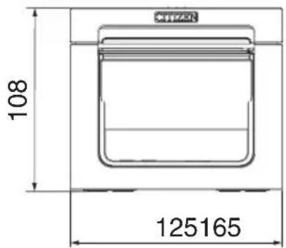

natural_image
Pure geometric diagram with horizontal and vertical lines, no text or symbols present5.2 Druckpapier
| Schalter-Nr. Funktion OFF ON | |||
| MSW1-1 Power ON Info Valid Not Send | |||
| MSW1-2 Buffer Size 4K bytes 45 bytes | |||
| MSW1-3 Busy Condition Full/Err Full | |||
| MSW1-4 Receive Error Print“?” | No Print | ||
| MSW1-5 | CR Mode Ignored | LF | |
| MSW1-6 | Reserved | Fixed — | |
| MSW1-7 | DSR Signal | Invalid | Valid |
| MSW1-8 | Reserved | Fixed — | |
| MSW2-1 | Reserved | — | Fixed |
| MSW2-2 | Auto Cutter | Invalid | Valid |
| MSW2-3 Spool Print Invalid | Valid | ||
| MSW2-4 | Full Col Print LineFeed | WaitData | |
| MSW2-5 Resume aft PE Next | Top | ||
| MSW2-6 | Reserved | Fixed — | |
| MSW2-7 | Reserved | Fixed — | |
| MSW2-8 | Reserved | Fixed — | |
| MSW3-1 | Resume Ctr Err Valid | Invalid | |
| MSW3-2 | Reserved | Fixed — | |
| MSW3-3 | Reserved | Fixed — | |
| MSW3-4 | Reserved | Fixed — | |
| MSW3-5 | Reserved | Fixed — | |
| MSW3-6 | Reserved | Fixed — | |
| MSW3-7 | CBM1000 Mode | Invalid | Valid |
| MSW3-8 | Resume Open Err Close | Command | |
| MSW4-1 | Reserved | Fixed — | |
| MSW4-2 | Reserved | Fixed — | |
| MSW4-3 | Feed&Cut at TOF Invalid | Valid | |
| MSW4-4 | Reserved | Fixed — | |
| MSW4-5 | Reserved | Fixed — | |
| MSW4-6 | Reserved | Fixed — | |
| MSW4-7 | Reserved | Fixed — | |
| MSW4-8 | Partial Only | Invalid | Valid |
| MSW5-1 Buzzer Valid Invalid | |||
| MSW5-2 Line Pitch 1/360 1/406 | |||
| MSW5-3 USB Mode Virtual COM Printer Class | |||
| MSW5-4 Reserved | Fixed — | ||
| MSW5-5 Reserved | Fixed — | ||
| MSW5-6 Reserved | Fixed — | ||
| MSW5-7 Reserved | Fixed — | ||
| MSW5-8 Reserved | Fixed — | ||
| MSW6-1 | Act. For Driver | Invalid Valid | |
| MSW6-2 | Character Space Invalid | Valid | |
| MSW6-3 | USB Power Save | Invalid | Valid |
| MSW6-4 Reserved | Fixed — | ||
| MSW6-5 Reserved | Fixed — | ||
| MSW6-6 Reserved | Fixed — | ||
| MSW6-7 Reserved | Fixed — | ||
| MSW6-8 | Power ON trigger | Power switch ON | AC power input |
| Schalter-Nr. | Funktion | Voreinstel-lung | Einstellwert |
| MSW7-1 | Baud Rate | 9600 bps | 1200 bps, 2400 bps, 4800 bps, 9600 bps, 19200 bps, 38400 bps, 57600 bps, 115200 bps |
| MSW7-2 | Data Length | 8bits | 7bits, 8bits |
| MSW7-3 | Stop Bit | 1bit | 1bit, 2bits |
| MSW7-4 | Parity | NONE | NONE, ODD, EVEN |
| MSW7-5 | Flow Control | DTR/DSR | DTR/DSR, XON/XOFF |
| MSW7-6 | DMA Control | Valid | Valid, Invalid |
| MSW7-7 | VCom Protocol | PC Setting | PC Setting, DTR/DSR, XON/XOFF |
| MSW8-1 | Print Width | 576 dots | 576 dots, 546 dots, 512 dots, 420 dots, 390 dots, 384 dots, 360 dots |
| MSW8-3 | Top Margin | 11mm | 3mm, 4mm, 5mm, 6mm, 7mm, 8mm, 9mm, 10mm, 11mm |
| MSW8-4 | Line Gap Reduce | Invalid | Invalid, 3/4, 2/3, 1/2, 1/3, 1/4, 1/5, ALL |
| MSW8-5 | Reduced Char V/H | 100% / 100% | 100% / 100%, 75% / 100%, 50% / 100%, 100% / 75%, 75% / 75%, 50% / 75% |
| MSW8-6 | Auto Side Shift | Invalid | Invalid, 1 dot, 2 dots, 3 dots, 4 dots, 5 dots, 6 dots, 7 dots |
| MSW8-7 | Liner Free Mode | Invalid | Disabled, 1 h, 6 h, 12 h, 18 h, 24 h, 5 m, 10 m 15 m, 20 m, 30 m |
| Schalter-Nr. | Funktion Voreinstel- | lung | Einstellwert |
| MSW9-1 | Code Page PC437 PC 437, Katakana, PC | 850, PC 858, PC 860, PC 863,PC 865, PC 852, PC 866, PC 857, WPC1252, Spacepage, PC 864, ThaiCode11 1Pass, ThaiCode113Pass, ThaiCode18 1Pass, ThaiCode18 3Pass,TCVN-3 | |
| MSW9-2 | Int'Char Set USA USA, France, Germany, | England, Denmark, Sweden,Italy, Spain, Japan, Norway, Denmark 2, Spain 2, LatinAmerica, Korea, Croatia, China, Vietnam | |
| MSW9-4 | Kanji code Invalid | Disabled, JIS (Japan), SJIS: CP932 (Japan), SJIS:X0213 (Japan), GB18030 (China), KS Hangul (SouthKorea), EUC Hangul (South Korea), BIG5 (Taiwan) | |
| MSW10-1 | Print Density 100 % 70 %, 75 %, 80 %, 85 | %, 90 %, 95 %, 100 %, 105 %,110 %, 115 %, 120 %, 125 %, 130 %, 135 %, 140 % | |
| MSW10-2 | Print Speed | Level 9 | Level 1, Level 2, Level 3, Level 4, Level 5, Level 6,Level 7, Level 8, Level 9 |
| MSW10-4 | Old Command Invalid Invalid, CBM1, CBM2 | ||
| MSW10-5 | Buzzer Event Not By C.Open | All Event/Error, Not by C.Open, Not by C.Open/PE | |
| MSW10-6 | Buzzer Sound Tone 2 Tone 1, Tone 2, Tone 3, Tone 4 | ||
ITALIANO
natural_image
Technical line drawing showing two installation or assembly steps of connected electronic components (no text or symbols present)USB + seriale Ethernet + USB

ATTENZIONE
Copyright © 2017 CITIZEN SYSTEMS JAPAN CO.,LTD. All Rights reserved.
Print settings

Copyright © 2017 CITIZEN SYSTEMS JAPAN CO.,LTD. All Rights reserved.

natural_image
Line drawing of a rectangular electronic device with a lid and base, placed on a surface (no text or symbols)natural_image
Diagram of a mechanical component with red X-shaped constraints and no visible text or symbols
ATTENZIONE
natural_image
Line drawing of a rectangular electronic device with a blue internal panel and labeled ports (no text or symbols)
ATTENZIONE
natural_image
Technical diagram of a mechanical component with arrows indicating assembly or movement (no text or symbols present)
ATTENZIONE
natural_image
Simple line drawing of a rectangular electronic device with a small indicator button at the bottom (no text or symbols)
natural_image
Pure geometric diagram with horizontal and vertical lines, no text or symbols present| N. switch Funzione OFF ON | |||
| MSW1-1 Power ON Info Valid Not Send | |||
| MSW1-2 Buffer Size 4K bytes 45 bytes | |||
| MSW1-3 Busy Condition Full/Err Full | |||
| MSW1-4 Receive Error Print“?” No Print | |||
| MSW1-5 Mode Ignored LF | |||
| MSW1-6 | Reserved | Fixed — | |
| MSW1-7 | DSR Signal | Invalid | Valid |
| MSW1-8 | Reserved | Fixed — | |
| MSW2-1 | Reserved | — | Fixed |
| MSW2-2 | Auto Cutter | Invalid | Valid |
| MSW2-3 Spool Print Invalid | Valid | ||
| MSW2-4 | Full Col Print | LineFeed | WaitData |
| MSW2-5 Resume aft PE Next | Top | ||
| MSW2-6 | Reserved | Fixed — | |
| MSW2-7 | Reserved | Fixed — | |
| MSW2-8 | Reserved | Fixed — | |
| MSW3-1 | Resume Ctr Err Valid | Invalid | |
| MSW3-2 | Reserved | Fixed — | |
| MSW3-3 | Reserved | Fixed — | |
| MSW3-4 | Reserved | Fixed — | |
| MSW3-5 | Reserved | Fixed — | |
| MSW3-6 | Reserved | Fixed — | |
| MSW3-7 | CBM1000 Mode | Invalid | Valid |
| MSW3-8 | Resume Open Err Close | Command | |
| MSW4-1 | Reserved | Fixed — | |
| MSW4-2 | Reserved | Fixed — | |
| MSW4-3 | Feed&Cut at TOF | Invalid | Valid |
| MSW4-4 | Reserved | Fixed — | |
| MSW4-5 | Reserved | Fixed — | |
| MSW4-6 | Reserved | Fixed — | |
| MSW4-7 | Reserved | Fixed — | |
| MSW4-8 | Partial Only | Invalid | Valid |
| MSW5-1 Buzzer Valid Invalid | |||
| MSW5-2 Line Pitch 1/360 1/406 | |||
| MSW5-3 USB Mode Virtual COM Printer Class | |||
| MSW5-4 Reserved Fixed — | |||
| MSW5-5 Reserved Fixed — | |||
| MSW5-6 Reserved Fixed — | |||
| MSW5-7 Reserved Fixed — | |||
| MSW5-8 Reserved Fixed — | |||
| MSW6-1 Act. For Driver Invalid Valid | |||
| MSW6-2 | Character Space | Invalid Valid | |
| MSW6-3 | USB Power Save | Invalid Valid | |
| MSW6-4 Reserved Fixed — | |||
| MSW6-5 Reserved Fixed — | |||
| MSW6-6 Reserved Fixed — | |||
| MSW6-7 Reserved Fixed — | |||
| MSW6-8 | Power ON trigger | Power switch ON | AC power input |
| N. switch | Funzione | Initial setting | Setting value |
| MSW7-1 | Baud Rate | 9600 bps | 1200 bps, 2400 bps, 4800 bps, 9600 bps, 19200 bps, 38400 bps, 57600 bps, 115200 bps |
| MSW7-2 | Data Length | 8bits | 7bits, 8bits |
| MSW7-3 | Stop Bit | 1bit | 1bit, 2bits |
| MSW7-4 | Parity | NONE | NONE, ODD, EVEN |
| MSW7-5 | Flow Control | DTR/DSR | DTR/DSR, XON/XOFF |
| MSW7-6 | DMA Control | Valid | Valid, Invalid |
| MSW7-7 | VCom Protocol | PC Setting | PC Setting, DTR/DSR, XON/XOFF |
| MSW8-1 | Print Width | 576 dots | 576 dots, 546 dots, 512 dots, 420 dots, 390 dots, 384 dots, 360 dots |
| MSW8-3 | Top Margin | 11mm | 3mm, 4mm, 5mm, 6mm, 7mm, 8mm, 9mm, 10mm, 11mm |
| MSW8-4 | Line Gap Reduce | Invalid | Invalid, 3/4, 2/3, 1/2, 1/3, 1/4, 1/5, ALL |
| MSW8-5 | Reduced Char V/H | 100% / 100% | 100% / 100%, 75% / 100%, 50% / 100%, 100% / 75%, 75% / 75%, 50% / 75% |
| MSW8-6 | Auto Side Shift | Invalid | Invalid, 1 dot, 2 dots, 3 dots, 4 dots, 5 dots, 6 dots, 7 dots |
| MSW8-7 | Liner Free Mode | Invalid | Disabled, 1 h, 6 h, 12 h, 18 h, 24 h, 5 m, 10 m 15 m, 20 m, 30 m |
| N. switch Funzione Initial setting | Setting value | ||
| MSW9-1 Code | Page PC437 PC 437 | , Katakana, PC | 850, PC 858, PC 860, PC863, PC 865, PC 852, PC 866, PC 857, WPC1252,Space page, PC 864, ThaiCode11 1Pass, ThaiCode11 3Pass, ThaiCode18 1Pass, ThaiCode18 3Pass,TCVN-3 |
| MSW9-2 Int' | Char Set USA USA, France, Germany, | England, Denmark, Sweden,Italy, Spain, Japan, Norway, Denmark 2, Spain 2, LatinAmerica, Korea, Croatia, China, Vietnam | |
| MSW9-4 Kanji code | Invalid Disabled, JIS (Japan), S | JIS: CP932 (Japan), SJIS:X0213 (Japan), GB18030 (China), KS Hangul (SouthKorea), EUC Hangul (South Korea), BIG5 (Taiwan) | |
| MSW10-1 | Print Density | 100 % | 70 %, 75 %, 80 %, 85 %, 90 %, 95 %, 100 %, 105 %,110 %, 115 %, 120 %, 125 %, 130 %, 135 %, 140 % |
| MSW10-2 | Print Speed | Level 9 | Level 1, Level 2, Level 3, Level 4, Level 5, Level 6,Level 7, Level 8, Level 9 |
| MSW10-4 | Old Command | Invalid | Invalid, CBM1, CBM2 |
| MSW10-5 | Buzzer Event | Not By C.Open | All Event/Error, Not by C.Open, Not by C.Open/PE |
| MSW10-6 | Buzzer Sound | Tone 2 Tone 1, Tone 2, Tone 3, Tone 4 | |
ESPAÑOL
PRECAUCIONES GENERALES
natural_image
Diagram showing two electrical connector assemblies with connectors and wiring (no text or labels)Copyright © 2017 CITIZEN SYSTEMS JAPAN CO.,LTD. All Rights reserved.
Print settings

Copyright © 2017 CITIZEN SYSTEMS JAPAN CO.,LTD. All Rights reserved.

natural_image
Isometric line drawing of a rectangular electronic device with a label on its side (no text or symbols present)natural_image
Diagram of a device with red X-shaped warning sign and no visible text or symbols
PRECAUCIÓN
natural_image
Line drawing of a rectangular electronic device with a blue internal panel and ventilation slots (no text or symbols)
PRECAUCIÓN
natural_image
Technical diagram of a mechanical component with arrows indicating assembly or movement (no text or symbols present)
PRECAUCIÓN
natural_image
Simple line drawing of a rectangular electronic device with a small indicator button at the bottom (no text or symbols)

natural_image
Pure geometric diagram with horizontal and vertical lines, no text or symbols present| N.° de interruptor Función OFF ON | |||
| MSW1-1 Power ON Info Valid Not Send | |||
| MSW1-2 Buffer Size 4K bytes 45 bytes | |||
| MSW1-3 Busy Condition Full/Err Full | |||
| MSW1-4 Receive Error Print“?” No Print | |||
| MSW1-5 CR Mode Ignored | LF | ||
| MSW1-6 Reserved | Fixed — | ||
| MSW1-7 | DSR Signal | Invalid | Valid |
| MSW1-8 Reserved | Fixed — | ||
| MSW2-1 Reserved | — | Fixed | |
| MSW2-2 | Auto Cutter | Invalid | Valid |
| MSW2-3 Spool Print | Invalid | Valid | |
| MSW2-4 | Full Col Print | LineFeed | WaitData |
| MSW2-5 Resume aft PE Next | Top | ||
| MSW2-6 Reserved | Fixed — | ||
| MSW2-7 Reserved | Fixed — | ||
| MSW2-8 Reserved | Fixed — | ||
| MSW3-1 | Resume Ctr Err Valid | Invalid | |
| MSW3-2 Reserved | Fixed — | ||
| MSW3-3 Reserved | Fixed — | ||
| MSW3-4 Reserved | Fixed — | ||
| MSW3-5 Reserved | Fixed — | ||
| MSW3-6 Reserved | Fixed — | ||
| MSW3-7 | CBM1000 Mode | Invalid | Valid |
| MSW3-8 | Resume Open Err Close | Command | |
| MSW4-1 Reserved | Fixed — | ||
| MSW4-2 Reserved | Fixed — | ||
| MSW4-3 | Feed&Cut at TOF | Invalid | Valid |
| MSW4-4 Reserved | Fixed — | ||
| MSW4-5 Reserved | Fixed — | ||
| MSW4-6 Reserved | Fixed — | ||
| MSW4-7 Reserved | Fixed — | ||
| MSW4-8 | Partial Only | Invalid | Valid |
| MSW5-1 Buzzer Valid Invalid | |||
| MSW5-2 Line Pitch 1/360 1/406 | |||
| MSW5-3 USB Mode Virtual COM Printer Class | |||
| MSW5-4 Reserved Fixed — | |||
| MSW5-5 Reserved Fixed — | |||
| MSW5-6 Reserved Fixed — | |||
| MSW5-7 Reserved Fixed — | |||
| MSW5-8 Reserved Fixed — | |||
| MSW6-1 | Act. For Driver | Invalid Valid | |
| MSW6-2 | Character Space Invalid Valid | ||
| MSW6-3 | USB Power Save Mode | Invalid Valid | |
| MSW6-4 Reserved Fixed — | |||
| MSW6-5 Reserved Fixed — | |||
| MSW6-6 Reserved Fixed — | |||
| MSW6-7 Reserved Fixed — | |||
| MSW6-8 | Power ON trigger | Power switch ON | AC power input |
| N.° de inter-ruptor | Función | Initial setting | Setting value |
| MSW7-1 | Baud Rate | 9600 bps | 1200 bps, 2400 bps, 4800 bps, 9600 bps, 19200 bps, 38400 bps, 57600 bps, 115200 bps |
| MSW7-2 | Data Length | 8bits | 7bits, 8bits |
| MSW7-3 | Stop Bit | 1bit | 1bit, 2bits |
| MSW7-4 | Parity | NONE | NONE, ODD, EVEN |
| MSW7-5 | Flow Control | DTR/DSR | DTR/DSR, XON/XOFF |
| MSW7-6 | DMA Control | Valid | Valid, Invalid |
| MSW7-7 | VCom Protocol | PC Setting | PC Setting, DTR/DSR, XON/XOFF |
| MSW8-1 | Print Width | 576 dots | 576 dots, 546 dots, 512 dots, 420 dots, 390 dots, 384 dots, 360 dots |
| MSW8-3 | Top Margin | 11mm | 3mm, 4mm, 5mm, 6mm, 7mm, 8mm, 9mm, 10mm, 11mm |
| MSW8-4 | Line Gap Reduce | Invalid | Invalid, 3/4, 2/3, 1/2, 1/3, 1/4, 1/5, ALL |
| MSW8-5 | Reduced Char V/H | 100% / 100% | 100% / 100%, 75% / 100%, 50% / 100%, 100% / 75%, 75% / 75%, 50% / 75% |
| MSW8-6 | Auto Side Shift | Invalid | Invalid, 1 dot, 2 dots, 3 dots, 4 dots, 5 dots, 6 dots, 7 dots |
| MSW8-7 | Liner Free Mode | Invalid | Disabled, 1 h, 6 h, 12 h, 18 h, 24 h, 5 m, 10 m 15 m, 20 m, 30 m |
| N.° de inter-ruptor | Función Initial setting Setting value | ||
| MSW9-1 Code | Page PC437 PC 437, Katakana, PC | 850, PC 858, PC 860, PC863, PC 865, PC 852, PC 866, PC 857, WPC1252,Space page, PC 864, ThaiCode11 1Pass, ThaiCo-de11 3Pass, ThaiCode18 1Pass, ThaiCode18 3Pass,TCVN-3 | |
| MSW9-2 Int' | Char Set USA USA, France, Germany, | England, Denmark, Sweden,Italy, Spain, Japan, Norway, Denmark 2, Spain 2, LatinAmerica, Korea, Croatia, China, Vietnam | |
| MSW9-4 | Kanji code Invalid | Disabled, JIS (Japan), SJIS: CP932 (Japan), SJIS:X0213 (Japan), GB18030 (China), KS Hangul (SouthKorea), EUC Hangul (South Korea), BIG5 (Taiwan) | |
| MSW10-1 Print | Density 100 % 70 %, 75 %, 80 %, 85 | %, 90 %, 95 %, 100 %, 105 %,110 %, 115 %, 120 %, 125 %, 130 %, 135 %, 140 % | |
| MSW10-2 Print Speed Level 9 Level 1, Level 2, Level 3, Level 4, Level 5, Level 6,Level 7, Level 8, Level 9 | |||
| MSW10-4 | Old Command | Invalid Invalid, CBM1, CBM2 | |
| MSW10-5 | Buzzer Event Not By C.Open | All Event/Error, Not by C.Open, Not by C.Open/PE | |
| MSW10-6 | Buzzer Sound | Tone 2 Tone 1, Tone 2, Tone 3, Tone 4 | |
CITIZEN SYSTEMS AMERICA CORPORATION
363 Van Ness Way, Suite 404 Torrance, CA 90501. USA
Tel: (310) 781-1460 Fax:(310) 781-9152
http://www.citizen-systems.com
CITIZEN SYSTEMS EUROPE GmbH
Elizabeth House, 56-60 London Road
Staines-Upon-Thames, TW18 4HF
United Kingdom
Tel: +44 (0) 20 8893 1900
Fax: +44 (0) 20 8893 0080

- LINE THERMAL PRINTER
- Compliance Statement for European Users
- Sicherheitshinweis
- SAFETY PRECAUTIONS...WHICH SHOULD BE STRICTLY OBSERVED
- WARNING
- CAUTION
- PRECAUTIONS ON PRINTER INSTALLATION
- Do not use or store this product in a place where it will be exposed to:
- Do not handle the printer in the following ways:
- Do not use the printer under the following conditions.
- PRECAUTIONS IN HANDLING THE PRINTER
- Please observe the following precautions for power source and power cord:
- To prevent injury and printer failures from worsening, observe the following:
- DAILY MAINTENANCE
- THE TABLE OF CONTENTS
- GENERAL OUTLINE ....13
- EXPLANATION OF PRINTER PARTS......17
- SETUP....22
- MAINTENANCE AND TROUBLESHOOTING ....35
- OTHER 42
- GENERAL OUTLINE
- Features
- Unpacking
- Model Classification
- Basic Specifications
- Notes:
- EXPLANATION OF PRINTER PARTS
- Printer Appearance
- Names of parts
- Operation panel
- Rear connectors
- Inside the Paper Cover
- Other Built-in Functions
- ● Auto side shift (MSW8-6)
- SETUP
- Connecting the AC Power Cord
- Connecting Interface Cables
- Ethernet (LAN) Interface
- Panel button operation
- LED Functions
- Network transmission speed
- Network status
- Changing network settings
- Connecting the Cash Drawer
- Connector pin configuration
- Electric characteristics
- DRSW signal
- Drive circuit
- Precautions for Installing the Printer
- Loading Paper
- 58-mm Width Roll Paper Partition
- Setting the Long Life Printing (LLP) Function
- Precautions for Creating Applications and Practical Operations
- Download Site for Various Electronic Files
- MAINTENANCE AND TROUBLESHOOTING
- Periodic Cleaning
- Clearing a Cutter Error
- Self Test
- Performing a self test operation
- Hexadecimal Dump Printing
- How to do hexadecimal dump printing
- How to stop hexadecimal dump printing
- Print example
- Error Indications
- - Paper End
- - Cover Open
- - Cutter Error
- - Print Head Hot
- Notes
- Paper Jams
- Precautions for Performing Printing for Which Printing Speed Changes
- OTHER
- External Views and Dimensions
- Printing Paper
- Manual Setting of Memory Switches
- Individual setting mode
- Press the FEED button.
- Press the FEED button for at least two seconds.
- Repeat steps 5 to 7 to change different functions for the current memory switch number.
- Open the paper cover and close it.
- Repeat steps 4 to 9 to change functions for a different memory switch number.
- Press the FEED button until "Save To Memory" is printed.
- Press the FEED button for at least two seconds.
- Memory switch initialization
- FRANÇAIS
- PRÉCAUTIONS GÉNÉRALES
- ATTENTION
- DEUTSCH
- VORSICHT
- Druckpapier
- ITALIANO
- ATTENZIONE
- ESPAÑOL
- PRECAUCIONES GENERALES
- PRECAUCIÓN
- CITIZEN SYSTEMS AMERICA CORPORATION
- CITIZEN SYSTEMS EUROPE GmbH
Brand : CITIZEN
Model : CTE351
Category : Printer