
m18 R1 - Laptop ALIENWARE - Free user manual and instructions
Find the device manual for free m18 R1 ALIENWARE in PDF.
| Product Type | Laptop |
| Brand | Alienware |
| Model | m18 R1 |
| Screen | 18 inches (diagonal), resolution varies by configuration |
| Processor | 13th Gen Intel Core (i7/i9 depending on configuration) |
| RAM | Up to 64 GB DDR5 (two SODIMM slots) |
| Storage | Up to 4 M.2 SSDs (2230 or 2280) in RAID configuration |
| Graphics Card | NVIDIA GeForce RTX 4050/4060/4070/4080/4090 depending on configuration |
| Wireless Connectivity | Wi-Fi 6E and Bluetooth 5.2 (Intel Killer card) |
| Ports | USB-C, USB-A, HDMI, mini DisplayPort, Ethernet, headphone jack |
| Battery | Rechargeable lithium-ion, 6 cells (capacity varies by configuration) |
| Power Supply | 330W AC adapter (depending on configuration) |
| Operating System | Windows 11 (pre-installed) |
| Keyboard | Per-key RGB backlight, Alienware mSeries technology |
| Audio | Stereo speakers, headphone/microphone combo jack |
| Security | Intel PTT TPM module, BIOS password, administrator lock |
| Maintenance and Cleaning | Regular dusting, clean with a soft cloth without solvent |
| Repairability | Replaceable components: SSD, memory, battery, wireless card, fans |
| Included Software | Alienware Command Center, SupportAssist, built-in diagnostics |
| Cooling | Heat sink with heat pipes and dual fans |
Frequently Asked Questions - m18 R1 ALIENWARE
User questions about m18 R1 ALIENWARE
0 question about this device. Answer the ones you know or ask your own.
Ask a new question about this device
Download the instructions for your Laptop in PDF format for free! Find your manual m18 R1 - ALIENWARE and take your electronic device back in hand. On this page are published all the documents necessary for the use of your device. m18 R1 by ALIENWARE.
USER MANUAL m18 R1 ALIENWARE
Safety instructions 6
Outils recommends. 10
Listedesvis. 10
Removing the display assembly. 45
Installing the display assembly. 48
Removing the system board. 55
Installing the system board. 59
Removing the audio board. 67
68
Carte USB C. 69
Removing the USB Type-C board. 69
70
Removing the palm-rest and keyboard assembly. 75
76
System-diagnostic lights. 96
Diagnostics SupportAssist. 97
Use the following safety guidelines to protect your computer from potential damage and to ensure your personal safety. Unless otherwise noted, each procedure in this document assumes that you have read the safety information that shipped with your computer.
PRECAUTION : Exercise caution when handling rechargeable Li-ion batteries in laptops. Swollen batteries should not be used and should be replaced and disposed properly.

- Follow the procedure in Before working inside your computer.
- Remove the base cover.
- Remove the battery.
- Remove the memory module.
- Remove the M.2 2230 solid-state drive in slot three and four.
- Remove the M.2 2280 solid state drive or M.2 2230 solid-state drive in slot one and two, whichever applicable.
- Remove the wireless card.
- Remove the rear-1/O cover.
- Remove the USB Type-C board.
- Remove the top heat-sink.
- Follow the procedure from step 1 to step 16 in Removing the system board.

REMARK: The system board can be removed and installed along with the audio board, small fan, and heat sink-assembly. This simplifies the removal and installation procedure and avoids breaking the thermal bond between the system board and heat sink.
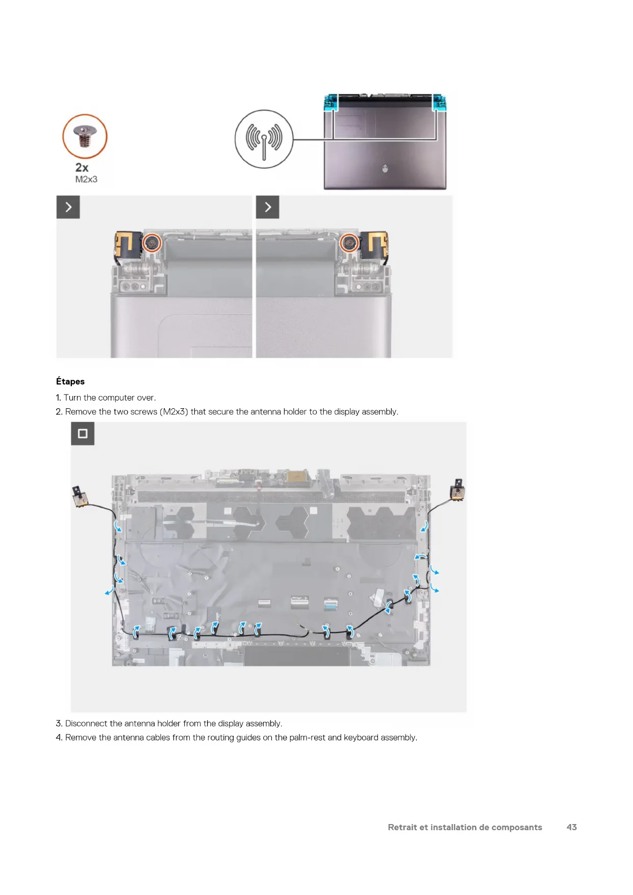
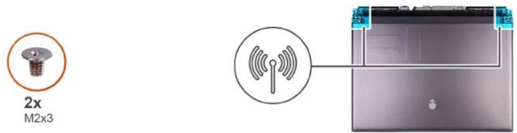
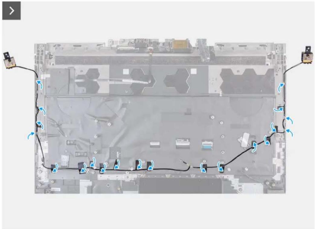
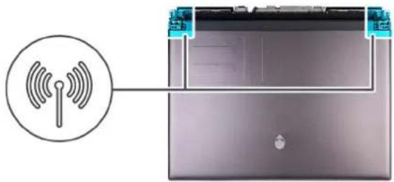
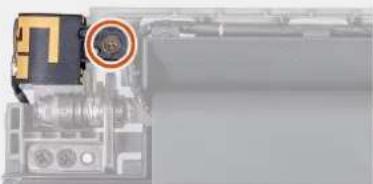
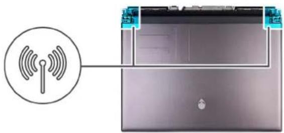
The following image(s) indicate the location of the antennas and provides a visual representation of the removal procedure.
Étapes
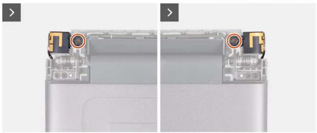
- Turn the computer over.
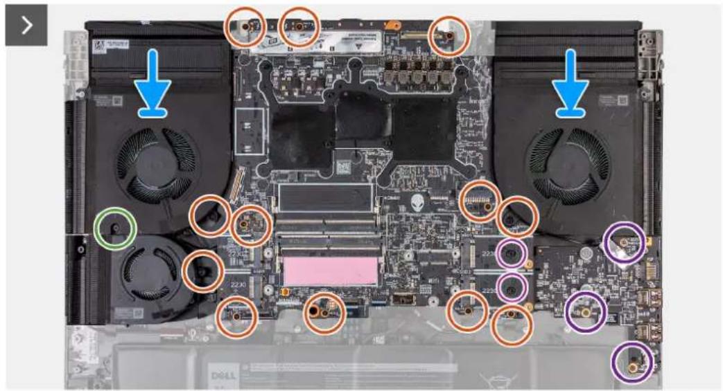
- Remove the two screws (M2x3) that secure the antenna holder to the display assembly.
- Disconnect the antenna holder from the display assembly.
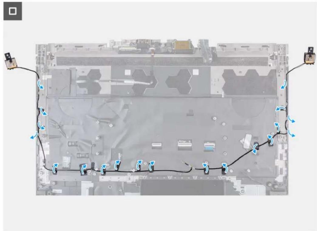
- Remove the antenna cables from the routing guides on the palm-rest and keyboard assembly.
Installing the antennas
Prérequis
If you are replacing a component, remove the existing component before performing the installation process.
The following image(s) indicate the location of the antennas and provides a visual representation of the installation procedure.
Étapes
- Route the antenna cables through the routing guides on the palm-rest and keyboard assembly.
2x
M2x3


- Align the screw holes on the antenna holder with the screw holes on the display assembly.
- Replace the two screws (M2x3) that secure the antenna holder to the display assembly.
- Turn over the computer.
Étapes suivantes
- Follow the procedure from step 6 to step 25 in Installing the system board.
- Install the top heat-sink.
- Install the USB Type-C board.
- Install the rear-I/O cover.
- Install the wireless card.
- Install the M.2 2230 solid-state drive in slot three and four.
- Install the M.2 2280 solid-state drive or M.2 2230 solid-state drive in slot one and two, whichever applicable.
- Install the memory module.
- Install the battery.
- Install the base cover.
- Follow the procedure in After working inside your computer.
Assemblage d'écran
Removing the display assembly
Préquiés
- Follow the procedure in Before working inside your computer.
- Remove the base cover.
- Remove the rear-I/O cover.
The following image(s) indicate the location of the display assembly and provides a visual representation of the removal procedure.
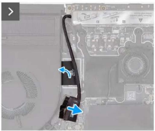
Étapes
- Disconnect the rear I/O board cable from the system board.
- Peel the tapes securing the rear I/O board cable to the system board.
- Remove the I/O board cable through the routing on the fan and palm-rest and keyboard-assembly.
- Peel the tape securing the camera cable to the system board.
- Open the latch and disconnect the camera cable from the system board.
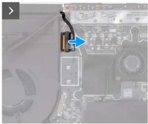
- Peel the tape that secures the display-cable connector latch to the system board.
- Open the latch and disconnect the display cable from the system board.
- Turn the computer over.
2x
M2x3

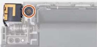


- Remove the two screws (M2x3) that secure the antenna holder to the display assembly.
8x
M2.5x5

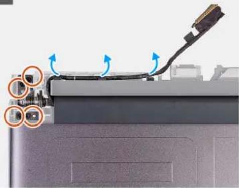

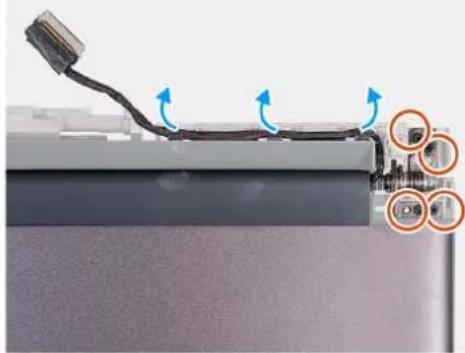
- Peel the display cable off the system board and remove the display cable from the slot on the palm-rest and keyboard assembly.
- Remove the display cable and camera cable from the routing guides on the display assembly.
- Remove the eight screws (M2.5x5) that secure the display assembly to the palm-rest and keyboard assembly.
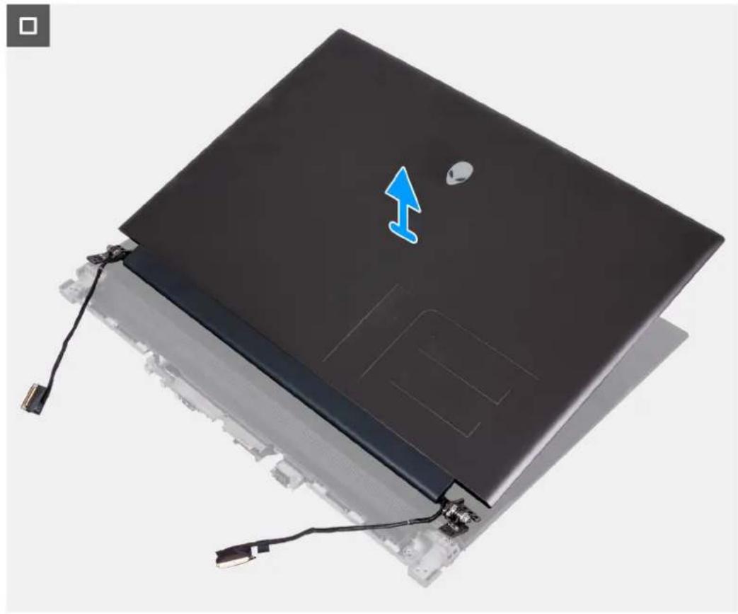
13. Lift the display assembly off the palm-rest and keyboard assembly.
Installing the display assembly
Prérequis
If you are replacing a component, remove the existing component before performing the installation process.
The following image(s) indicate the location of the antennas and provides a visual representation of the installation procedure.
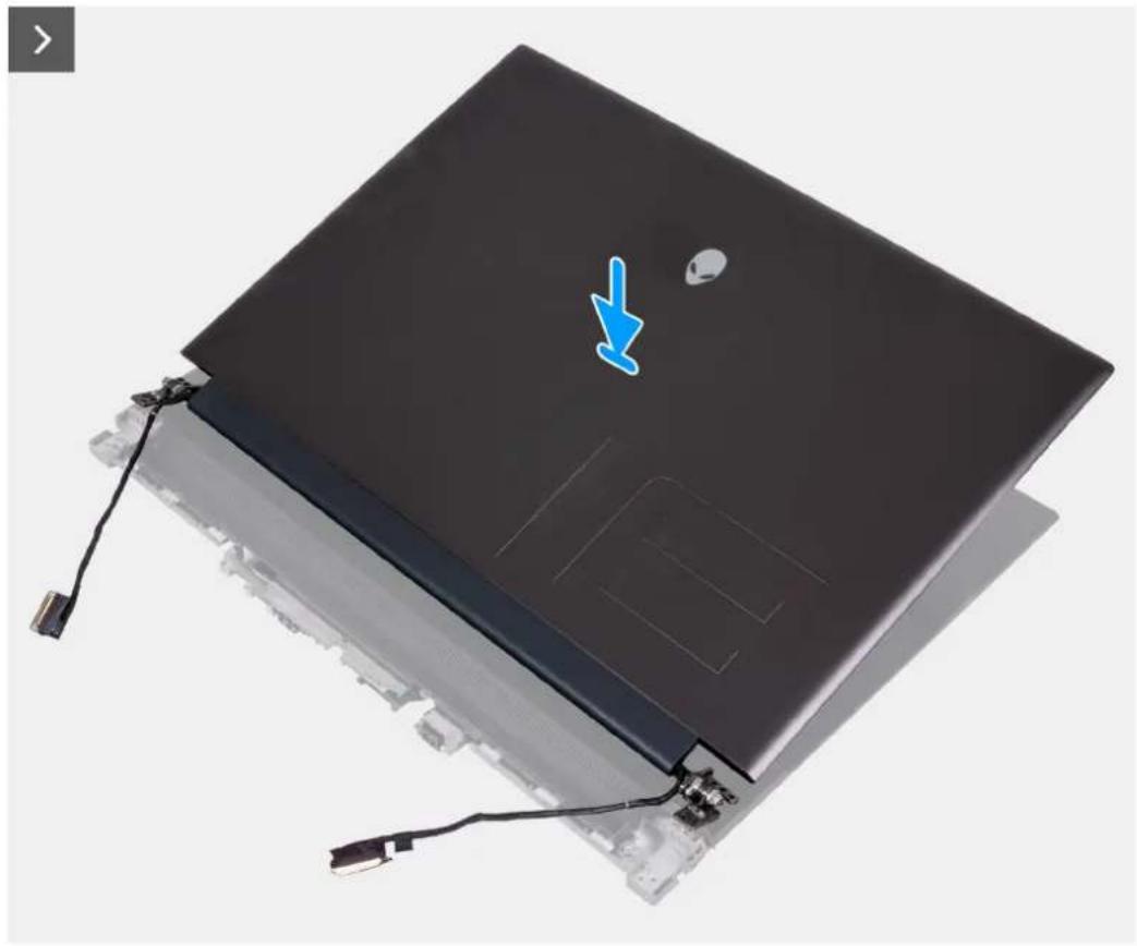
Étapes
- Place the display assembly on the palm-rest and keyboard assembly.
- Route the display cable and camera cable on the routing guides on the display assembly.
8x

M2.5x5
- Align the screw holes on the display assembly to the palm-rest and keyboard assembly.
- Replace the eight screws (M2.5x5) that secure display assembly to the palm-rest and keyboard assembly.
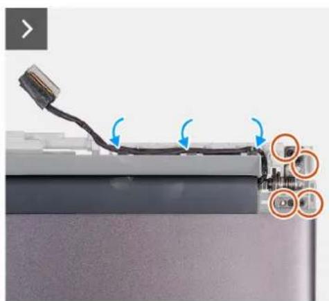
2x
M2x3


- Align the screw holes on the antenna holder with the screw holes on the display assembly.
- Replace the two screws (M2x3) that secure the antenna holder to the display assembly.
- Turn over the computer.
- Adhere the display cable to the system board.
- Connect the display cable to the system board and close the latch to secure the cable.
- Adhere the tape that secures the display-cable connector latch to the system board.
- Connect the camera cable to the system board.
- Adhere the tape securing the rear I/O board cable to the system board.
- Connect the rear I/O board cable through the routing on the fan and palm-rest and keyboard-assembly.
Étapes suivantes
- Install the rear-I/O cover.
- Install the base cover.
- Follow the procedure in After working inside your computer.
Removing the system board
Prérequis
- Follow the procedure in Before working inside your computer.
- Remove the base cover.
- Remove the memory module.
- Remove the M.2 2230 solid-state drive in slot three and four.
- Remove the M.2 2280 solid state drive or M.2 2230 solid-state drive in slot one and two, whichever applicable.
- Remove the wireless card.
- Remove the small fan.
- Remove the rear-I/O cover.
- Remove the top heat-sink.
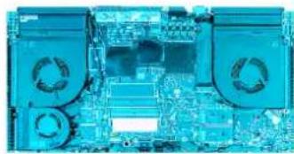
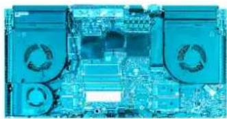
The following image indicates the connectors on your system board.
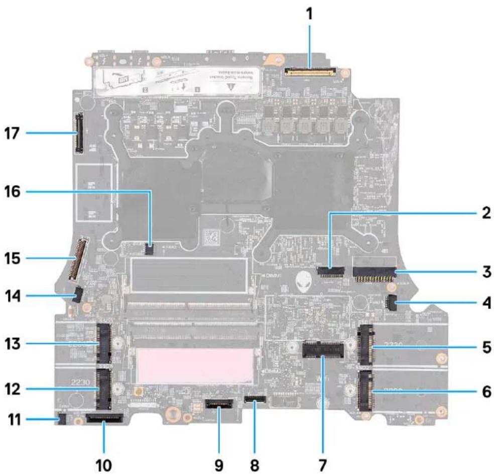
- Display cable 2. Alien head LED-cable
- Power-adapter port cable 4. Right-fan cable
- M.2 card slot for solid-state drive 16. M.2 card slot for solid-state drive 2
- Wireless-card slot 8. Touchpad connector
- Keyboard controller and keyboard backlight 10. Left I/O board cable
- Left-fan cable 112. M.2 card slot for solid-state drive 4
- M.2 card slot for solid-state drive 3 14. Left-fan cable 2
- Rear I/O board cable 16. Left-fan cable 3
- Camera cable

REMARQUE : Computers shipped with NVIDIA GeForce RTX 4080/4090 graphics card have two M.2 2230 and two M.2 2280 solid-state drive slots, whereas computers shipped with NVIDIA GeForce RTX 4050/4060/4070 graphics card have only two M.2 2280 solid-state drive slots.
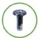
The following image(s) indicate the location of the system board and provides a visual representation of the removal procedure.
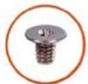
1x
M2x6
12x
M2x4
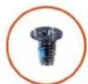
3x
M2x3
2x
M3x7.65,#2
Étapes
- Disconnect the rear I/O board cable from the system board.
- Peel the tapes securing the rear I/O board cable to the system board.
- Peel the tape securing the camera cable to the system board.
- Open the latch and disconnect the camera cable from the system board.
- Peel the tape that secures the display-cable connector latch to the system board.
- Open the latch and disconnect the display cable from the system board.
- Disconnect the right-fan cable from the system board.
- Disconnect the speaker cable from the system board.
- Disconnect the two left-fan cables from the system board.
- Open the latch and disconnect the left I/O board cable from the system board.
- Open the latch and disconnect the keyboard-controller board and keyboard backlight cable from the system board.
- Open the latch and disconnect the touchpad from the system board.
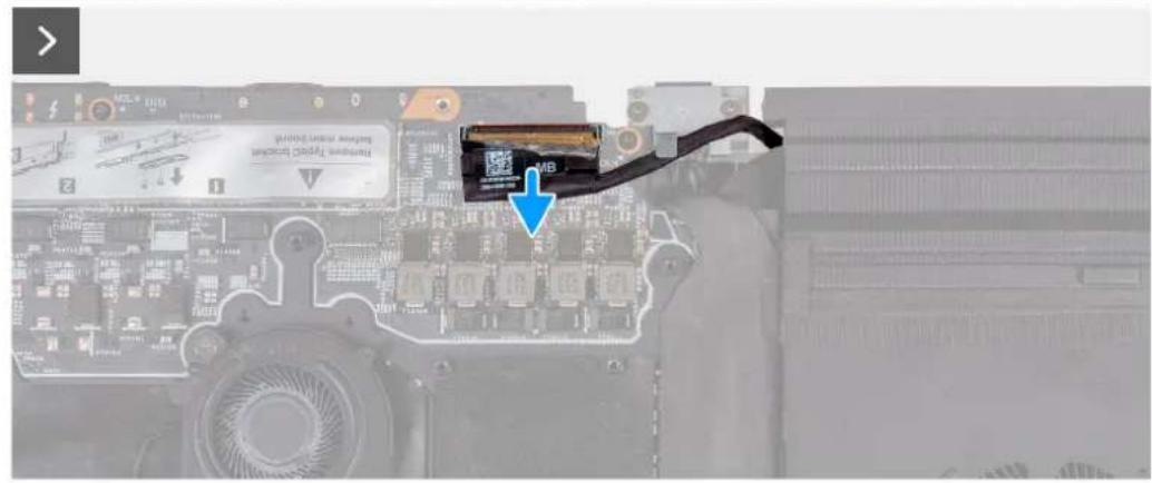
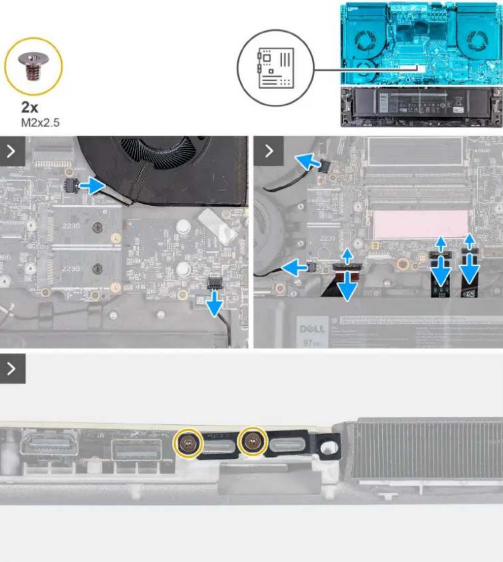
- Remove the two screws (M2x2.5) that secure the Type-C bracket to the system board.

- Lift the Type-C bracket off the system board.
- Disconnect the power-adapter port-cable from the system board.
- Peel the power-adapter port-cable from the system board.
- Remove the three screws (M2x3) that secure the audio board to the palm-rest and keyboard assembly.
- Remove the one screw (M2x6) that secures the left fan to the palm-rest and keyboard assembly.
- Remove the twelve screws (M2x4) that secure the system board to the palm-rest and keyboard assembly.
i REMARQUE : Remove the two screws (M3x7.65, #2) from the M.2 2230 SSD slots on the system board. This step is applicable only for the computers shipped with M.2 2230 solid-state drives.
- After performing all the above steps, you are left with the system board.
- Lift and turn the system board over.
- Remove the heat-sink assembly.
- Remove the audio board.
- Remove the USB Type-C board.
Installing the system board
Prérequis
If you are replacing a component, remove the existing component before performing the installation process.
The following image indicates the connectors on your system board.

- Display cable 2. Alien head LED-cable
- Power-adapter port cable 4. Right-fan cable
- M.2 card slot for solid-state drive 16. M.2 card slot for solid-state drive 2
- Wireless-card slot 8. Touchpad connector
- Keyboard controller and keyboard backlight 10. Left I/O board cable
- Left-fan cable 112. M.2 card slot for solid-state drive 4
- M.2 card slot for solid-state drive 3 14. Left-fan cable 2
- Rear I/O board cable 16. Left-fan cable 3
- Camera cable

REMARQUE : Computers shipped with NVIDIA GeForce RTX 4080/4090 graphics card have two M.2 2230 and two M.2 2280 solid-state drive slots, whereas computers shipped with NVIDIA GeForce RTX 4050/4060/4070 graphics card have only two M.2 2280 solid-state drive slots.
The following image(s) indicate the location of the system board and provides a visual representation of the installation procedure.
Étapes
- Turn the system board over.
- Install the heat-sink assembly.
- Install the audio board.
- Install the USB Type-C board.
- Turn the system-board assembly over.
- Using the alignment posts, place the system-board assembly on the palm-rest and keyboard assembly.
- Replace the twelve screws (M2x4) that secure the system board to the palm-rest and keyboard assembly.
i REMARQUE : Replace the two screws (M3x7.65, #2) that secure the M.2 2230 SSD slots on the system board. This step is applicable only for the computers shipped with M.2 2230 solid-state drives.
- Replace the one screw (M2x6) that left fan to the palm-rest and keyboard assembly.
- Replace the three screws (M2x3) that secures the audio board to the palm-rest and keyboard assembly.
- Adhere the power-adapter port-cable to the system board.
- Connect the power-adapter port-cable to the system board.

- Connect the speaker cable to the system board.
- Connect the right-fan cable to the system board.
- Connect the two left-fan cables to the system board.
- Connect the left I/O board cable to the system board and close the latch to secure the cable.
- Connect the keyboard-controller board and keyboard backlight cable to the system board and close the latch to secure the cable.
- Connect the touchpad to the system board and close the latch to secure the cable.
- Align the screw holes on the Type-C bracket with the screw holes on the palm-rest and keyboard assembly.
- Place the Type-C bracket on the system board.
- Replace the two screws (M2x2.5) that secure the Type-C bracket to the system board.
1x
M2x6
12x
M2x4
3x
M2x3
2x
M3x7.65,#2

- Connect the display cable to the system board and close the latch to secure the cable.
- Adhere the tape that secures the display-cable connector latch to the system board.
- Connect the camera cable to the system board.
- Adhere the tape securing the camera cable to the system board to secure the cable.
- Connect the rear I/O board cable to the system board.
- Adhere the tapes securing the rear I/O board cable to the system board.
Étapes suivantes
- Install the small fan.
- Install the top heat-sink.
- Install the rear-1/O cover.
- Install the wireless card.
- Install the M.2 2230 solid-state drive in slots three and four.
- Install the M.2 2280 solid-state drive or M.2 2230 solid-state drive in slots one and two, whichever applicable.
- Install the memory module.
- Install the base cover.
- Follow the procedure in After working inside your computer.
Removing the audio board
Prérequis
- Follow the procedure in Before working inside your computer.
- Remove the base cover.
- Remove the memory module.
- Remove the M.2 2230 solid-state drive in slot three and four.
- Remove the M.2 2280 solid state drive or M.2 2230 solid-state drive in slot one and two, whichever applicable.
- Remove the wireless card.
- Remove the rear-I/O cover.
- Remove the top heat-sink.
- Follow the procedure from step 1 to step 16 in Removing the system board.
REMARQUE : The system board can be removed and installed along with the audio board, small fan, and heat sink-assembly. This simplifies the removal and installation procedure and avoids breaking the thermal bond between the system board and heat sink.
The following image(s) indicate the location of the audio board and provides a visual representation of the removal procedure.

2x
M2x3
Étapes
- Turn the system-board assembly over.
- Remove the two screws (M2x3) that secure the audio board to the system-board assembly.
- Slide and remove the audio board from the system-board assembly.
Installing the audio board
Préquis
If you are replacing a component, remove the existing component before performing the installation process.
The following image(s) indicate the location of the audio board and provides a visual representation of the installation procedure.
2x
M2x3
Étapes
- Connect the audio board to the system-board assembly.
- Align the screw holes on the audio board with the screw holes on the system-board assembly.
- Replace the two screws (M2x3) that secure the audio board to the system-board assembly.
- Turn the system-board assembly over.
Étapes suivantes
- Follow the procedure from step 6 to step 25 in Installing the system board.
- Install the top heat-sink.
- Install the rear-I/O cover.
- Install the wireless card.
- Install the M.2 2230 solid-state drive in slot three and four.
- Install the M.2 2280 solid-state drive or M.2 2230 solid-state drive in slot one and two, whichever applicable.
- Install the memory module.
- Install the base cover.
- Follow the procedure in After working inside your computer.
Carte USB C
Removing the USB Type-C board
Prérequis
- Follow the procedure in Before working inside your computer.
- Remove the base cover.
- Remove the battery.
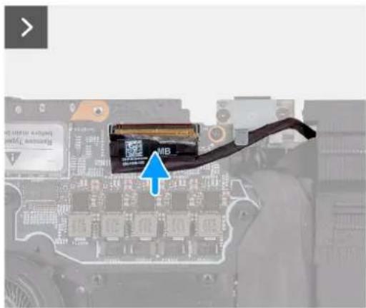
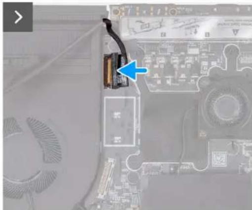
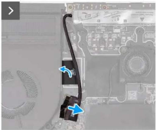
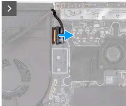
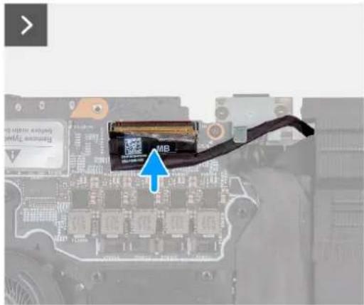
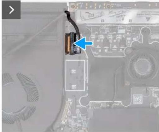
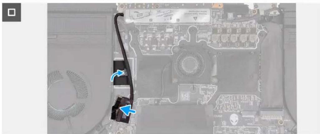
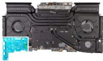
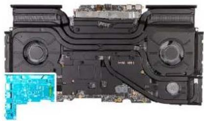
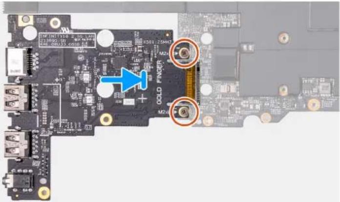
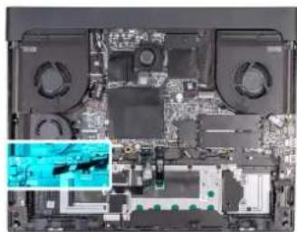
The following image(s) indicate the location of the USB Type-C board and provides a visual representation of the removal procedure.

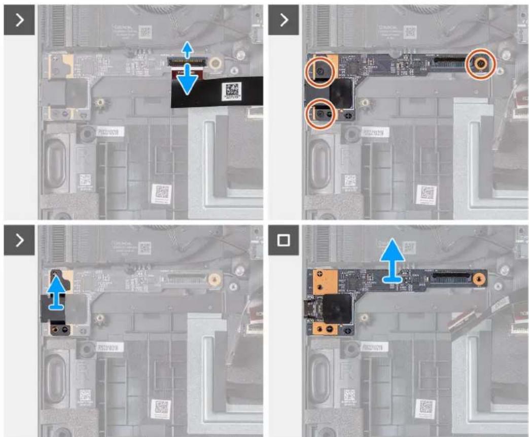
Étapes
- Open the latch and disconnect the USB Type-C I/O board cable connector from system-board assembly.
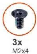
- Remove the three screws (M2x4) that secure the USB Type-C board to the system-board assembly.
- Lift the USB Type-C board shield from the left side.
- Lift the USB Type-C I/O board from the system-board assembly.
Installing the USB Type-C board
Prérequis
If you are replacing a component, remove the existing component before performing the installation process.
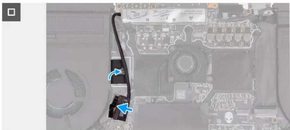
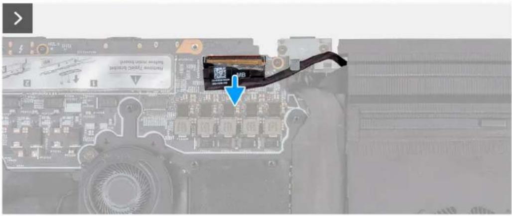
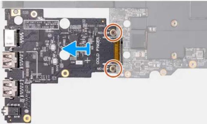
The following image(s) indicate the location of the USB Type-C board and provides a visual representation of the installation procedure.
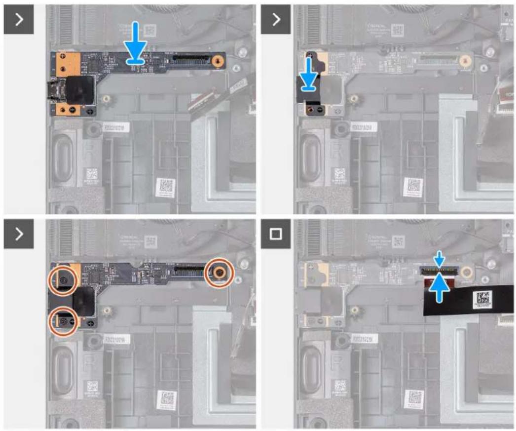
Étapes
- Align the USB Type-C board with the screw holes on the system-board assembly.
- Align the USB Type-C shield on the left side with the screw holes on the system-board assembly.
- Replace the three screws (M2x4) that secure the USB Type-C board to the system-board assembly.
- Connect the USB Type-C I/O board cable connector to the system-board assembly and close the latch to secure the cable.
Étapes suivantes
- Install the battery.
- Install the base cover.
- Follow the procedure in After working inside your computer.
Removing the power button
Prérequis
- Follow the procedure in Before working inside your computer.
- Remove the base cover.
- Remove the battery.
- Remove the memory module.
- Remove the M.2 2230 solid-state drive in slot three and four.
- Remove the M.2 2280 solid state drive or M.2 2230 solid-state drive in slot one and two, whichever applicable.
- Remove the wireless card.
- Remove the rear-I/O cover.
- Remove the top heat-sink.
- Follow the procedure from step 1 to step 16 in Removing the system board.

REMARQUE : The system board can be removed and installed along with the audio board, small fan, and heat sink-assembly. This simplifies the removal and installation procedure and avoids breaking the thermal bond between the system board and heat sink.
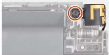
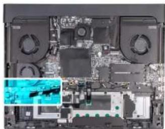
The following image(s) indicate the location of the power button and provides a visual representation of the removal procedure.
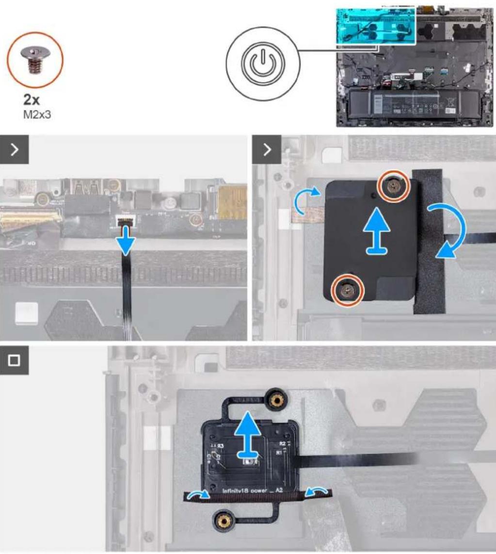
Étapes
- Open the latch and disconnect the power-button cable from the palm-rest and keyboard assembly.
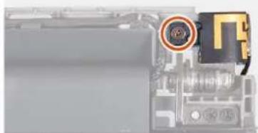
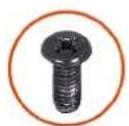
- Remove the two screws (M2x3) that secure the power-button bracket to the palm-rest and keyboard assembly.
- Peel the tapes securing the power-button bracket to the palm-rest and keyboard assembly.
- Lift the power-button bracket off the power button.
- Peel the tape securing the power button to the palm-rest and keyboard assembly.
- Lift the power button, along with its cable, off the palm-rest and keyboard assembly.
Installing the power button
Prérequis
If you are replacing a component, remove the existing component before performing the installation process.
The following image(s) indicate the location of the power button and provides a visual representation of the installation procedure.
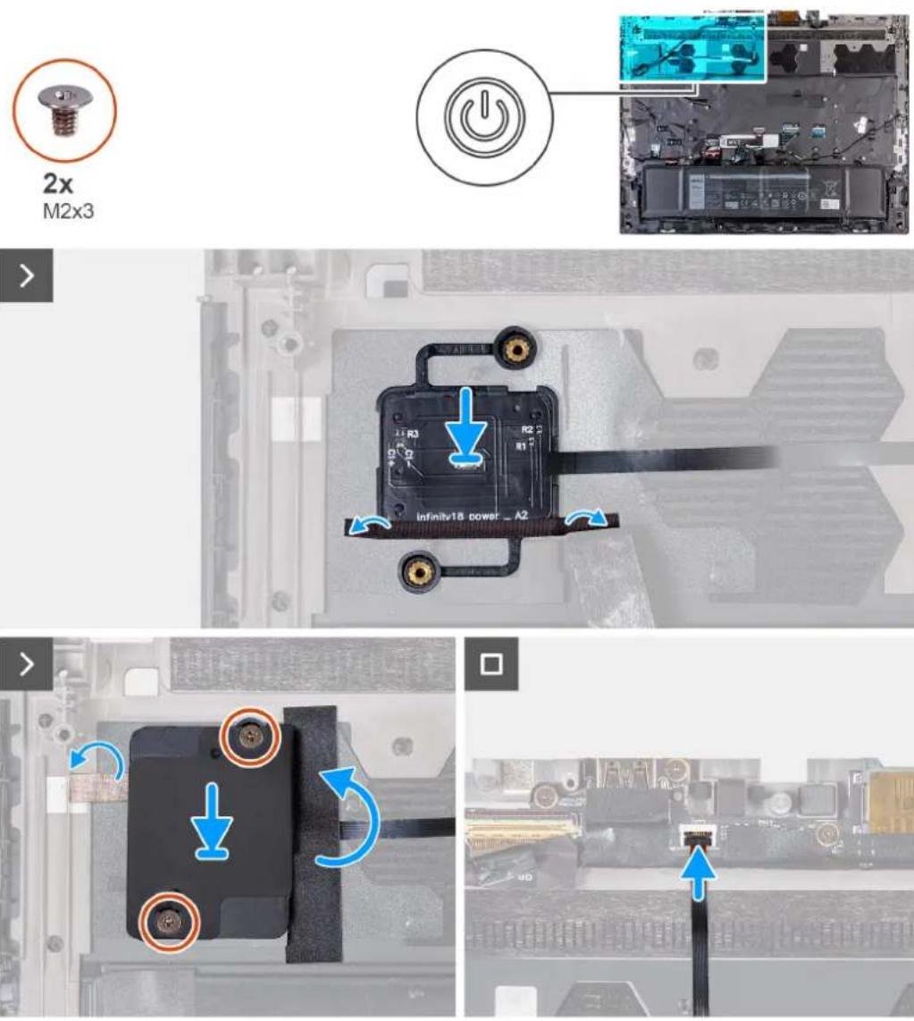
Étapes
- Align and place the power button, along with its cable, into the slot on the palm-rest and keyboard assembly.
- Adhere the tape securing the power button on the palm-rest and keyboard assembly.
- Align the screw holes on the power-button bracket with the screw holes on the palm-rest and keyboard assembly.
- Replace the two screws (M2x3) that secure the power-button bracket to the palm-rest and keyboard assembly and adhere the tape.
- Adhere the tapes securing the power-button bracket to the palm-rest and keyboard assembly.
- Connect the power-button cable and close the latch to secure the cable.
Étapes suivantes
- Follow the procedure from step 6 to step 25 in Installing the system board.
- Install the top heat-sink.
- Install the rear-I/O cover.
- Install the wireless card.
- Install the M.2 2230 solid-state drive in slot three and four.
- Install the M.2 2280 solid-state drive or M.2 2230 solid-state drive in slot one and two, whichever applicable.
- Install the memory module.
- Install the battery.
- Install the base cover.
- Follow the procedure in After working inside your computer.
Removing the palm-rest and keyboard assembly
Prérequis
- Follow the procedure in Before working inside your computer.
- Remove the base cover.
- Remove the memory module.
- Remove the M.2 2230 solid-state drive in slot three and four.
- Remove the M.2 2280 solid state drive or M.2 2230 solid-state drive in slot one and two, whichever applicable.
- Remove the rear-I/O cover.
- Remove the top heat-sink.
- Remove the wireless card.
- Remove the battery.
- Remove the speakers.
- Remove the USB Type-C board.
- Remove the power-adapter port.
- Remove the touchpad.
- Remove the antennas
- Remove the display assembly.
- Remove the keyboard-controller board.
- Follow the procedure from step 1 to step 16 in Removing the system board.

REMARQUE : The system board can be removed and installed along with the audio board, small fan, and heat sink-assembly. This simplifies the removal and installation procedure and avoids breaking the thermal bond between the system board and heat sink.
- Remove the power button.
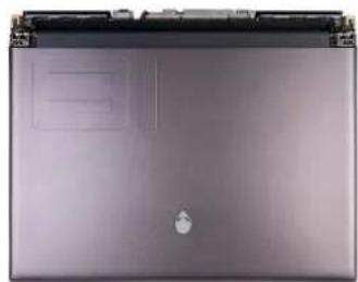
The following image(s) indicate the location of the palm-rest and keyboard assembly and provides a visual representation of the removal procedure.
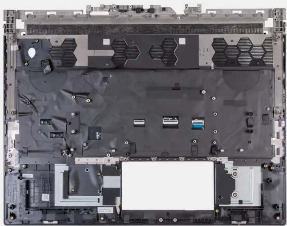
Étapes
After performing the pre-requisites you are left with the palm-rest and keyboard assembly.

REMARQUE : Ensure that the solid-state drive mounts are removed from the old palm-rest and keyboard assembly before installing the new palm-rest and keyboard assembly. These solid-state drive mounts will be installed into the new palm-rest and keyboard assembly.
Installing the palm-rest and keyboard assembly
Prérequis
If you are replacing a component, remove the existing component before performing the installation process.
The following image(s) indicate the location of the palm-rest and keyboard assembly and provides a visual representation of the installation procedure.
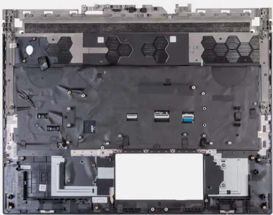
Étapes
Place the palm-rest and keyboard assembly on a flat and clean surface and perform the post-requisites to install the palm-rest and keyboard assembly.

REMARQUE : Install the solid-state drive mounts from the old palm-rest and keyboard assembly into the new palm-rest and keyboard assembly.
Étapes suivantes
- Install the power button.
- Follow the procedure from step 6 to step 25 in Installing the system board.
- Install the keyboard-controller board.
- Install the display assembly.
- Install the antennas.
- Install the touchpad.
- Install the power-adapter port.
- Install the USB Type-C board.
- Install the speakers.
- Install the battery.
- Install the top heat-sink.
- Install the rear-I/O cover.
- Install the wireless card.
- Install the M.2 2280 solid-state drive or M.2 2230 solid-state drive in slot one and two, whichever applicable.
- Install the M.2 2230 solid-state drive in slot three and four.
- Install the memory module.
- Install the base cover.
- Follow the procedure in After working inside your computer.
Power and battery-status light
The power and battery status light indicates the power and battery status of the computer. These are the power states:
Solid white:Power adapter is connected and the battery has more than 5% charge.
Amber: Computer is running on battery and the battery has less than 5% charge.
Off:
- Power adapter is connected, and the battery is fully charged.
- Computer is running on battery, and the battery has more than 5% charge.
- Computer is in sleep state, hibernation, or turned off.
The power and battery-status light may also blink red or blue according to pre-defined "beep codes" indicating various failures.
For example, the power and battery-status light blinks red two times followed by a pause, and then blinks blue three times followed by a pause. This 2,3 pattern continues until the computer is turned off, indicating no memory or RAM is detected.
The following table shows different power and battery-status light patterns and associated problems.

REMARQUE : The following diagnostic light codes and recommended solutions are intended for Dell service technicians to troubleshoot problems. You should only perform troubleshooting and repairs as authorized or directed by the Dell technical support team. Damage due to servicing that is not authorized by Dell is not covered by your warranty.
Tableau 21. Diagnostic-light LED codes
Diagnostic light codes Problem description
1,1 TPM detection failure
1,2 Unrecoverable SPI Flash Failure
1,3 Short in hinge cable tripped OCP1 (camera/ touchpad)
1,4 Short in hinge cable tripped OCP2 (display)
1,5 EC unable to program i-Fuse
1,6 Generic catch-all for ungraceful EC code flow errors
2.1 Processor failure
2,2 System board: BIOS or ROM (Read-Only Memory) failure
2,3 No memory or RAM (Random-Access Memory) detected
2,4 Memory or RAM (Random-Access Memory) failure
2,5 Invalid memory installed
2,6 System-board or chipset error
2,7 Display failure - SBIOS message
2,8 Display failure - EC detection of power rail failure
3,1 RTC power failure
3,2 PCI, video card/chip failure
3,3 Recovery image not found
3,4 Recovery image found but invalid
3.5 Power-rail failure
3,6 System BIOS Flash incomplete
Tableau 21. Diagnostic-light LED codes (suite)
Diagnostic light codes Problem description
3,7 Management Engine (ME) error
Diagnostics SupportAssist
SupportAssist OS Recovery.