
15 R2 - Laptop ALIENWARE - Free user manual and instructions
Find the device manual for free 15 R2 ALIENWARE in PDF.


| Product Type | Gaming Laptop |
| Brand | Alienware |
| Model | 15 R2 |
| Dimensions (W x D x H) | 389 x 305 x 25.4 mm |
| Weight | 3.5 kg |
| Display | 15.6-inch Full HD (1920x1080) IPS |
| Processor | Intel Core i7-6700HQ (2.6 GHz, up to 3.5 GHz) |
| Memory | Up to 32 GB DDR4 (2 slots) |
| Storage | 1 TB HDD + 256 GB SSD (M.2 NVMe) |
| Graphics | NVIDIA GeForce GTX 1060 (6 GB GDDR5) |
| Operating System | Windows 10 Home |
| Ports | 3x USB 3.0, 1x USB 3.1 Type-C, 1x HDMI, 1x Mini DisplayPort, 1x Ethernet, 1x Headphone, 1x Mic |
| Wireless | 802.11ac Wi-Fi + Bluetooth 4.2 |
| Power Supply | 180 W AC adapter |
| Battery | 6-cell 68 Wh lithium-ion |
| Cooling | Alienware Cyro-Tech cooling (dual fans, copper heat pipes) |
| Keyboard | RGB backlit Alienware keyboard |
| Maintenance & Cleaning | Use a soft dry cloth; avoid liquids. Clean vents regularly with compressed air. |
| Security | TPM 2.0, Kensington lock slot, fingerprint reader (optional) |
| Spare Parts & Repairability | RAM, storage, and Wi-Fi card user-accessible. Battery and display replaceable by technician. |
| Warranty | 1 year limited hardware warranty |
Frequently Asked Questions - 15 R2 ALIENWARE
User questions about 15 R2 ALIENWARE
0 question about this device. Answer the ones you know or ask your own.
Ask a new question about this device
Download the instructions for your Laptop in PDF format for free! Find your manual 15 R2 - ALIENWARE and take your electronic device back in hand. On this page are published all the documents necessary for the use of your device. 15 R2 by ALIENWARE.
USER MANUAL 15 R2 ALIENWARE
Alienware 15 Service Manual
Notes, Cautions, and Warnings

NOTE: A NOTE indicates important information that helps you make better use of your computer.

CAUTION: A CAUTION indicates either potential damage to hardware or loss of data and tells you how to avoid the problem.

WARNING: A WARNING indicates a potential for property damage, personal injury, or death.
Copyright © 2015 Dell Inc. All rights reserved. This product is protected by U.S. and international copyright and intellectual property laws. Dell™ and the Dell logo are trademarks of Dell Inc. in the United States and/or other jurisdictions. All other marks and names mentioned herein may be trademarks of their respective companies.
2015 - 01
Rev. A00
Contents
Before working inside your computer.... 12
Before you begin 12
Safety instructions.... 12
Recommended tools....14
After working inside your computer.... 15
Removing the base panel.... 16
Procedure....16
Replacing the base panel....19
Procedure....19
Removing the memory modules....20
Prerequisites....20
Procedure....20
Replacing the memory modules....22
Procedure....22
Post-requisites....23
Removing the solid-state drives....24
Prerequisites....24
Procedure....24
Replacing the solid-state drives....26
Procedure....26
Post-requisites....26
Removing the hard drive.... 27
Prerequisites....27
Procedure....28
Replacing the hard drive.... 32
Procedure....32
Post-requisites....32
Removing the wireless card.... 33
Prerequisites....33
Procedure....33
Replacing the wireless card....35
Procedure....35
Post-requisites....35
Removing the palm rest.... 36
Prerequisites....36
Procedure....36
Replacing the palm rest....43
Procedure....43
Post-requisites....43
Removing the touch pad....44
Prerequisites....44
Procedure....44
Replacing the touch pad.... 48
Procedure....48
Post-requisites.... 48
Removing the keyboard....49
Prerequisites....49
Procedure....49
Replacing the keyboard....55
Procedure....55
Post-requisites....55
Removing the power-button board.... 56
Prerequisites....56
Procedure....56
Replacing the power-button board....59
Procedure....59
Post-requisites....59
Removing the status-light board.... 60
Prerequisites....60
Procedure....61
Replacing the status-light board.... 63
Procedure....63
Post-requisites....63
Removing the I/O board....64
Prerequisites....64
Procedure....64
Replacing the I/O board....66
Procedure....66
Post-requisites....66
Removing the speakers.... 67
Prerequisites....67
Procedure....67
Replacing the speakers....70
Procedure....70
Post-requisites....70
Removing the front AlienFX LED boards....71
Prerequisites....71
Procedure....71
Replacing the front AlienFX LED board.... 73
Procedure....73
Post-requisites....73
Removing the hinge covers.... 74
Prerequisites....74
Procedure....74
Replacing the hinge covers....76
Procedure....76
Post-requisites....76
Removing the display assembly.... 77
Prerequisites....77
Procedure....77
Replacing the display assembly.... 81
Procedure....81
Post-requisites....81
Removing the display bezel.... 83
Prerequisites....83
Procedure....83
Replacing the display bezel.... 87
Procedure....87
Post-requisites....87
Removing the display panel.... 88
Prerequisites....88
Procedure....88
Replacing the display panel....91
Procedure....91
Post-requisites....91
Removing the display hinges....92
Prerequisites....92
Procedure....92
Replacing the display hinges.... 94
Procedure....94
Post-requisites....94
Removing the display back-cover.... 95
Prerequisites....95
Procedure....95
Replacing the display back-cover....98
Procedure....98
Post-requisites....98
Removing the camera....99
Prerequisites....99
Procedure....100
Replacing the camera....102
Procedure....102
Post-requisites....102
Removing the Alienware AlienHead LED board.. 103
Prerequisites....103
Procedure....103
Replacing the Alienware AlienHead LED board...106
Procedure....106
Post-requisites....106
Removing the display-panel AlienFX LEDs...... 107
Prerequisites....107
Procedure....108
Replacing the display-panel AlienFX LEDs...... 110
Procedure....110
Post-requisites....110
Removing the logo board....111
Prerequisites....111
Procedure....111
Replacing the logo board.... 113
Procedure....113
Post-requisites....113
Removing the system board.... 114
Prerequisites....114
Procedure....114
Replacing the system board....118
Procedure....118
Post-requisites....119
Removing the heat-sink assembly....120
Prerequisites....120
Procedure....120
Replacing the heat-sink assembly.... 122
Procedure....122
Post-requisites....122
Removing the fans....123
Prerequisites....123
Procedure....123
Replacing the fans.... 125
Procedure....125
Post-requisites....125
Removing the power-adapter port....126
Prerequisites.... 126
Procedure....126
Replacing the power-adapter port.... 128
Procedure....128
Post-requisites....128
Removing the coin-cell battery....129
Prerequisites....129
Procedure....129
Replacing the coin-cell battery.... 131
Procedure....131
Post-requisites....131
Removing the battery....132
Prerequisites....132
Procedure....132
Replacing the battery.... 135
Procedure....135
Post-requisites....135
Removing the computer base.... 136
Prerequisites....136
Procedure....136
Replacing the computer base....138
Procedure....138
Post-requisites....138
BIOS setup program....139
Overview....139
Entering BIOS setup program....139
BIOS setup program options....139
Boot sequence....145
Boot options....145
Changing boot sequence for the current boot.... 146
Changing boot sequence for future boots....146
Flashing the BIOS....148
Getting help and contacting Alienware...... 149
Self-help resources....149
Contacting Alienware....149
Before working inside your computer

CAUTION: To avoid damaging the components and cards, handle them by their edges and avoid touching pins and contacts.

NOTE: The images in this document may differ from your computer depending on the configuration you ordered.
Before you begin
1 Save and close all open files and exit all open applications.
2 Shut down your computer.
- Windows 8.1: On the Start screen, click or tap the power icon Shut down.

- Windows 7: Click or tap Start → Shut down.

NOTE: If you are using a different operating system, see the documentation of your operating system for shut-down instructions.
3 Disconnect your computer and all attached devices from their electrical outlets.
4 Disconnect all cables such as telephone cables, network cables and so on, from your computer.
5 Disconnect all attached devices and peripherals, such as keyboard, mouse, monitor, and so on, from your computer.
6 Remove any media card and optical disc from your computer, if applicable.
Safety instructions
Use the following safety guidelines to protect your computer from potential damage and ensure your personal safety.

WARNING: Before working inside your computer, read the safety information that shipped with your computer. For more safety best practices, see the Regulatory Compliance home page at dell.com/regulatory_compliance.
WARNING: Disconnect all power sources before opening the computer cover or panels. After you finish working inside the computer, replace all covers, panels, and screws before connecting to the power source.
CAUTION: To avoid damaging the computer, make sure that the work surface is flat and clean.
CAUTION: To avoid damaging the components and cards, handle them by their edges and avoid touching pins and contacts.
CAUTION: You should only perform troubleshooting and repairs as authorized or directed by the Dell technical assistance team. Damage due to servicing that is not authorized by Dell is not covered by your warranty. See the safety instructions that shipped with the product or at dell.com/regulatory_compliance.
CAUTION: Before touching anything inside your computer, ground yourself by touching an unpainted metal surface, such as the metal at the back of the computer. While you work, periodically touch an unpainted metal surface to dissipate static electricity, which could harm internal components.
CAUTION: When you disconnect a cable, pull on its connector or on its pull-tab, not on the cable itself. Some cables have connectors with locking tabs or thumb-screws that you must disengage before disconnecting the cable. When disconnecting cables, keep them evenly aligned to avoid bending any connector pins. When connecting cables, make sure that the ports and connectors are correctly oriented and aligned.
CAUTION: To disconnect a network cable, first unplug the cable from your computer and then unplug the cable from the network device.
CAUTION: Press and eject any installed card from the media-card reader.
Recommended tools
The procedures in this document may require the following tools:
- Philips screwdriver
- Plastic scribe
After working inside your computer

CAUTION: Leaving stray or loose screws inside your computer may severely damage your computer.
1 Replace all screws and make sure that no stray screws remain inside your computer.
2 Connect any external devices, peripherals, and cables you removed before working on your computer.
3 Replace any media cards, discs, and any other parts that you removed before working on your computer.
4 Connect your computer and all attached devices to their electrical outlets.
5 Turn on your computer.
Removing the base panel

WARNING: Before working inside your computer, read the safety information that shipped with your computer and follow the steps in Before working inside your computer. After working inside your computer, follow the instructions in After working inside your computer. For more safety best practices, see the Regulatory Compliance home page at dell.com/regulatory_compliance.
Procedure
1 Close the display and turn the computer over.
2 Loosen the captive screws that secure the base panel to the computer base.
3 Using a plastic scribe, gently release the tabs that secure the base panel to the computer base.
4 Slide and remove the base panel from the computer base.

1 computer base 2 captive screws (2)
3 base panel 4 plastic scribe
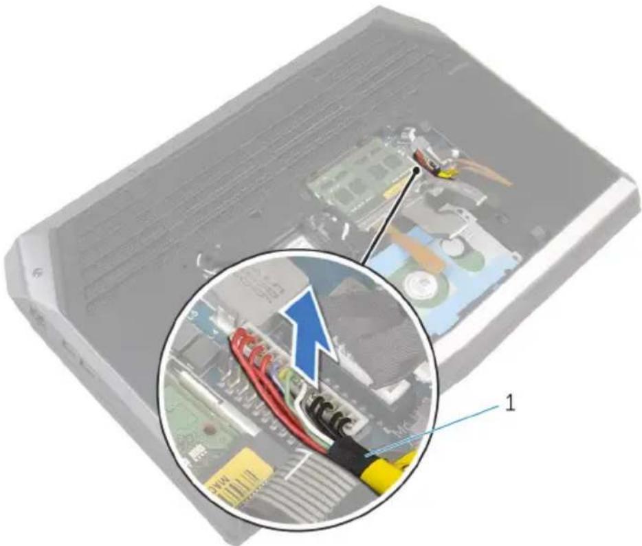
5 Disconnect the battery cable from the system board.
natural_image
Close-up of an electronic device with a magnified inset showing internal components and wiring (no text or symbols visible)1 battery cable
6 Turn the computer over and open the display as far as possible.
7 Press and hold the power button for 4 seconds to ground the system board.
Replacing the base panel

WARNING: Before working inside your computer, read the safety information that shipped with your computer and follow the steps in Before working inside your computer. After working inside your computer, follow the instructions in After working inside your computer. For more safety best practices, see the Regulatory Compliance home page at dell.com/regulatory_compliance.
Procedure
1 Close the display and turn the computer over.
2 Connect the battery cable to the system board.
3 Slide the tabs on the base panel into the slots on the computer base and snap the base panel into place.
4 Tighten the captive screws that secure the base panel to the computer base.
Removing the memory modules

WARNING: Before working inside your computer, read the safety information that shipped with your computer and follow the steps in Before working inside your computer. After working inside your computer, follow the instructions in After working inside your computer. For more safety best practices, see the Regulatory Compliance home page at dell.com/regulatory_compliance.
Prerequisites
Remove the base panel.
Procedure
1 Using your fingertips, carefully spread apart the securing clips on each end of the memory-module slot until the memory module pops up.
2 Slide and remove the memory module from the memory-module slot.

1 securing clips (2) 2 memory modules (2)
3 memory-module slot
Replacing the memory modules

WARNING: Before working inside your computer, read the safety information that shipped with your computer and follow the steps in Before working inside your computer. After working inside your computer, follow the instructions in After working inside your computer. For more safety best practices, see the Regulatory Compliance home page at dell.com/regulatory_compliance.
Procedure
1 Align the notch on the memory module with the tab on the memory-module slot.
2 Slide the memory module firmly into the slot at an angle and press the memory module down until it clicks into place.

NOTE: If you do not hear the click, remove the memory module and reinstall it.

1 securing clips (2) 2 notch
3 tab 4 memory modules (2)
5 memory-module slot
Post-requisites
Replace the base panel.
Removing the solid-state drives

WARNING: Before working inside your computer, read the safety information that shipped with your computer and follow the steps in Before working inside your computer. After working inside your computer, follow the instructions in After working inside your computer. For more safety best practices, see the Regulatory Compliance home page at dell.com/regulatory_compliance.

CAUTION: Solid-state drives are fragile. Exercise care when handling the hard drive.

CAUTION: To avoid data loss, do not remove the solid-state drive while the computer is in sleep or on state.
Prerequisites
Remove the base panel.
Procedure
1 Remove the screw that secures the solid-state drive to the computer base.
2 Slide and remove the solid-state drive from the solid-state drive slot.
1 screw 2 solid-state drive slot 3 solid-state drives (2)
Replacing the solid-state drives

WARNING: Before working inside your computer, read the safety information that shipped with your computer and follow the steps in Before working inside your computer. After working inside your computer, follow the instructions in After working inside your computer. For more safety best practices, see the Regulatory Compliance home page at dell.com/regulatory_compliance.

CAUTION: Solid-state drives are fragile. Exercise care when handling the hard drive.
Procedure
1 Slide the solid-state drive into the solid-state drive slot.
2 Align the screw hole on the solid-state drive with the screw hole on the computer base.
3 Replace the screw that secures the solid-state drive to the computer base.
Post-requisites
Replace the base panel.
Removing the hard drive

WARNING: Before working inside your computer, read the safety information that shipped with your computer and follow the steps in Before working inside your computer. After working inside your computer, follow the instructions in After working inside your computer. For more safety best practices, see the Regulatory Compliance home page at dell.com/regulatory_compliance.

CAUTION: Hard drives are fragile. Exercise care when handling the hard drive.

CAUTION: To avoid data loss, do not remove the hard drive while the computer is in sleep or on state.
Prerequisites
Remove the base panel.
Procedure
1 Remove the keyboard-backlight cable, keyboard cable, and macro-keys cable from the routing guides on the computer base.
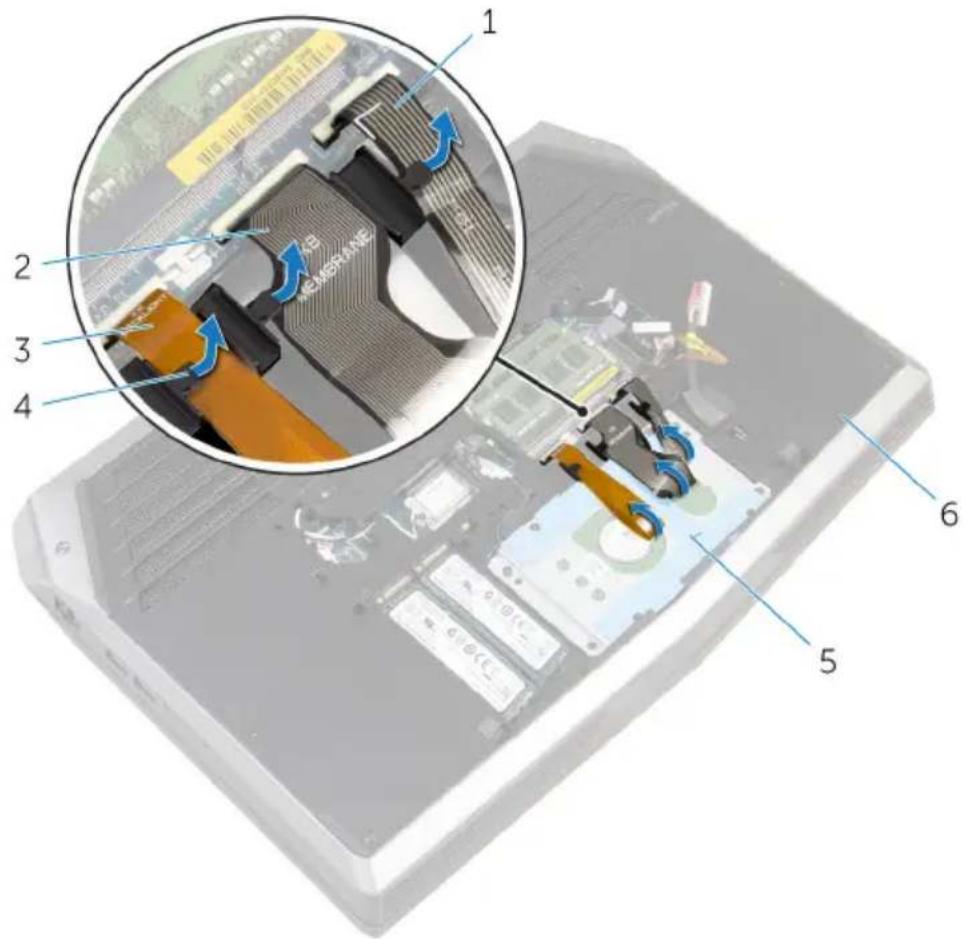
1 macro-keys cable 2 keyboard cable
3 keyboard-backlight cable 4 routing guides (3)
5 hard-drive assembly 6 computer base
2 Remove the screws that secure the hard-drive assembly to the computer base.
3 Using the pull tab, disconnect the hard-drive cable from the system board.
4 Note the hard-drive cable routing and remove the cable from the routing guides on the computer base.
5 Lift and slide the hard-drive assembly off the computer base.
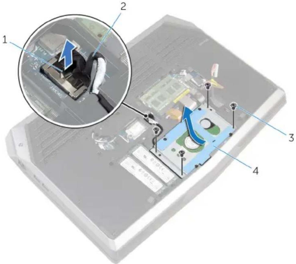
1 pull tab 2 hard-drive cable
3 screws (4) 4 hard-drive assembly
6 Remove the screws that secure the hard-drive bracket to the hard-drive assembly.
7 Lift the hard-drive bracket off the hard-drive assembly.
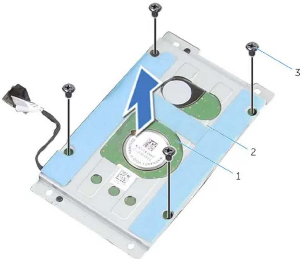
1 hard-drive assembly 2 hard-drive bracket 3 screws (4)
8 Disconnect the interposer from the hard drive.
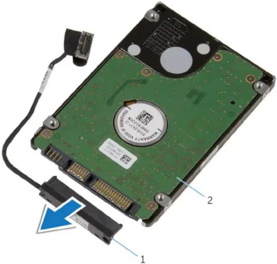
1 interposer 2 hard drive
Replacing the hard drive

WARNING: Before working inside your computer, read the safety information that shipped with your computer and follow the steps in Before working inside your computer. After working inside your computer, follow the instructions in After working inside your computer. For more safety best practices, see the Regulatory Compliance home page at dell.com/regulatory_compliance.

CAUTION: Hard drives are fragile. Exercise care when handling the hard drive.
Procedure
1 Connect the interposer to the hard drive.
2 Align the screw holes on the hard-drive bracket with the screw holes on the hard-drive assembly.
3 Replace the screws that secure the hard-drive bracket to the hard-drive assembly.
4 Slide the hard-drive assembly under the tab on the computer base and align the screw holes on the hard-drive assembly with the screw holes on the computer base.
5 Replace the screws that secure the hard-drive assembly to the computer base.
6 Route the hard-drive cable through the routing guides on the computer base.
7 Connect the hard-drive cable to the system board.
8 Route the keyboard-backlight cable, keyboard cable, and macro-keys cable through the routing guides on the computer base.
Post-requisites
Replace the base panel.
Removing the wireless card

WARNING: Before working inside your computer, read the safety information that shipped with your computer and follow the steps in Before working inside your computer. After working inside your computer, follow the instructions in After working inside your computer. For more safety best practices, see the Regulatory Compliance home page at dell.com/regulatory_compliance.
Prerequisites
Remove the base panel.
Procedure
1 Remove the screw that secures the wireless-card bracket to the system board.
2 Lift the wireless-card bracket off the wireless card.
3 Disconnect the antenna cables from the wireless card.
4 Lift and slide the wireless card out of the wireless-card slot.

1 antenna cables (2) 2 wireless-card bracket
3 screw 4 wireless card
5 wireless-card slot 6 tabs (2)
7 notches (2)
Replacing the wireless card

WARNING: Before working inside your computer, read the safety information that shipped with your computer and follow the steps in Before working inside your computer. After working inside your computer, follow the instructions in After working inside your computer. For more safety best practices, see the Regulatory Compliance home page at dell.com/regulatory_compliance.
Procedure

CAUTION: To avoid damaging the wireless card, do not place any cables under it.
1 Align the notches on the wireless card with the tabs on the wireless-card slot.
2 Slide the wireless-card at an angle into the wireless-card slot.
3 Connect the antenna cables to the wireless card.
A label at the tip of the antenna cables indicates color scheme for the wireless card supported by your computer.
Connectors on the wireless card Antenna-cable sticker color
Auxiliary White
Main Black
4 Press the other end of the wireless card down and align the screw hole on the wireless-card bracket with the screw hole on the system board.
5 Replace the screw that secures the wireless-card bracket to the system board.
Post-requisites
Replace the base panel.
Removing the palm rest

WARNING: Before working inside your computer, read the safety information that shipped with your computer and follow the steps in Before working inside your computer. After working inside your computer, follow the instructions in After working inside your computer. For more safety best practices, see the Regulatory Compliance home page at dell.com/regulatory_compliance.
Prerequisites
1 Remove the base panel.
2 Remove the memory modules.
3 Remove the solid-state drives.
Procedure
1 Remove the keyboard cable, keyboard-backlight cable, and macro-keys cable from the routing guides on the computer base.
2 Lift the latches and disconnect the keyboard-backlight cable, keyboard cable, macro-keys cable, and macro-keys backlight cable from the system board.
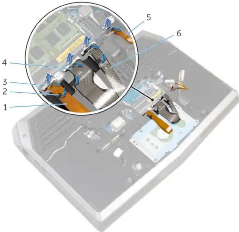
1 keyboard-backlight cable 2 routing guides (3)
3 latches (4) 4 keyboard cable
5 macro-keys backlight cable 6 macro-keys cable
3 Remove the screws that secure the palm-rest assembly to the computer base.

1 screws (15) 2 computer base
4 Turn the computer over and open the display as far as possible.
5 Lift the computer base and rest the display on a clean and flat surface.
6 Push the palm-rest assembly from the release hole to release it from the tabs on the computer base.

1 palm-rest assembly 2 computer base
3 release hole
7 Place the computer in an upright position.
8 Using a plastic scribe, pry up along the edges of the palm-rest assembly.
9 Gently lift the palm-rest assembly and remove the keyboard cable, keyboard-backlight cable, macro-keys cable, and macro-keys backlight cable from the slot on the computer base.

1 palm-rest assembly 2 plastic scribe
10 Carefully turn the palm-rest assembly over and disconnect the power-button board cable from the system board.
11 Lift the palm-rest assembly off the computer base.
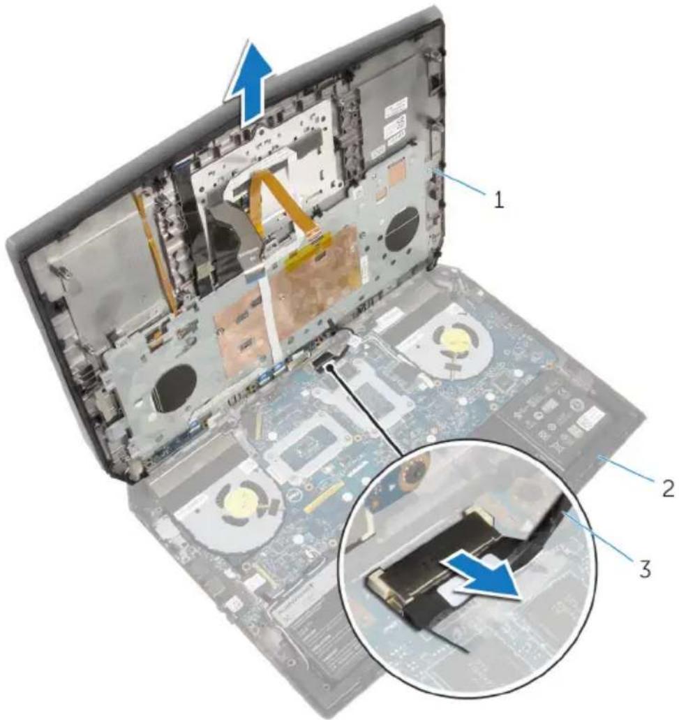
1 palm-rest assembly 2 computer base
3 power-button board cable
12 Turn the palm-rest assembly over.
13 Follow the procedure from step 1 to step 6 in "Removing the keyboard".
14 Follow the procedure from step 1 to step 4 in "Removing the power-button board".
15 Follow the procedure from step 1 to step 3 in "Removing the status-light board".
16 Follow the procedure from step 1 to step 5 in "Removing the touch pad".

natural_image
3D rendering of a rectangular electronic device casing with internal compartments and mounting holes (no text or symbols visible)1 palm-rest assembly
Replacing the palm rest

WARNING: Before working inside your computer, read the safety information that shipped with your computer and follow the steps in Before working inside your computer. After working inside your computer, follow the instructions in After working inside your computer. For more safety best practices, see the Regulatory Compliance home page at dell.com/regulatory_compliance.
Procedure
1 Follow the procedure from step 1 to step 5 in "Replacing the touch pad".
2 Follow the procedure from step 1 to step 3 in "Replacing the status-light board".
3 Follow the procedure from step 1 to step 4 in "Replacing the power-button board".
4 Follow the procedure from step 1 to step 7 in "Replacing the keyboard".
5 Connect the power-button board cable to the system board.
6 Carefully turn the palm-rest assembly over and slide the keyboard cable, keyboard-backlight cable, macro-keys cable, and macro-keys backlight cable into the slot on the computer base.
7 Align the palm-rest assembly on the computer base and snap it into place.
8 Close the display and turn the computer over.
9 Replace the screws that secure the palm-rest assembly to the computer base.
10 Slide the keyboard-backlight cable, keyboard cable, macro-keys cable, and macro-keys backlight cable into the system board and press down on the latches to secure the cables.
11 Route the keyboard-backlight cable, keyboard cable, and macro-keys cable through the routing guides on the computer base.
Post-requisites
1 Replace the solid-state drives.
2 Replace the memory modules.
3 Replace the base panel.
Removing the touch pad

WARNING: Before working inside your computer, read the safety information that shipped with your computer and follow the steps in Before working inside your computer. After working inside your computer, follow the instructions in After working inside your computer. For more safety best practices, see the Regulatory Compliance home page at dell.com/regulatory_compliance.
Prerequisites
1 Remove the base panel.
2 Remove the memory modules.
3 Remove the solid-state drives.
4 Follow the procedure from step 1 to step 12 in "Removing the palm rest".
Procedure
1 Lift the latches and disconnect the touch-pad cable and touch-pad buttons cable from the touch pad.
2 Peel off the touch-pad cable from the touch pad.
3 Remove the screws that secure the touch-pad bracket to the palm-rest assembly.
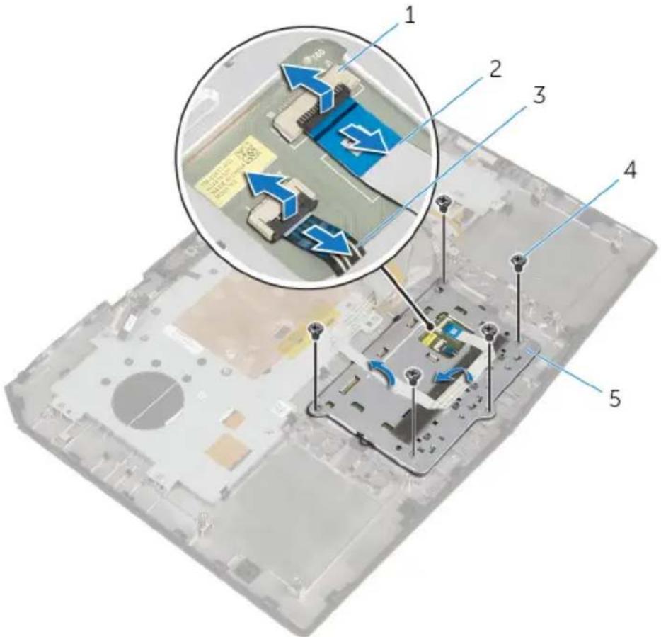
1 latches (2) 2 touch-pad cable
3 touch-pad buttons cable 4 screws (5)
5 touch-pad bracket
4 Release the tabs that secure the touch-pad bracket to the palm-rest assembly and lift the touch-pad bracket off the palm-rest assembly.

1 touch-pad bracket 2 palm-rest assembly 3 tabs (4)
5 Lift the touch pad off the palm-rest assembly.

1 palm-rest assembly 2 touch pad
Replacing the touch pad

WARNING: Before working inside your computer, read the safety information that shipped with your computer and follow the steps in Before working inside your computer. After working inside your computer, follow the instructions in After working inside your computer. For more safety best practices, see the Regulatory Compliance home page at dell.com/regulatory_compliance.
Procedure
1 Using the alignment posts on the palm-rest assembly, place the touch pad on the palm-rest assembly.
2 Align the screw holes on the touch-pad bracket with the screw holes on the palm-rest assembly and snap the touch-pad bracket into place.
3 Replace the screws that secure the touch-pad bracket to the palm-rest assembly.
4 Adhere the touch-pad cable to the touch pad.
5 Slide the touch-pad cable and touch-pad buttons cable into the touch pad and press down on the latches to secure the cables.
Post-requisites
1 Follow the procedure from step 5 to step 11 in "Replacing the palm rest".
2 Replace the solid-state drives.
3 Replace the memory modules.
4 Replace the base panel.
Removing the keyboard

WARNING: Before working inside your computer, read the safety information that shipped with your computer and follow the steps in Before working inside your computer. After working inside your computer, follow the instructions in After working inside your computer. For more safety best practices, see the Regulatory Compliance home page at dell.com/regulatory_compliance.
Prerequisites
1 Remove the base panel.
2 Remove the memory modules.
3 Remove the solid-state drives.
4 Follow the procedure from step 1 to step 11 in "Removing the palm rest".
Procedure
1 Lift the latches and disconnect the touch-pad cable and the status-light cable from the power-button board.
2 Note the touch-pad cable and status-light cable routings and peel off the cables from the keyboard bracket.

1 latches (2) 2 touch-pad cable
3 status-light cable 4 keyboard bracket
3 Remove the screws that secure the keyboard bracket to the palm-rest assembly.

1 keyboard bracket 2 screws (8)
4 Lift the keyboard bracket at an angle and remove it from the tabs on the palm-rest assembly.

1 keyboard bracket 2 palm-rest assembly 3 tabs (3)
5 Remove the screws that secure the keyboard to the palm-rest assembly.

1 keyboard 2 screws (2)
6 Lift the keyboard at an angle and remove it from the tabs on the palm-rest assembly.
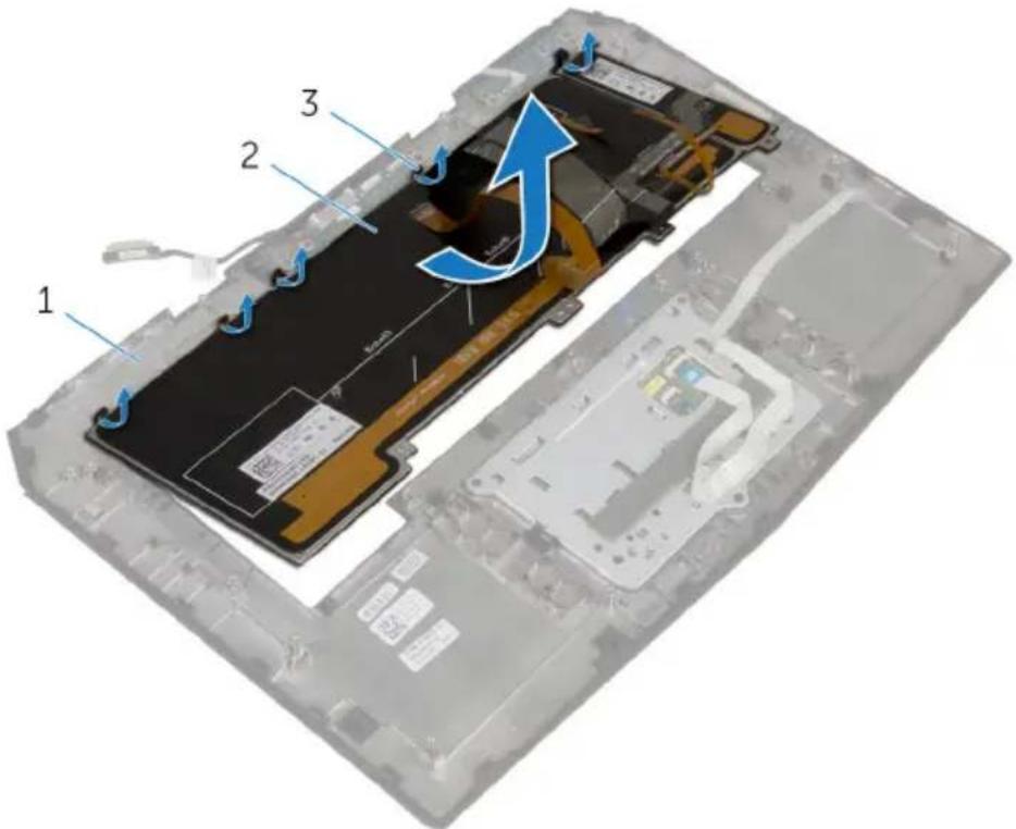
1 palm-rest assembly 2 keyboard
3 tabs (5)
Replacing the keyboard

WARNING: Before working inside your computer, read the safety information that shipped with your computer and follow the steps in Before working inside your computer. After working inside your computer, follow the instructions in After working inside your computer. For more safety best practices, see the Regulatory Compliance home page at dell.com/regulatory_compliance.
Procedure

CAUTION: Make sure that no cables are under the keyboard.
1 Slide the keyboard under the tabs on the palm-rest assembly.
2 Align the screw holes on the keyboard with the screw holes on the palm-rest assembly.
3 Replace the screws that secure the keyboard to the palm-rest assembly.
4 Align the screw holes on the keyboard bracket with the screw holes on the palm-rest assembly and snap the keyboard bracket into place.
5 Replace the screws that secure the keyboard bracket to the palm-rest assembly.
6 Adhere the touch-pad cable and status-light cable to the keyboard bracket.
7 Slide the touch-pad cable and the status-light cable into the power-button board and press down on the latches to secure the cables.
Post-requisites
1 Follow the procedure from step 5 to step 12 in "Replacing the palm rest".
2 Replace the solid-state drives.
3 Replace the memory modules.
4 Replace the base panel.
Removing the power-button board

WARNING: Before working inside your computer, read the safety information that shipped with your computer and follow the steps in Before working inside your computer. After working inside your computer, follow the instructions in After working inside your computer. For more safety best practices, see the Regulatory Compliance home page at dell.com/regulatory_compliance.
Prerequisites
1 Remove the base panel.
2 Remove the memory modules.
3 Remove the solid-state drives.
4 Follow the procedure from step 1 to step 12 in "Removing the palm rest".
Procedure
1 Lift the latches and disconnect the touch-pad cable and status-light cable from the power-button board.
2 Disconnect the power-button board cable from the power-button board.

1 power-button board cable 2 latches (2)
3 touch-pad cable 4 status-light cable
3 Remove the screws that secure the power-button board to the palm-rest assembly.
4 Lift the power-button board off the palm-rest assembly.
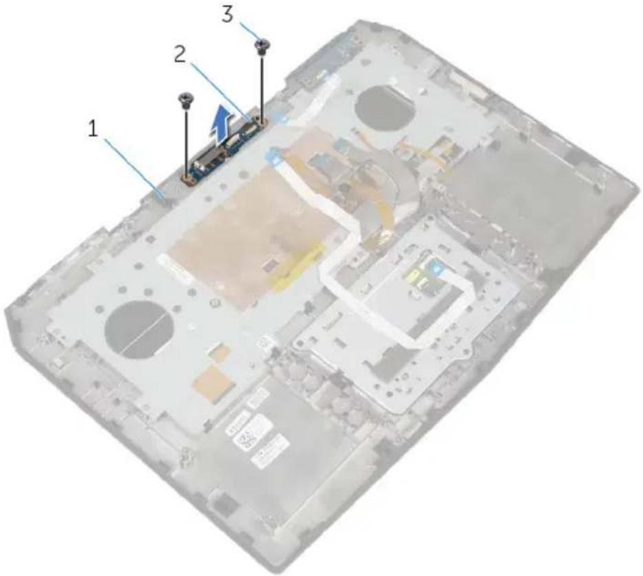
1 palm-rest assembly 2 power-button board 3 screws (2)
Replacing the power-button board

WARNING: Before working inside your computer, read the safety information that shipped with your computer and follow the steps in Before working inside your computer. After working inside your computer, follow the instructions in After working inside your computer. For more safety best practices, see the Regulatory Compliance home page at dell.com/regulatory_compliance.
Procedure
1 Align the screw holes on the power-button board with the screw holes on the palm-rest assembly.
2 Replace the screws that secure the power-button board to the palm-rest assembly.
3 Slide the touch-pad cable and status-light cable into the power-button board and press down on the latches to secure the cables.
4 Connect the power-button board cable to the power-button board.
Post-requisites
1 Follow the procedure from step 5 to step 11 in "Replacing the palm rest".
2 Replace the solid-state drives.
3 Replace the memory modules.
4 Replace the base panel.
Removing the status-light board

WARNING: Before working inside your computer, read the safety information that shipped with your computer and follow the steps in Before working inside your computer. After working inside your computer, follow the instructions in After working inside your computer. For more safety best practices, see the Regulatory Compliance home page at dell.com/regulatory_compliance.
Prerequisites
1 Remove the base panel.
2 Remove the memory modules.
3 Remove the solid-state drives.
4 Follow the procedure from step 1 to step 12 in "Removing the palm rest".
Procedure
1 Lift the latch and disconnect the status-light board cable from the status-light board.

1 latch 2 status-light board cable
3 status-light board
2 Remove the screws that secure the status-light board to the palm-rest assembly.
3 Lift the status-light board off the palm-rest assembly.

1 screws (2) 2 status-light board
3 palm-rest assembly
Replacing the status-light board

WARNING: Before working inside your computer, read the safety information that shipped with your computer and follow the steps in Before working inside your computer. After working inside your computer, follow the instructions in After working inside your computer. For more safety best practices, see the Regulatory Compliance home page at dell.com/regulatory_compliance.
Procedure
1 Align the screw holes on the status-light board with the screw holes on the palm-rest assembly.
2 Replace the screws that secure the status-light board to the palm-rest assembly.
3 Slide the status-light board cable into the status-light board and press down on the latch to secure the cable.
Post-requisites
1 Follow the procedure from step 5 to step 11 in "Replacing the palm rest".
2 Replace the solid-state drives.
3 Replace the memory modules.
4 Replace the base panel.
Removing the I/O board

WARNING: Before working inside your computer, read the safety information that shipped with your computer and follow the steps in Before working inside your computer. After working inside your computer, follow the instructions in After working inside your computer. For more safety best practices, see the Regulatory Compliance home page at dell.com/regulatory_compliance.
Prerequisites
1 Remove the base panel.
2 Remove the memory module.
3 Remove the solid-state drives.
4 Follow the procedure from step 1 to step 11 in "Removing the palm rest".
Procedure
1 Lift the latch and disconnect the I/O-board cable from the I/O board.
2 Remove the screws that secure the I/O-board to the computer base.
3 Lift the I/O board off the computer base.
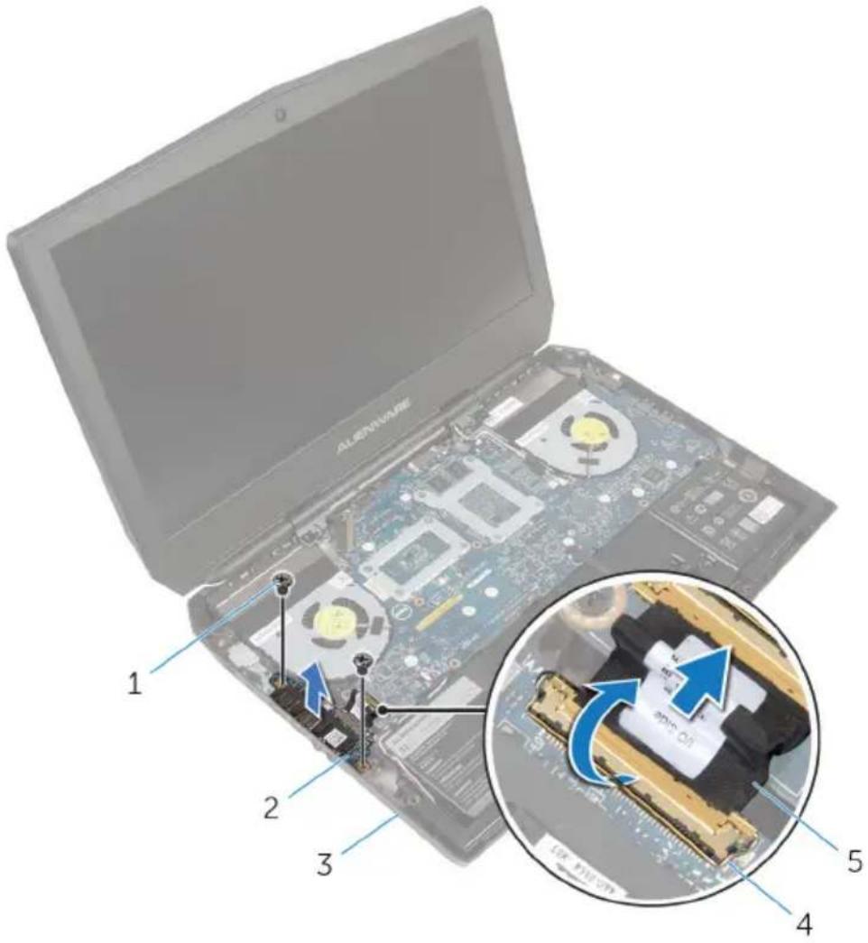
1 screws (2) 2 I/O board
3 computer base 4 latch
5 I/O-board cable
Replacing the I/O board

WARNING: Before working inside your computer, read the safety information that shipped with your computer and follow the steps in Before working inside your computer. After working inside your computer, follow the instructions in After working inside your computer. For more safety best practices, see the Regulatory Compliance home page at dell.com/regulatory_compliance.
Procedure
1 Align the screw holes on the I/O board with the screw holes on the computer base.
2 Replace the screws that secure the I/O board to the computer base.
3 Slide the I/O-board cable into the I/O board and press down on the latch to secure the cable.
Post-requisites
1 Follow the procedure from step 5 to step 11 in "Replacing the palm rest".
2 Replace the solid-state drives.
3 Replace the memory module.
4 Replace the base panel.
Removing the speakers

WARNING: Before working inside your computer, read the safety information that shipped with your computer and follow the steps in Before working inside your computer. After working inside your computer, follow the instructions in After working inside your computer. For more safety best practices, see the Regulatory Compliance home page at dell.com/regulatory_compliance.
Prerequisites
1 Remove the base panel.
2 Remove the memory modules.
3 Remove the solid-state drives.
4 Follow the procedure from step 1 to step 11 in "Removing the palm rest".
Procedure
1 Disconnect the speaker cable from the system board.
2 Peel of the tape and disconnect the front AlienFX LED cable from the system board.
3 Note the front AlienFX LED cable routing and peel off the cable from the battery.

1 speaker cable 2 tape
3 front AlienFX LED cable 4 speakers (2)
4 Remove the speaker cable from the routing guides on the battery and computer base.
5 Lift the speakers along with its cable off the computer base.

1 routing guides (6) 2 speaker cable
3 battery 4 computer base
5 speakers (2)
Replacing the speakers

WARNING: Before working inside your computer, read the safety information that shipped with your computer and follow the steps in Before working inside your computer. After working inside your computer, follow the instructions in After working inside your computer. For more safety best practices, see the Regulatory Compliance home page at dell.com/regulatory_compliance.
Procedure
1 Using the alignment posts, place the speakers on the computer base.
2 Route the speaker cable through the routing guides on the battery and computer base.
3 Adhere the front AlienFX LED cable to the battery.
4 Connect the front AlienFX LED cable to the system board and secure it with the tape.
5 Connect the speaker cable to the system board.
Post-requisites
1 Follow the procedure from step 5 to step 11 in "Replacing the palm rest".
2 Replace the solid-state drives.
3 Replace the memory modules.
4 Replace the base panel.
Removing the front AlienFX LED boards

WARNING: Before working inside your computer, read the safety information that shipped with your computer and follow the steps in Before working inside your computer. After working inside your computer, follow the instructions in After working inside your computer. For more safety best practices, see the Regulatory Compliance home page at dell.com/regulatory_compliance.
Prerequisites
1 Remove the base panel.
2 Remove the memory modules.
3 Remove the solid-state drives.
4 Follow the procedure from step 1 to step 11 in "Removing the palm rest".
Procedure
1 Remove the screws that secure the front AlienFX LED boards to the computer base.
2 Lift the front AlienFX LED boards and disconnect the front AlienFX LED board cables from the front AlienFX LED boards.
3 Remove the screws that secure the front AlienFX LED boards to the tubes.
4 Lift the front AlienFX LED boards of the tubes.

1 front AlienFX LED board cables (2)
2 screws (4)
3 front AlienFX LED boards (2) 4 tubes (2)
5 computer base
Replacing the front AlienFX LED board

WARNING: Before working inside your computer, read the safety information that shipped with your computer and follow the steps in Before working inside your computer. After working inside your computer, follow the instructions in After working inside your computer. For more safety best practices, see the Regulatory Compliance home page at dell.com/regulatory_compliance.
Procedure
1 Align the screw holes on the front AlienFX LED boards with the screw holes on the tubes.
2 Replace the screws that secure the front AlienFX LED boards to the tubes.
3 Connect the front AlienFX LED board cables to the front AlienFX LED boards.
4 Align the screw holes on the front AlienFX LED boards with the screw holes on the computer base.
5 Replace the screws that secure the front AlienFX LED board to the computer base.
Post-requisites
1 Follow the procedure from step 5 to step 11 in "Replacing the palm rest".
2 Replace the solid-state drives.
3 Replace the memory modules.
4 Replace the base panel.
Removing the hinge covers

WARNING: Before working inside your computer, read the safety information that shipped with your computer and follow the steps in Before working inside your computer. After working inside your computer, follow the instructions in After working inside your computer. For more safety best practices, see the Regulatory Compliance home page at dell.com/regulatory_compliance.
Prerequisites
1 Remove the base panel.
2 Remove the memory modules.
3 Remove the solid-state drives.
4 Follow the procedure from step 1 to step 11 in "Removing the palm rest".
Procedure
1 Remove the screws that secure the hinge covers to the computer base.
2 Open the display as far as possible.
3 Remove the hinge covers from the computer base.

1 display assembly 2 screws (2)
3 hinge covers (2) 4 computer base
Replacing the hinge covers

WARNING: Before working inside your computer, read the safety information that shipped with your computer and follow the steps in Before working inside your computer. After working inside your computer, follow the instructions in After working inside your computer. For more safety best practices, see the Regulatory Compliance home page at dell.com/regulatory_compliance.
Procedure
1 Align the screw holes on the hinge covers with the screw holes on the computer base and snap the hinge covers into place.
2 Replace the screws that secure the hinge covers to the computer base.
Post-requisites
1 Follow the procedure from step 5 to step 11 in "Replacing the palm rest".
2 Replace the solid-state drives.
3 Replace the memory modules.
4 Replace the base panel.
Removing the display assembly

WARNING: Before working inside your computer, read the safety information that shipped with your computer and follow the steps in Before working inside your computer. After working inside your computer, follow the instructions in After working inside your computer. For more safety best practices, see the Regulatory Compliance home page at dell.com/regulatory_compliance.
Prerequisites
1 Remove the base panel.
2 Remove the memory modules.
3 Remove the solid-state drives.
4 Remove the wireless card.
5 Follow the procedure from step 1 to step 11 in "Removing the palm rest".
6 Remove the hinge covers.
Procedure
1 Close the display and turn the computer over.
2 Remove the antenna cables from the routing guide on the computer base.
3 Remove the screws that secure the display assembly to the computer base.

natural_image
Laptop case with internal components and labeled parts (no text or symbols beyond labels)1 display assembly 2 computer base
3 screws (2)
4 Turn the computer over and open the display as far as possible.
5 Carefully remove the antenna cables through the slot on the computer base.
6 Peel off the adhesive tape that secures the antenna cables to the system board.
7 Remove the antenna cables from the routing guide on the display hinges.
8 Lift the latch and disconnect the display cable from the system board.
9 Peel off the adhesive tape, disconnect the logo-board cable from the system board, and remove it from the routing guide on the display hinges.
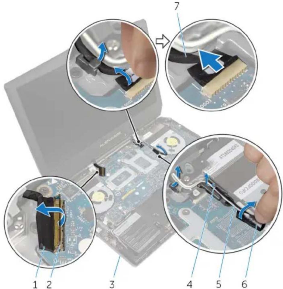
1 display cable 2 latch
3 computer base 4 routing guides (2)
5 antenna cables (2) 6 adhesive tapes (2)
7 logo-board cable
10 Remove the screws that secure the display assembly to the computer base.
11 Lift the display assembly off the computer base.
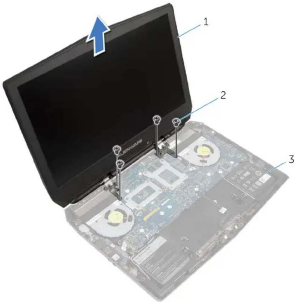
1 display assembly 2 screws (4)
3 computer base
Replacing the display assembly

WARNING: Before working inside your computer, read the safety information that shipped with your computer and follow the steps in Before working inside your computer. After working inside your computer, follow the instructions in After working inside your computer. For more safety best practices, see the Regulatory Compliance home page at dell.com/regulatory_compliance.
Procedure
1 Align the screw holes on the display hinges with the screw holes on the computer base.
2 Replace the screws that secure the display hinges to the computer base.
3 Route the logo-board cable through the routing guide on the display hinge.
4 Connect the logo-board cable to the system board and secure it with the tape.
5 Slide the display cable into the system board and press down on the latch to secure the cable.
6 Route the antenna cables through the routing guide on the display hinges.
7 Adhere the adhesive tape that secure the antenna cables to the system board.
8 Slide the antenna cables through the slot on the computer base.
9 Close the display and turn the computer over.
10 Route the antenna cables through the routing guide on the computer base.
11 Replace the screws that secure the display assembly to the computer base.
12 Turn the computer over and open the display as far as possible.
Post-requisites
1 Replace the hinge covers.
2 Follow the procedure from step 5 to step 11 in "Replacing the palm rest".
3 Replace the wireless card.
4 Replace the solid-state drives.
5 Replace the memory modules.
6 Replace the base panel.
Removing the display bezel

WARNING: Before working inside your computer, read the safety information that shipped with your computer and follow the steps in Before working inside your computer. After working inside your computer, follow the instructions in After working inside your computer. For more safety best practices, see the Regulatory Compliance home page at dell.com/regulatory_compliance.
Prerequisites
1 Remove the base panel.
2 Remove the memory modules.
3 Remove the solid-state drives.
4 Remove the wireless card.
5 Follow the procedure from step 1 to step 11 in "Removing the palm rest".
6 Remove the hinge covers.
7 Remove the display assembly.
Procedure
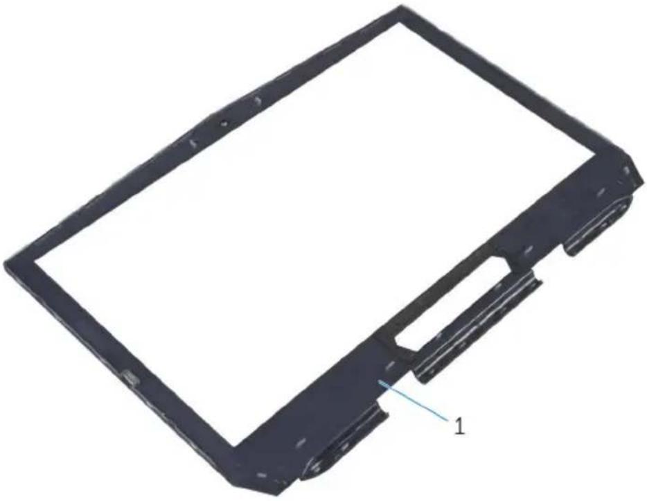
1 Using your fingertips, carefully pry up the inside edges of the display bezel.
2 Carefully lift the display bezel and turn it over.

1 display bezel
3 Lift the latches and disconnect the display-board cables from the logo board.
4 Peel off the adhesive tape and disconnect the logo-board cable from the logo board.

1 logo board 2 display-board cables (3)
3 adhesive tape 4 logo-board cable
5 Follow the procedure from step 1 to step 2 in "Removing the logo board".
natural_image
3D rendering of a black rectangular electronic component with a labeled feature '1' (no text or symbols beyond the label)1 display bezel
Replacing the display bezel

WARNING: Before working inside your computer, read the safety information that shipped with your computer and follow the steps in Before working inside your computer. After working inside your computer, follow the instructions in After working inside your computer. For more safety best practices, see the Regulatory Compliance home page at dell.com/regulatory_compliance.
Procedure
1 Follow the procedure from step 1 to step 2 in "Replacing the logo board".
2 Connect the logo-board cable to the logo board and secure it with the adhesive tape.
3 Slide the display-board cables into the logo board and press down on the latches to secure the cables.
4 Carefully turn the display bezel over.
5 Align the display bezel with the display back-cover and gently snap the display bezel into place.
Post-requisites
1 Replace the display assembly.
2 Replace the hinge covers.
3 Follow the procedure from step 5 to step 11 in "Replacing the palm rest".
4 Replace the wireless card.
5 Replace the solid-state drives.
6 Replace the memory modules.
7 Replace the base panel.
Removing the display panel

WARNING: Before working inside your computer, read the safety information that shipped with your computer and follow the steps in Before working inside your computer. After working inside your computer, follow the instructions in After working inside your computer. For more safety best practices, see the Regulatory Compliance home page at dell.com/regulatory_compliance.
Prerequisites
1 Remove the base panel.
2 Remove the memory modules.
3 Remove the solid-state drives.
4 Remove the wireless card.
5 Follow the procedure from step 1 to step 11 in "Removing the palm rest".
6 Remove the hinge covers.
7 Remove the display assembly.
8 Follow the procedure from step 1 to step 4 in "Removing the display bezel".
Procedure
1 Remove the screws that secure the display panel to the display back-cover.
2 Gently lift the display panel and turn it over.
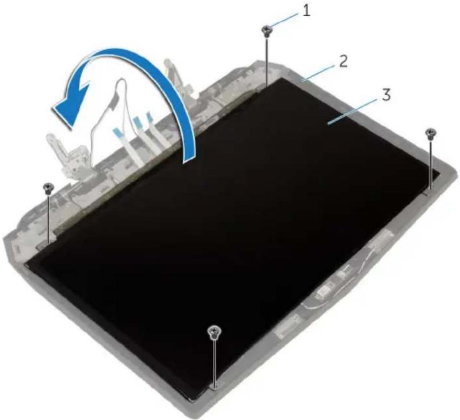
1 screws (4) 2 display back-cover
3 display panel
3 Lift the latch and disconnect the display cable from the display panel.
4 Lift the display panel off the display back-cover.

1 display panel 2 latch
3 display cable 4 display back-cover
Replacing the display panel

WARNING: Before working inside your computer, read the safety information that shipped with your computer and follow the steps in Before working inside your computer. After working inside your computer, follow the instructions in After working inside your computer. For more safety best practices, see the Regulatory Compliance home page at dell.com/regulatory_compliance.
Procedure
1 Slide the display cable into the display panel and press down on the latch to secure the cable.
2 Turn the display panel over.
3 Align the screw holes on the display panel with the screw holes on the display back-cover.
4 Replace the screws that secure the display panel to the display back-cover.
Post-requisites
1 Follow the procedure from step 2 to step 5 in "Replacing the display bezel".
2 Replace the display assembly.
3 Replace the hinge covers.
4 Follow the procedure from step 5 to step 11 in "Replacing the palm rest".
5 Replace the wireless card.
6 Replace the solid-state drives.
7 Replace the memory modules.
8 Replace the base panel.
Removing the display hinges

WARNING: Before working inside your computer, read the safety information that shipped with your computer and follow the steps in Before working inside your computer. After working inside your computer, follow the instructions in After working inside your computer. For more safety best practices, see the Regulatory Compliance home page at dell.com/regulatory_compliance.
Prerequisites
1 Remove the base panel.
2 Remove the memory modules.
3 Remove the solid-state drives.
4 Remove the wireless card.
5 Follow the procedure from step 1 to step 11 in "Removing the palm rest".
6 Remove the hinge covers.
7 Remove the display assembly.
8 Follow the procedure from step 1 to step 4 in "Removing the display bezel".
Procedure
1 Remove the screws that secure the display hinges to the display back-cover.
2 Lift the display hinges off the display assembly.

1 display hinges (2) 2 screws (6)
3 display back-cover
Replacing the display hinges

WARNING: Before working inside your computer, read the safety information that shipped with your computer and follow the steps in Before working inside your computer. After working inside your computer, follow the instructions in After working inside your computer. For more safety best practices, see the Regulatory Compliance home page at dell.com/regulatory_compliance.
Procedure
1 Align the screw holes on the display hinges with the screw holes on the display back-cover.
2 Replace the screws that secure the display hinges to the display back-cover.
Post-requisites
1 Follow the procedure from step 2 to step 5 in "Replacing the display bezel".
2 Replace the display assembly.
3 Replace the hinge covers.
4 Follow the procedure from step 5 to step 11 in "Replacing the palm rest".
5 Replace the wireless card.
6 Replace the solid-state drives.
7 Replace the memory modules.
8 Replace the base panel.
Removing the display back-cover

WARNING: Before working inside your computer, read the safety information that shipped with your computer and follow the steps in Before working inside your computer. After working inside your computer, follow the instructions in After working inside your computer. For more safety best practices, see the Regulatory Compliance home page at dell.com/regulatory_compliance.
Prerequisites
1 Remove the base panel.
2 Remove the memory modules.
3 Remove the solid-state drives.
4 Remove the wireless card.
5 Follow the procedure from step 1 to step 11 in "Removing the palm rest".
6 Remove the hinge covers.
7 Remove the display assembly.
8 Follow the procedure from step 1 to step 4 in "Removing the display bezel".
9 Remove the display panel.
10 Remove the display hinges.
11 Remove the camera.
Procedure
1 Note the display-board cable routing and remove the cable from the routing guides on the display back-cover.
2 Peel off the display board and camera cable from the display back-cover.

1 display back-cover 2 display board and camera cable
3 routing guides (3)
3 Follow the procedure from step 1 to step 4 in "Removing the Alienware AlienHead LED board".
4 Follow the procedure from step 1 to step 4 in "Removing the display-panel AlienFX LEDs".
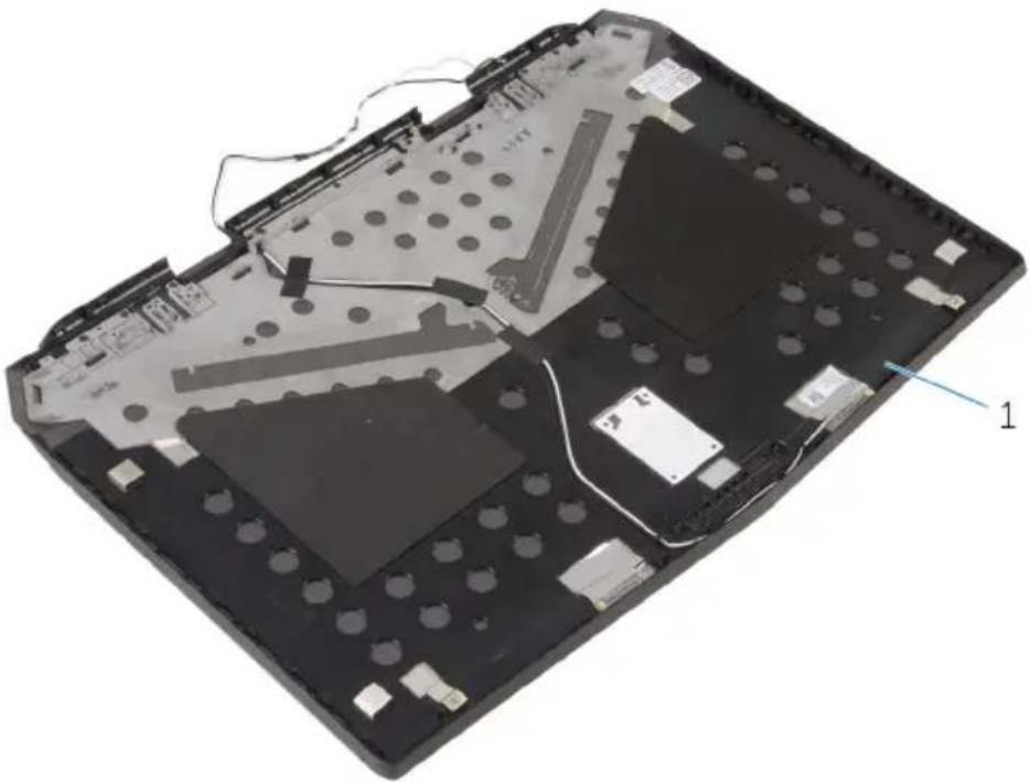
natural_image
Laptop's back panel with visible internal components and mounting holes (no text or symbols)1 display back-cover
Replacing the display back-cover

WARNING: Before working inside your computer, read the safety information that shipped with your computer and follow the steps in Before working inside your computer. After working inside your computer, follow the instructions in After working inside your computer. For more safety best practices, see the Regulatory Compliance home page at dell.com/regulatory_compliance.
Procedure
1 Place the display back-cover on a clean and flat surface.
2 Follow the procedure from step 1 to step 3 in "Replacing the Alienware AlienHead LED board".
3 Follow the procedure from step 1 to step 3 in "Replacing the display-panel AlienFX LEDs".
4 Adhere the display board and camera cable to the display back-cover.
5 Route the display-board cable through the routing guides on the display back-cover.
Post-requisites
1 Replace the camera.
2 Replace the display hinges.
3 Replace the display panel.
4 Follow the procedure from step 2 to step 5 in "Replacing the display bezel".
5 Replace the display assembly.
6 Replace the hinge covers.
7 Follow the procedure from step 5 to step 11 in "Replacing the palm rest".
8 Replace the wireless card.
9 Replace the solid-state drives.
10 Replace the memory modules.
11 Replace the base panel.
Removing the camera

WARNING: Before working inside your computer, read the safety information that shipped with your computer and follow the steps in Before working inside your computer. After working inside your computer, follow the instructions in After working inside your computer. For more safety best practices, see the Regulatory Compliance home page at dell.com/regulatory_compliance.
Prerequisites
1 Remove the base panel.
2 Remove the memory modules.
3 Remove the solid-state drives.
4 Remove the wireless card.
5 Follow the procedure from step 1 to step 11 in "Removing the palm rest".
6 Remove the hinge covers.
7 Remove the display assembly.
8 Follow the procedure from step 1 to step 4 in "Removing the display bezel".
9 Remove the display panel.
Procedure
1 Peel off the tape that secures the camera cable to the camera and disconnect the camera cable from the camera module.
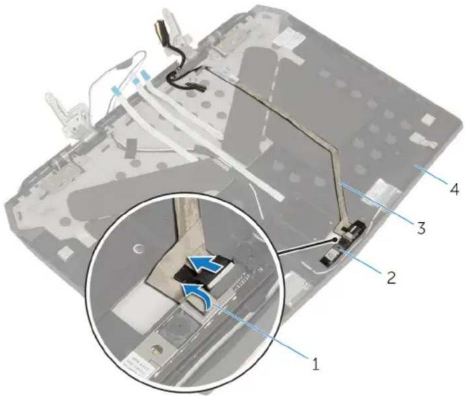
1 tape 2 camera module
3 camera cable 4 display back-cover
2 Note the location of the camera module and pry it off the display back-cover using a plastic scribe.
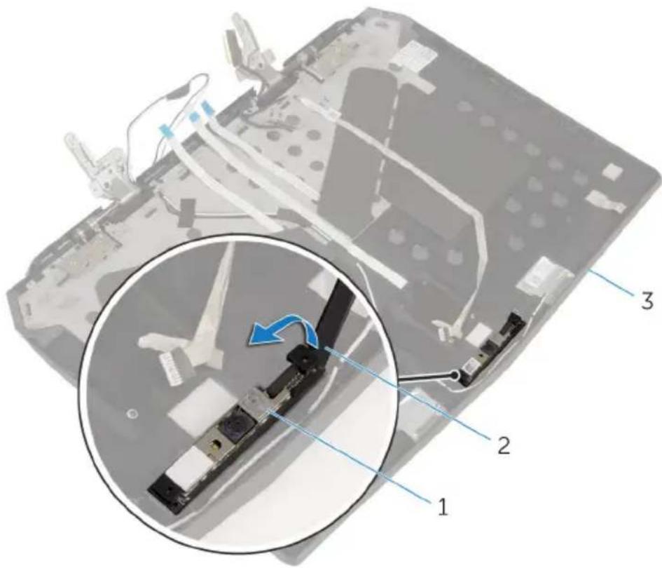
1 camera module 2 plastic scribe
3 display back-cover
Replacing the camera

WARNING: Before working inside your computer, read the safety information that shipped with your computer and follow the steps in Before working inside your computer. After working inside your computer, follow the instructions in After working inside your computer. For more safety best practices, see the Regulatory Compliance home page at dell.com/regulatory_compliance.
Procedure
1 Using the alignment posts, adhere the camera module to the display back-cover.
2 Connect the camera cable to the camera module and adhere the tape that secures the camera cable to the camera module.
Post-requisites
1 Replace the display panel.
2 Follow the procedure from step 2 to step 5 in "Replacing the display bezel".
3 Replace the display assembly.
4 Replace the hinge covers.
5 Follow the procedure from step 5 to step 11 in "Replacing the palm rest".
6 Replace the wireless card.
7 Replace the solid-state drives.
8 Replace the memory modules.
9 Replace the base panel.
Removing the Alienware AlienHead LED board

WARNING: Before working inside your computer, read the safety information that shipped with your computer and follow the steps in Before working inside your computer. After working inside your computer, follow the instructions in After working inside your computer. For more safety best practices, see the Regulatory Compliance home page at dell.com/regulatory_compliance.
Prerequisites
1 Remove the base panel.
2 Remove the memory modules.
3 Remove the solid-state drives.
4 Remove the wireless card.
5 Follow the procedure from step 1 to step 11 in "Removing the palm rest".
6 Remove the hinge covers.
7 Remove the display assembly.
8 Follow the procedure from step 1 to step 4 in "Removing the display bezel".
9 Remove the display panel.
10 Follow the procedure from step 1 to step 2 in "Removing the display back-cover".
Procedure
1 Peel off the tape that secures the Alienware AlienHead LED board to the display back-cover.
2 Note the Alienware AlienHead LED cable routing and peel off the cable from the display back-cover.
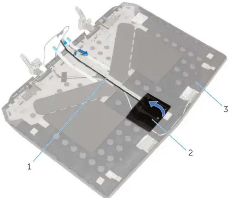
1 Alienware AlienHead LED cable
2 tape
3 display back-cover
3 Note the location of the Alienware AlienHead LED board and peel off the Alienware AlienHead LED board from the display back-cover.
4 Lift Alienware AlienHead LED board along with its cable off the display back-cover.

1 Alienware AlienHead LED cable
2 Alienware AlienHead LED board
3 display back-cover
Replacing the Alienware AlienHead LED board

WARNING: Before working inside your computer, read the safety information that shipped with your computer and follow the steps in Before working inside your computer. After working inside your computer, follow the instructions in After working inside your computer. For more safety best practices, see the Regulatory Compliance home page at dell.com/regulatory_compliance.
Procedure
1 Adhere the Alienware AlienHead LED board to the display back-cover.
2 Route the Alienware AlienHead LED cable on the display back-cover and adhere it to the display back-cover.
3 Adhere the tape that secures the Alienware AlienHead LED board to the display back-cover.
Post-requisites
1 Follow the procedure from step 4 to step 5 in "Replacing the display back-cover".
2 Replace the display panel.
3 Follow the procedure from step 2 to step 5 in "Replacing the display bezel".
4 Replace the display assembly.
5 Replace the hinge covers.
6 Follow the procedure from step 5 to step 11 in "Replacing the palm rest".
7 Replace the wireless card.
8 Replace the solid-state drives.
9 Replace the memory modules.
10 Replace the base panel.
Removing the display-panel AlienFX LEDs

WARNING: Before working inside your computer, read the safety information that shipped with your computer and follow the steps in Before working inside your computer. After working inside your computer, follow the instructions in After working inside your computer. For more safety best practices, see the Regulatory Compliance home page at dell.com/regulatory_compliance.
Prerequisites
1 Remove the base panel.
2 Remove the memory modules.
3 Remove the solid-state drives.
4 Remove the wireless card.
5 Follow the procedure from step 1 to step 11 in "Removing the palm rest".
6 Remove the hinge covers.
7 Remove the display assembly.
8 Follow the procedure from step 1 to step 4 in "Removing the display bezel".
9 Remove the display panel.
10 Follow the procedure from step 1 to step 2 in "Removing the display back-cover".
Procedure
1 Peel off the tapes that secure the display-panel AlienFX LEDs to the display back-cover.
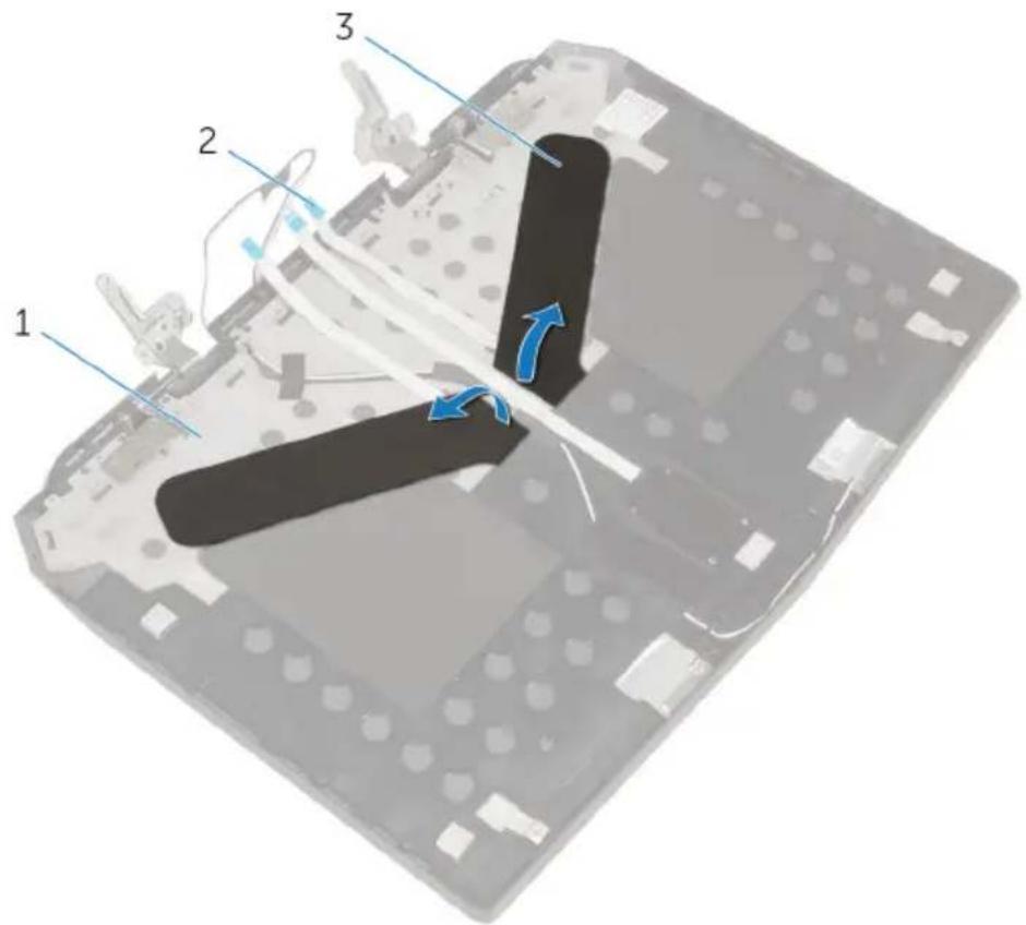
1 display back-cover 2 display-panel AlienFX LED cables (2)
3 tapes (2)
2 Note the routing of the display-panel AlienFX LED cables and peel off the cables from the display back-cover.
3 Note the location of the display-panel AlienFX LEDs and peel off the LEDs from the display back-cover.
4 Lift the display-panel AlienFX LEDs along with the cables off the display back-cover.

1 display back-cover 2 display-panel AlienFX LED cables (2)
3 display-panel AlienFX LEDs (2)
Replacing the display-panel AlienFX LEDs

WARNING: Before working inside your computer, read the safety information that shipped with your computer and follow the steps in Before working inside your computer. After working inside your computer, follow the instructions in After working inside your computer. For more safety best practices, see the Regulatory Compliance home page at dell.com/regulatory_compliance.
Procedure
1 Adhere the display-panel AlienFX LEDs to the display back-cover.
2 Route the display-panel AlienFX LED cables on the display back-cover and adhere the cables to the display back-cover.
3 Adhere the tapes that secure the display-panel AlienFX LEDs to the display back-cover.
Post-requisites
1 Follow the procedure from step 4 to step 5 in "Replacing the display back-cover".
2 Replace the display panel.
3 Follow the procedure from step 2 to step 5 in "Replacing the display bezel".
4 Replace the display assembly.
5 Replace the hinge covers.
6 Follow the procedure from step 5 to step 11 in "Replacing the palm rest".
7 Replace the wireless card.
8 Replace the solid-state drives.
9 Replace the memory modules.
10 Replace the base panel.
Removing the logo board

WARNING: Before working inside your computer, read the safety information that shipped with your computer and follow the steps in Before working inside your computer. After working inside your computer, follow the instructions in After working inside your computer. For more safety best practices, see the Regulatory Compliance home page at dell.com/regulatory_compliance.
Prerequisites
1 Remove the base panel.
2 Remove the memory modules.
3 Remove the solid-state drives.
4 Remove the wireless card.
5 Follow the procedure from step 1 to step 11 in "Removing the palm rest".
6 Remove the hinge covers.
7 Remove the display assembly.
8 Follow the procedure from step 1 to step 4 in "Removing the display bezel".
Procedure
1 Turn the display bezel over and place it on a clean and flat surface.
2 Note the location of the logo board and pry the logo board off the display bezel using a plastic scribe.

1 display bezel 2 logo board
3 plastic scribe
Replacing the logo board

WARNING: Before working inside your computer, read the safety information that shipped with your computer and follow the steps in Before working inside your computer. After working inside your computer, follow the instructions in After working inside your computer. For more safety best practices, see the Regulatory Compliance home page at dell.com/regulatory_compliance.
Procedure
1 Adhere the logo board to the display bezel.
2 Turn the display bezel over.
Post-requisites
1 Follow the procedure from step 2 to step 5 in "Replacing the display bezel".
2 Replace the display assembly.
3 Replace the hinge covers.
4 Follow the procedure from step 5 to step 11 in "Replacing the palm rest".
5 Replace the wireless card.
6 Replace the solid-state drives.
7 Replace the memory modules.
8 Replace the base panel.
Removing the system board

WARNING: Before working inside your computer, read the safety information that shipped with your computer and follow the steps in Before working inside your computer. After working inside your computer, follow the instructions in After working inside your computer. For more safety best practices, see the Regulatory Compliance home page at dell.com/regulatory_compliance.

NOTE: Your computer's Service Tag is stored in the system board. You must enter the Service Tag in the BIOS setup program after you replace the system board.

NOTE: Replacing the system board removes any changes you have made to the BIOS using the BIOS setup program. You must make the desired changes again after you replace the system board.

NOTE: Before disconnecting the cables from the system board, note the location of the connectors so that you can reconnect them correctly after you replace the system board.
Prerequisites
1 Remove the base panel.
2 Remove the memory modules.
3 Remove the solid-state drives.
4 Remove the wireless card.
5 Follow the procedure from step 1 to step 11 in "Removing the palm rest".
6 Remove the hinge covers.
7 Remove the display assembly.
Procedure
1 Turn the computer over.
2 Disconnect the fan cables and power-adapter port cable from the system board.
3 Using the pull tab, disconnect the hard-drive cable from the system board.

1 pull tab 2 hard-drive cable
3 power-adapter port cable 4 computer base
5 fan cables (2)
4 Turn the computer over.
5 Lift the latch and disconnect the I/O-board cable from the system board.
6 Disconnect the speaker cable from the system board.
7 Peel the tape and disconnect the front AlienFX LED cable from the system board.
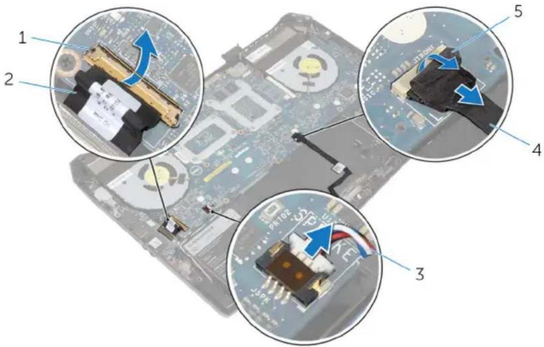
1 latch 2 I/O-board cable
3 speaker cable 4 front AlienFX LED cable
5 tape
8 Remove the screws that secure the system board to the computer base.
9 Lift the system board at an angle and slide the ports on the system board out of the slots on the computer base.
10 Lift the system board off the computer base.
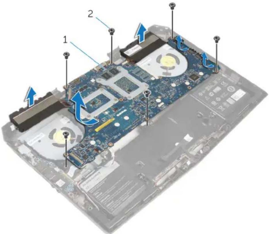
1 system board 2 screws (6)
11 Turn the system board over.
12 Follow the procedure from step 1 to step 2 in "Removing the heat-sink assembly".
13 Follow the procedure from step 1 to step 2 in "Removing the coin-cell battery".
Replacing the system board

WARNING: Before working inside your computer, read the safety information that shipped with your computer and follow the steps in Before working inside your computer. After working inside your computer, follow the instructions in After working inside your computer. For more safety best practices, see the Regulatory Compliance home page at dell.com/regulatory_compliance.

NOTE: Your computer's Service Tag is stored in the system board. You must enter the Service Tag in the BIOS setup program after you replace the system board.

NOTE: Replacing the system board removes any changes you have made to the BIOS using the BIOS setup program. You must make the desired changes again after you replace the system board.
Procedure
1 Follow the procedure from step 1 to step 2 in "Replacing the coin-cell battery".
2 Follow the procedure from step 1 to step 2 in "Replacing the heat-sink assembly".
3 Turn the system board over.
4 Slide the ports on the system board into the slots on the computer base and align the screw holes on the system board with the screw holes on the computer base.

CAUTION: Make sure that no cables are under the system board.
5 Replace the screws that secure the system board to the computer base.
6 Slide the I/O-board cable into the system board and press down on the latch to secure the cable.
7 Connect the speaker cable to the system board.
8 Connect the front AlienFX LED cable to the system board and secure it with the tape.
9 Turn the computer over.
10 Connect the fan cables, power-adapter port cable, and hard-drive cable to the system board.
11 Turn the computer over.
Post-requisites
1 Replace the display assembly.
2 Replace the hinge covers.
3 Follow the procedure from step 5 to step 11 in "Replacing the palm rest".
4 Replace the wireless card.
5 Replace the solid-state drives.
6 Replace the memory modules.
7 Replace the base panel.
Removing the heat-sink assembly

WARNING: Before working inside your computer, read the safety information that shipped with your computer and follow the steps in Before working inside your computer. After working inside your computer, follow the instructions in After working inside your computer. For more safety best practices, see the Regulatory Compliance home page at dell.com/regulatory_compliance.

WARNING: The heat sink may become hot during normal operation. Allow sufficient time for the heat sink to cool before you touch it.

CAUTION: For maximum cooling of the processor, do not touch the heat transfer areas on the heat sink. The oils in your skin can reduce the heat transfer capability of the thermal grease.
Prerequisites
1 Remove the base panel.
2 Remove the memory modules.
3 Remove the solid-state drives.
4 Remove the wireless card.
5 Follow the procedure from step 1 to step 11 in "Removing the palm rest".
6 Remove the hinge covers.
7 Remove the display assembly.
8 Follow the procedure from step 1 to step 11 in "Removing the system board".
Procedure
1 In sequential order (as indicated on the heat-sink assembly), loosen the captive screws that secure the heat-sink assembly to the system board.
2 Lift the heat-sink assembly off the system board.

1 heat-sink assembly 2 system board 3 captive screws (8)
Replacing the heat-sink assembly

WARNING: Before working inside your computer, read the safety information that shipped with your computer and follow the steps in Before working inside your computer. After working inside your computer, follow the instructions in After working inside your computer. For more safety best practices, see the Regulatory Compliance home page at dell.com/regulatory_compliance.

CAUTION: Incorrect alignment of the heat sink can cause damage to the system board and processor.
Procedure
1 Align the screw holes on the heat-sink assembly with the screw holes on the system board.
2 In sequential order (indicated on the heat-sink assembly), tighten the captive screws that secure the heat-sink assembly to the system board.
Post-requisites
1 Follow the procedure from step 3 to step 11 in "Replacing the system board".
2 Replace the display assembly.
3 Replace the hinge covers.
4 Follow the procedure from step 5 to step 11 in "Replacing the palm rest".
5 Replace the wireless card.
6 Replace the solid-state drives.
7 Replace the memory modules.
8 Replace the base panel.
Removing the fans

WARNING: Before working inside your computer, read the safety information that shipped with your computer and follow the steps in Before working inside your computer. After working inside your computer, follow the instructions in After working inside your computer. For more safety best practices, see the Regulatory Compliance home page at dell.com/regulatory_compliance.
Prerequisites
1 Remove the base panel.
2 Remove the memory module.
3 Remove the solid-state drives.
4 Remove the wireless card.
5 Follow the procedure from step 1 to step 11 in "Removing the palm rest".
6 Remove the hinge covers.
7 Remove the display assembly.
8 Follow the procedure from step 1 to step 10 in "Removing the system board".
Procedure
1 Remove the screws that secure the processor fan and video-card fan to the computer base.
2 Lift the processor fan and video-card fan off the computer base.

1 processor fan 2 computer base
3 video-card fan 4 screws (4)
Replacing the fans

WARNING: Before working inside your computer, read the safety information that shipped with your computer and follow the steps in Before working inside your computer. After working inside your computer, follow the instructions in After working inside your computer. For more safety best practices, see the Regulatory Compliance home page at dell.com/regulatory_compliance.
Procedure
1 Align the screw holes on the processor fan and video-card fan with the screw holes on the computer base.
2 Replace screws that secure the processor fan and video-card fan to the computer base.
Post-requisites
1 Follow the procedure from step 4 to step 11 in "Replacing the system board".
2 Replace the display assembly.
3 Replace the hinge covers.
4 Follow the procedure from step 5 to step 11 in "Replacing the palm rest".
5 Replace the wireless card.
6 Replace the solid-state drives.
7 Replace the memory module.
8 Replace the base panel.
Removing the power- adapter port

WARNING: Before working inside your computer, read the safety information that shipped with your computer and follow the steps in Before working inside your computer. After working inside your computer, follow the instructions in After working inside your computer. For more safety best practices, see the Regulatory Compliance home page at dell.com/regulatory_compliance.
Prerequisites
1 Remove the base panel.
2 Remove the memory modules.
3 Remove the solid-state drives.
4 Remove the wireless card.
5 Follow the procedure from step 1 to step 11 in "Removing the palm rest".
6 Remove the hinge covers.
7 Remove the I/O board.
8 Remove the display assembly.
9 Follow the procedure from step 1 to step 10 in "Removing the system board".
Procedure
1 Remove the screws that secure the power-adapter port bracket to the computer base.
2 Lift the power-adapter port bracket off the power-adapter port.
3 Note the power-adapter port cable routing and remove the cable from the routing guides on the computer base.
4 Lift the power-adapter port along with its cable off the computer base.
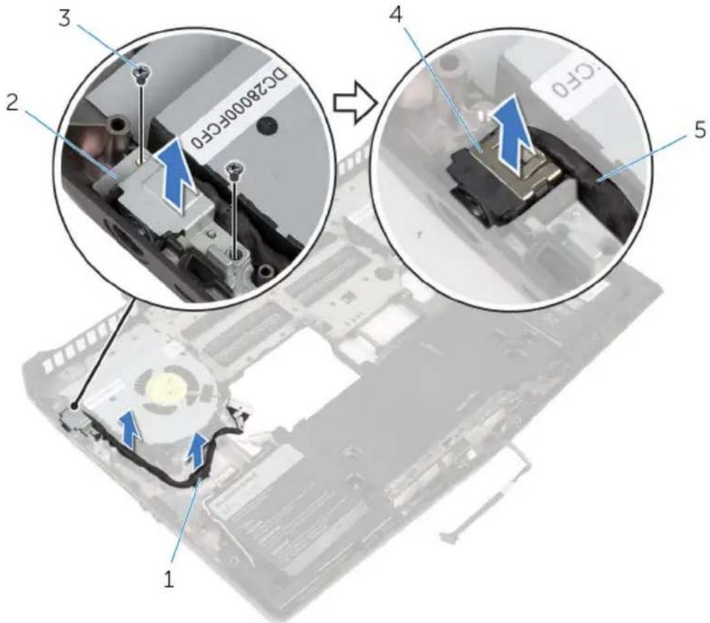
1 routing guide 2 power-adapter port
bracket
3 screws (2) 4 power-adapter port
5 power-adapter port cable
Replacing the power-adapter port

WARNING: Before working inside your computer, read the safety information that shipped with your computer and follow the steps in Before working inside your computer. After working inside your computer, follow the instructions in After working inside your computer. For more safety best practices, see the Regulatory Compliance home page at dell.com/regulatory_compliance.
Procedure
1 Slide the power-adapter port into the slot on the computer base.
2 Align the screw holes on the power-adapter port bracket with the screw holes on the power-adapter port.
3 Replace the screws that secure the power-adapter port bracket to the computer base.
4 Route the power-adapter port cable through the routing guides on the computer base.
Post-requisites
1 Follow the procedure from step 4 to step 11 in "Replacing the system board".
2 Replace the display assembly.
3 Replace the I/O board.
4 Replace the hinge covers.
5 Follow the procedure from step 5 to step 11 in "Replacing the palm rest".
6 Replace the wireless card.
7 Replace the solid-state drives.
8 Replace the memory modules.
9 Replace the base panel.
Removing the coin-cell battery

WARNING: Before working inside your computer, read the safety information that shipped with your computer and follow the steps in Before working inside your computer. After working inside your computer, follow the instructions in After working inside your computer. For more safety best practices, see the Regulatory Compliance home page at dell.com/regulatory_compliance.

CAUTION: Removing the coin-cell battery resets the BIOS settings to default. It is recommended that you note the BIOS settings before removing the coin-cell battery.
Prerequisites
1 Remove the base panel.
2 Remove the memory modules.
3 Remove the solid-state drives.
4 Remove the wireless card.
5 Follow the procedure from step 1 to step 11 in "Removing the palm rest".
6 Remove the hinge covers.
7 Remove the display assembly.
8 Follow the procedure from step 1 to step 11 in "Removing the system board".
Procedure
1 Disconnect the coin-cell battery cable from the system board.
2 Using a plastic scribe, gently pry out the coin-cell battery from the system board.

1 system board 2 coin-cell battery
3 coin-cell battery cable
Replacing the coin-cell battery

WARNING: Before working inside your computer, read the safety information that shipped with your computer and follow the steps in Before working inside your computer. After working inside your computer, follow the instructions in After working inside your computer. For more safety best practices, see the Regulatory Compliance home page at dell.com/regulatory_compliance.
Procedure
1 Adhere the coin-cell battery to the system board.
2 Connect the coin-cell battery cable to the system board.
Post-requisites
1 Follow the procedure from step 3 to step 11 in "Replacing the system board".
2 Replace the display assembly.
3 Replace the hinge covers.
4 Follow the procedure from step 5 to step 11 in "Replacing the palm rest".
5 Replace the wireless card.
6 Replace the solid-state drives.
7 Replace the memory modules.
8 Replace the base panel.
Removing the battery

WARNING: Before working inside your computer, read the safety information that shipped with your computer and follow the steps in Before working inside your computer. After working inside your computer, follow the instructions in After working inside your computer. For more safety best practices, see the Regulatory Compliance home page at dell.com/regulatory_compliance.
Prerequisites
1 Remove the base panel.
2 Remove the memory modules.
3 Remove the solid-state drives.
4 Remove the wireless card.
5 Follow the procedure from step 1 to step 11 in "Removing the palm rest".
6 Remove the hinge covers.
7 Remove the display assembly.
8 Follow the procedure from step 1 to step 10 in "Removing the system board".
Procedure
1 Remove the speaker cable from the routing guides on the battery.
2 Note the front AlienFX LED cable routing and peel off the cable from the battery.
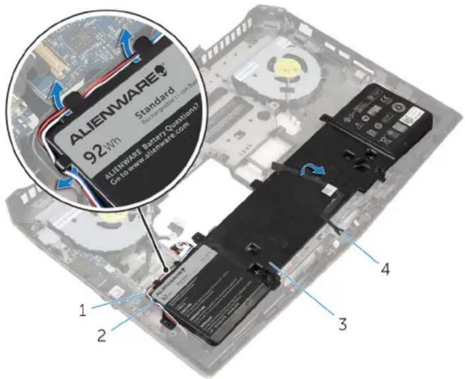
1 speaker cable 2 routing guides (3)
3 battery 4 front AlienFX LED cable
3 Remove the screws that secure the battery to the computer base.
4 Lift the battery off the computer base.

1 screws (2) 2 battery
3 computer base
Replacing the battery

WARNING: Before working inside your computer, read the safety information that shipped with your computer and follow the steps in Before working inside your computer. After working inside your computer, follow the instructions in After working inside your computer. For more safety best practices, see the Regulatory Compliance home page at dell.com/regulatory_compliance.
Procedure
1 Align the screw holes on the battery with the screw holes on the computer base.
2 Replace the screws that secure the battery to the computer base.
3 Adhere the front AlienFX LED cable to the battery.
4 Route the speaker cable through the routing guides on the battery.
Post-requisites
1 Follow the procedure from step 4 to step 11 in "Replacing the system board".
2 Replace the display assembly.
3 Replace the hinge covers.
4 Follow the procedure from step 5 to step 11 in "Replacing the palm rest".
5 Replace the wireless card.
6 Replace the solid-state drives.
7 Replace the memory modules.
8 Replace the base panel.
Removing the computer base

WARNING: Before working inside your computer, read the safety information that shipped with your computer and follow the steps in Before working inside your computer. After working inside your computer, follow the instructions in After working inside your computer. For more safety best practices, see the Regulatory Compliance home page at dell.com/regulatory_compliance.
Prerequisites
1 Remove the base panel.
2 Remove the memory modules.
3 Remove the solid-state drives.
4 Follow the procedure from step 1 to step 5 in "Removing the hard drive".
5 Remove the wireless card.
6 Remove the I/O board.
7 Follow the procedure from step 1 to step 11 in "Removing the palm rest".
8 Remove the hinge covers.
9 Remove the speakers.
10 Remove the front AlienFX LED boards.
11 Remove the display assembly.
12 Follow the procedure from step 1 to step 10 in "Removing the system board".
13 Remove the fans.
14 Remove the battery.
15 Remove the power-adapter port.
Procedure
After performing the prerequisites, we are left with the computer base.
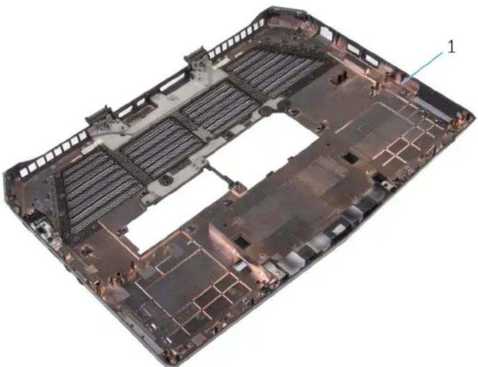
natural_image
Interior view of a car chassis with visible structural ribs and mounting holes (no text or symbols)1 computer base
Replacing the computer base

WARNING: Before working inside your computer, read the safety information that shipped with your computer and follow the steps in Before working inside your computer. After working inside your computer, follow the instructions in After working inside your computer. For more safety best practices, see the Regulatory Compliance home page at dell.com/regulatory_compliance.
Procedure
Place the computer base on a flat surface.
Post-requisites
1 Replace the power-adapter port.
2 Replace the battery.
3 Replace the fans.
4 Follow the procedure from step 4 to step 11 in "Replacing the system board".
5 Replace the display assembly.
6 Replace the front AlienFX LED board.
7 Replace the speakers.
8 Replace the hinge covers.
9 Follow the procedure from step 5 to step 11 in "Replacing the palm rest".
10 Replace the wireless card.
11 Replace the I/O board.
12 Follow the procedure from step 4 to step 7 in "Replacing the hard drive".
13 Replace the solid-state drives.
14 Replace the memory modules.
15 Replace the base panel.
Overview

CAUTION: Unless you are an expert computer user, do not change the settings in the BIOS setup program. Certain changes can make your computer work incorrectly.

NOTE: Before you change BIOS setup program, it is recommended that you write down the BIOS setup program screen information for future reference.
Use BIOS setup program to:
- Get information about the hardware installed in your computer, such as the amount of RAM, the size of the hard drive, and so on.
- Change the system configuration information.
- Set or change a user-selectable option, such as the user password, type of hard drive installed, enabling or disabling base devices, and so on.
Entering BIOS setup program
1 Turn on (or restart) your computer.
2 During POST, when the Alienware logo is displayed, watch for the F2 prompt to appear and then press F2 immediately.

NOTE: The F2 prompt indicates that the keyboard has initialized. This prompt can appear very quickly, so you must watch for it, and then press F2. If you press F2 before the F2 prompt, this keystroke is lost. If you wait too long and the operating system logo appears, continue to wait until you see the operating system's desktop. Then, turn off your computer and try again.
BIOS setup program options

NOTE: Depending on your computer and its installed devices, the items listed in this section may or may not appear.
Main
System Time Displays the current time in hh:mm:ss format.
System Date Displays the current date in mm/dd/yyyy format.
BIOS Version Displays the BIOS version.
Product Name Displays the model number of your computer.
Service Tag Displays the service tag of your computer.
Asset Tag Displays the asset tag of your computer.
CPU Type Displays the processor type.
CPU Speed Displays the processor speed.
CPU ID Displays the processor identification code.
L1 Cache Displays the processor L1 cache size.
L2 Cache Displays the processor L2 cache size.
L3 Cache Displays the processor L3 cache size.
Integrated Graphics Displays the integrated graphics.
Discrete Graphics 1 Displays the first discrete graphics installed on your computer.
Fixed HDD Displays the type of hard-drive installed.
Second HDD Displays the type of secondary hard-drive installed.
Third HDD Displays the type of third hard-drive installed.
Fourth HDD Displays the type of fourth hard-drive installed.
Fifth HDD Displays the type of fifth hard-drive installed.
AC Adapter Type Displays the type of AC adapter connected to your computer.
Main
System Memory Displays the system memory.
Extended Memory Displays the extended memory.
Memory Speed Displays the memory speed.
Advanced
| Intel(R) SpeedStep (TM) | Allows you to disable or enable Intel (R)SpeedStep Technology.Default: EnabledNOTE: If enabled, the processor clock speed and core voltage are adjusted dynamically based on the processor load. |
| Virtualization | Allows you to disable or enable the Intel Virtualization technology.Default: Enabled |
| VT for Direct I/O | Allows you to disable or enable a Virtual Machine Monitor (VMM) to use the additional hardware capabilities provided by Intel(R) Virtualization Technology for Direct I/O.Default: Enabled |
| Integrated NIC | Allows you to disable or enable the on-board LAN controller.Default: Enabled |
| USB Emulation | Allows you to enable or disable the USB emulation feature. This feature defines how the BIOS, in the absence of a USB-aware operating system, handles USB devices. USB emulation is always enabled during POST.Default: EnabledNOTE: You cannot boot any type of USB device (floppy, hard drive, or memory key) when this option is disabled. |
| USB PowerShare | Allows you to charge USB devices when the computer is turned off or in standby mode. |
Advanced
| Default: Enabled | |
| USB Wake Support | Allows you to enable USB devices to wake the computer from standby or to disable the USB wake support feature.Default: DisabledNOTE: If USB PowerShare is enabled, a device connected to the USB PowerShare connector may not wake the computer. |
| SATA Operation | Allows you to configure the operating mode of the integrated SATA hard-drive controller.Default: AHCI |
| Adapter Warnings | Allows you to choose if the computer should display warning messages when you use AC adapters that are not supported by your computer.Default: Enabled |
| Function Key Behavior | Allows you to set function key or multimedia key as the default function key behavior.Default: Function key |
| Express Charge | Allows you to charge your computer battery using Standard Charge or Express Charge mode.Default: Express Charge |
| Touchpad Backlight Allows you to set the touch pad backlight to be on or in auto mode. | |
| Battery Health Displays the battery health. | |
Advanced-Miscellaneous Devices
| External USB Ports | Allows you to disable or enable the external USB ports.Default: Enabled |
| USB debug | Allows you to enable or disable USB port for Windows debugging.Default: Disabled |
Advanced-Performance options with Alienware Graphics Amplifier
| Overclocking Feature | Allows you to enable or disable global overclocking feature. Default: Disabled |
| NOTE: The following features are available only when the Overclocking Feature is enabled. | |
| Non-Turbo Flex Support | Allows you to enable or disable non-turbo flex support. Default: Enabled |
| Flex Ratio Override Allows you to set the flex ratio override value. | |
| Override Turbo Settings | Allows you to enable or disable the override turbo settings. Default: Enabled |
| Long Duration PWR Limit Allows you to set the turbo mode long duration power limit. | |
| Long Duration Time Window Allows you to set the turbo mode time value in seconds. | |
| Short Duration PWR Limit | Allows you to enable or disable short duration power limit. Default: Enabled |
| Short Duration PWR Limit Options Allows you to set the turbo mode power limit value in watts. | |
| Bus Clock | |
| Current Frequency Displays the current bus clock frequency. | |
| New Frequency in 10 KHz increments | Allows you to set the bus clock frequency in increments of 10 KHz. |
| Apply New Bus Clock Frequency Applies the new bus clock frequency immediately, temporarily, or permanently. | |
| Intel Graphics Turbo Overclocking Allows you to disable or enable the Intel Graphics Turbo Overclocking feature. | |
Advanced-Performance options with Alienware Graphics Amplifier
| Memory Override Support | Allows you to enable or disable the memory override option support. Default: Disabled |
Security
| Unlock Setup Status | Displays if the setup status is unlocked.Default: Unblocked. |
| Admin Password Status | Displays if the administrator password is clear or set.Default: Not set |
| System password Status | Displays if the system password is clear or set.Default: Not set |
| HDD password Status | Displays if the hard drive password is clear or set.Default: Not set |

NOTE: The password is set for all the installed hard drives on your computer.
Service Tag Displays the Service Tag of the
computer when the Service Tag is present. Displays a field to input the Service Tag manually when the Service Tag is absent.

NOTE: The Service Tag option is available only when the Service Tag is not set.
Admin Password Allows you to set the administrator
password. The administrator password controls access to the BIOS setup program utility.
System Password Allows you to set the system
password. The system password controls access to the computer at boot.
Security
| HDD password Allows you to set, change, or delete the hard-drives password. | |
| Password Change | Allows you to permit or deny system password or HDD password changes. Default: Permitted |
Exit
| Save Changes and Reset Allows you to exit BIOS setup programand save your changes. |
| Discard Changes and Reset Allows you to exit BIOS setup programand load previous values for all BIOSsetup program options. |
| Restore Defaults Allows you to restore default valuesfor all BIOS setup program options. |
| Discard Changes Allows you to load previous values forall BIOS setup program options. |
| Save Changes Allows you to save the changes for allBIOS setup program options. |
Boot sequence
This feature allows you to change the sequence of devices that your computer attempts to boot from. If the computer cannot boot from the device you select, it attempts to boot from the next bootable device. You can use this feature to change the:
- Current Boot Sequence — change the boot sequence for the current boot, for example, to boot from the optical drive to run Alienware Diagnostics from the Drivers and Utilities disc or to reinstall your operating system using an external media. The previous boot sequence is restored at the next boot.
- Future Boot Sequence — change the boot sequence for all future boots, for example, to boot from the primary hard drive.
Boot options

NOTE: The following boot options are available only when the Boot List Option is set to Legacy.
Floppy (Diskette Drive) — The computer attempts to boot from the floppy disk drive. If no operating system is on the drive, the computer generates an error message.
Hard Drive — The computer attempts to boot from the primary hard drive. If no operating system is on the drive, the computer generates an error message.
CD/DVD/CD-RW Drive — The computer attempts to boot from the optical drive. If no disc is in the drive, or if the disc is not bootable, the computer generates an error message.
USB Storage Device — Insert the memory device into a USB connector and restart the computer. When F12 Boot Options appear in the lower-right corner of the screen, press F12. The BIOS detects the device and adds the USB flash option to the boot menu.

NOTE: To boot to a USB device, the device must be bootable. To ensure that your device is bootable, check the device documentation.
Network — The computer attempts to boot from the network. If no operating system is found on the network, the computer generates an error message.
Changing boot sequence for the current boot
1 If you are booting from a USB device, connect the USB device to a USB port.
2 Turn on (or restart) your computer.
3 When F2 Setup, F12 Boot Options appear in the lower-right corner of the screen, press F12.

NOTE: If you wait too long and the operating system logo appears, continue to wait until you see the Microsoft Windows desktop. Then, shut down your computer and try again.
The Boot Options appears, listing all available boot devices.
4 On the Boot Options, select the device you want to boot from and press Enter.
For example, if you are booting to a USB hard drive, highlight USB Hard Disk and press Enter.
Changing boot sequence for future boots
1 Enter BIOS setup program.
See "Entering BIOS setup program".
2 Use the arrow keys to highlight the Boot menu option and press Enter to access the menu.

NOTE: Note your current boot sequence in case you want to restore it.
3 Navigate to Set Boot Priority to configure the boot priority.
4 Use the arrow keys to highlight the boot priority and press Enter to display the different devices.
5 Select the device and press Enter to set the boot priority.
You may need to flash (update) the BIOS when an update is available or when you replace the system board. To flash the BIOS:
1 Turn on the computer.
2 Go to dell.com/support.
3 Click Product Support, enter the Service Tag of your laptop and click Submit.

NOTE: If you do not have the Service Tag, use the auto-detect feature or manually browse for your computer model.
4 Click Drivers & downloads.
5 Scroll down to Or, show me all available drivers for ... and select BIOS from the Category drop-down list.

NOTE: In the Change OS drop-down list, select the operating system installed on your computer.
6 Expand BIOS to view the available BIOS files.
7 Click Download File to download the latest version of the BIOS for your computer.
8 Save the file and once the download is complete, navigate to the folder where you saved the BIOS update file.
9 Double-click the BIOS update file icon and follow the instructions on the screen.
Getting help and contacting Alienware
Self-help resources
You can get information and help on Alienware products and services using these online self-help resources:
Self-Help Information Self-Help Options
| Accessing Windows Help | Windows 8.1—Open the Search charm, type Help and Support in the search box and press Enter.Windows 7—Click Start → Help and Support. |
| Information about Alienware products and services | See alienware.com. |
| Troubleshooting information, user manuals, setup instructions, product specifications, technical help blogs, drivers, software updates, and so on | See alienware.com/gamingservices. |
| Videos providing step-by-step instructions to service your computer | see youtube.com/alienwareservices. |
Contacting Alienware
To contact Alienware for sales, technical support, or customer service issues, see alienware.com.

NOTE: Availability varies by country and product, and some services may not be available in your country.

NOTE: If you do not have an active internet connection, you can find contact information on your purchase invoice, packing slip, bill, or Dell product catalog.

NOTE: If you are in the United States, call 1-800-ALIENWARE for help on your Alienware computer.

- Alienware 15 Service Manual
- Notes, Cautions, and Warnings
- Contents
- Before working inside your computer.... 12
- After working inside your computer.... 15
- Removing the base panel.... 16
- Replacing the base panel....19
- Removing the memory modules....20
- Replacing the memory modules....22
- Removing the solid-state drives....24
- Replacing the solid-state drives....26
- Removing the hard drive.... 27
- Replacing the hard drive.... 32
- Removing the wireless card.... 33
- Replacing the wireless card....35
- Removing the palm rest.... 36
- Replacing the palm rest....43
- Removing the touch pad....44
- Replacing the touch pad.... 48
- Removing the keyboard....49
- Replacing the keyboard....55
- Removing the power-button board.... 56
- Replacing the power-button board....59
- Removing the status-light board.... 60
- Replacing the status-light board.... 63
- Removing the I/O board....64
- Replacing the I/O board....66
- Removing the speakers.... 67
- Replacing the speakers....70
- Removing the front AlienFX LED boards....71
- Replacing the front AlienFX LED board.... 73
- Removing the hinge covers.... 74
- Replacing the hinge covers....76
- Removing the display assembly.... 77
- Replacing the display assembly.... 81
- Removing the display bezel.... 83
- Replacing the display bezel.... 87
- Removing the display panel.... 88
- Replacing the display panel....91
- Removing the display hinges....92
- Replacing the display hinges.... 94
- Removing the display back-cover.... 95
- Replacing the display back-cover....98
- Removing the camera....99
- Replacing the camera....102
- Removing the Alienware AlienHead LED board.. 103
- Replacing the Alienware AlienHead LED board...106
- Removing the display-panel AlienFX LEDs...... 107
- Replacing the display-panel AlienFX LEDs...... 110
- Removing the logo board....111
- Replacing the logo board.... 113
- Removing the system board.... 114
- Replacing the system board....118
- Removing the heat-sink assembly....120
- Replacing the heat-sink assembly.... 122
- Removing the fans....123
- Replacing the fans.... 125
- Removing the power-adapter port....126
- Replacing the power-adapter port.... 128
- Removing the coin-cell battery....129
- Replacing the coin-cell battery.... 131
- Removing the battery....132
- Replacing the battery.... 135
- Removing the computer base.... 136
- Replacing the computer base....138
- BIOS setup program....139
- Flashing the BIOS....148
- Getting help and contacting Alienware...... 149
- Before working inside your computer
- Before you begin
- Safety instructions
- Recommended tools
- After working inside your computer
- Removing the base panel
- Procedure
- battery cable
- Replacing the base panel
- Removing the memory modules
- Prerequisites
- Replacing the memory modules
- Post-requisites
- Removing the solid-state drives
- Replacing the solid-state drives
- Removing the hard drive
- Replacing the hard drive
- Removing the wireless card
- Replacing the wireless card
- Connectors on the wireless card Antenna-cable sticker color
- Removing the palm rest
- Replacing the palm rest
- Removing the touch pad
- Replacing the touch pad
- Removing the keyboard
- Replacing the keyboard
- Removing the power-button board
- Replacing the power-button board
- Removing the status-light board
- Replacing the status-light board
- Removing the I/O board
- Replacing the I/O board
- Removing the speakers
- Replacing the speakers
- Removing the front AlienFX LED boards
- Replacing the front AlienFX LED board
- Removing the hinge covers
- Replacing the hinge covers
- Removing the display assembly
- Replacing the display assembly
- Removing the display bezel
- Replacing the display bezel
- Removing the display panel
- Replacing the display panel
- Removing the display hinges
- Replacing the display hinges
- Removing the display back-cover
- Replacing the display back-cover
- Removing the camera
- Replacing the camera
- Removing the Alienware AlienHead LED board
- Replacing the Alienware AlienHead LED board
- Removing the display-panel AlienFX LEDs
- Replacing the display-panel AlienFX LEDs
- Removing the logo board
- Replacing the logo board
- Removing the system board
- Replacing the system board
- CAUTION: Make sure that no cables are under the system board.
- Removing the heat-sink assembly
- Replacing the heat-sink assembly
- Removing the fans
- Replacing the fans
- Removing the power- adapter port
- Replacing the power-adapter port
- Removing the coin-cell battery
- Replacing the coin-cell battery
- Removing the battery
- Replacing the battery
- Removing the computer base
- Replacing the computer base
- Overview
- Entering BIOS setup program
- BIOS setup program options
- Main
- Security
- Exit
- Boot sequence
- Boot options
- Changing boot sequence for the current boot
- Changing boot sequence for future boots
- Getting help and contacting Alienware
- Self-help resources
- Contacting Alienware
Brand : ALIENWARE
Model : 15 R2
Category : Laptop