
M17x R3 - Laptop ALIENWARE - Free user manual and instructions
Find the device manual for free M17x R3 ALIENWARE in PDF.


| Product Type | Gaming Laptop |
| Brand | Alienware |
| Model | M17x R3 |
| Dimensions | 410 x 290 x 45 mm (16.1 x 11.4 x 1.8 in) |
| Weight | 4.5 kg (9.9 lbs) |
| Power Supply | 240W AC Adapter |
| Processor | Intel Core i7 (2nd Gen, e.g., i7-2630QM) |
| RAM | Up to 16GB DDR3 |
| Storage | Up to 1TB HDD + optional SSD |
| Display | 17.3-inch Full HD (1920x1080) WLED |
| Graphics | NVIDIA GeForce GTX 460M or 560M |
| Operating System | Windows 7 (original) |
| Connectivity | Wi-Fi, Bluetooth, Ethernet, USB 3.0, HDMI, DisplayPort |
| Main Functions | Gaming performance, AlienFX customizable lighting, high-end audio |
| Maintenance | Clean with soft cloth, avoid liquids, keep vents clear |
| Safety | Kensington lock slot, password protection |
| Spare Parts | Battery, AC adapter, keyboard, fan, hard drive |
| Repairability | Upgradeable RAM, HDD, and CPU (socketed) |
Frequently Asked Questions - M17x R3 ALIENWARE
User questions about M17x R3 ALIENWARE
0 question about this device. Answer the ones you know or ask your own.
Ask a new question about this device
Download the instructions for your Laptop in PDF format for free! Find your manual M17x R3 - ALIENWARE and take your electronic device back in hand. On this page are published all the documents necessary for the use of your device. M17x R3 by ALIENWARE.
USER MANUAL M17x R3 ALIENWARE
natural_image
Stylized illustration of a glowing alien face with blue eyes and dark background (no text or symbols)ALIENWARE®
AICIENWARE® M17x MOXILE MANUAL

flowchart
graph TD
    A["Earth"] --> B["Asia"]
    B --> C["Global Network"]
    C --> D["Global Connectivity"]
    D --> E["Global Nodes"]
    E --> F["Sun Icon"]
    E --> G["Star Icon"]
    E --> H["Circle Icon"]
    E --> I["Circle Icon"]
    E --> J["Circle Icon"]
    E --> K["Circle Icon"]
    E --> L["Circle Icon"]
    E --> M["Circle Icon"]
    E --> N["Circle Icon"]
    E --> O["Circle Icon"]
    E --> P["Circle Icon"]
    E --> Q["Circle Icon"]
    E --> R["Circle Icon"]
    E --> S["Circle Icon"]
    E --> T["Circle Icon"]
    E --> U["Circle Icon"]
    E --> V["Circle Icon"]
    E --> W["Circle Icon"]
    E --> X["Circle Icon"]
    E --> Y["Circle Icon"]
    E --> Z["Circle Icon"]
Notes, Cautions, and Warnings

NOTE: A NOTE indicates important information that helps you make better use of your computer.

CAUTION: A CAUTION indicates either potential damage to hardware or loss of data and tells you how to avoid the problem.

WARNING: A WARNING indicates a potential for property damage, personal injury, or death.
This item incorporates copy protection technology that is protected by U.S. patents and other intellectual property rights of Rovi Corporation. Reverse engineering and disassembly are prohibited.
The contents herein are subject to change without notice.
© 2010-2012 Dell Inc. All rights reserved.
Reproduction of these materials in any manner whatsoever without the prior written permission of Dell Inc. is strictly prohibited.
Trademarks used in this manual: Alienware ^® , AlienFX ^® , and the AlienHead logo are trademarks or registered trademarks of Alienware Corporation; Dell ^™ is a trademark of Dell Inc.; Microsoft ^® , Windows ^® , and the Windows start button logo are either trademarks or registered trademarks of Microsoft Corporation in the United States and/or other countries; Intel ^® and SpeedStep ^® are registered trademarks and Core ^™ is a trademark of Intel Corporation in the U.S. and other countries; Blu-ray Disc ^™ is a trademark of the Blu-ray Disc Association; Bluetooth ^® is a registered trademark owned by Bluetooth SIG, Inc.
Other trademarks and trade names may be used in this manual to refer to either the entities claiming the marks and names or their products. Dell Inc. disclaims any proprietary interest in trademarks and trade names other than its own.
Regulatory model: P11E Regulatory type: P11E001
Rev. A01 January 2012
CONTENTS
CHAPTER 1: SETTING UP YOUR LAPTOP ......9
Before Setting Up Your Laptop ....10
Connect the AC Adapter....12
Press the Power Button....13
Connect the Network Cable (Optional) 14
Set Up Microsoft Windows 15
Set Up WirelessHD (Optional) 16
Set Up Wireless Display (Optional)....17
Connect to the Internet (Optional)....18
CHAPTER 2: GETTING TO KNOW YOUR LAPTOP ...... 21
Left View Features....22
Right View Features 25
Back View Features 27
Display Features.... 28
Computer Base and Keyboard Features 30
Status Lights.... 32
Media Control Keys 33
CONTENTS
Power Button 34
Function Keys 36
CHAPTER 3: USING YOUR LAPTOP.... 39
Alienware Command Center.... 40
Connecting External Displays 40
Using Removable Media and Cards 44
Using the Optical Drive 45
Using the Integrated Camera.... 46
Using the Wireless Control 46
Battery Pack 47
Power Management 48
nVidia Optimus Technology (Optional) 50
Free Fall Sensor ....52
Configuring the BIOS 53
CHAPTER 4: INSTALLING AND REPLACING COMPONENTS....67
Before You Begin 68
Replacing the Battery Pack....72
Upgrading or Replacing Memory....74
Upgrading or Replacing the Hard Drive(s)....78
CONTENTS
CHAPTER 5: TROUBLESHOOTING 85
Basic Hints and Tips 86
Backup and General Maintenance 87
Software Diagnostic Tools 89
Answers to Common Problems....91
CHAPTER 6: SYSTEM RECOVERY ...... 99
AlienRespawn 100
My Dell Downloads 102
CHAPTER 7: SPECIFICATIONS .....103
APPENDIX 119
GENERAL AND ELECTRICAL SAFETY PRECAUTIONS ....120
CONTACTING ALIENWARE....123

Dear Valued Alienware Customer,
Welcome to the Alienware family. We are thrilled to include you among the growing number of savvy high-performance computer users.
The Alienware technicians who have crafted your machine have made certain that your high-performance system is properly optimized and performs to its fullest potential. We build machines with one single unwavering purpose: Build It As If It Were Your Own. The technicians will not rest until your new machine meets or exceeds our very demanding criteria!
We have tested your machine extensively in order to ensure that you enjoy the highest levels of performance. In addition to a standard burn-in period, your system has been evaluated using real-world tools such as synthetic performance benchmarks.
We invite you to share your experience with your new high-performance computer with us, so please do not hesitate to either e-mail or call Alienware with any questions or concerns. The entire staff shares your enthusiasm for new technology and we hope that you enjoy using your new computer as much as Alienware enjoyed building it for you.
Sincerely,
Alienware Staff


-XXVX013: DAXX7C 47 650 EXCA5
CHAPTER 1:
SETTING UP YOUR LAPTOP
flowchart
graph TD
    A["Setting Up Your Laptop"] --> B["Global Network"]
    A --> C["Earth Network"]
    A --> D["Satellite Network"]
    B --> E["Global Network"]
    C --> F["Earth Network"]
    D --> G["Satellite Network"]
    E --> H["Global Network"]
    F --> I["Earth Network"]
    G --> J["Satellite Network"]
    H --> K["Global Network"]
    I --> L["Earth Network"]
    J --> M["Satellite Network"]
CHAPTER 1: SETTING UP YOUR LAPTOP
Before Setting Up Your Laptop
Congratulations on the purchase of your Alienware M17x!
Read all safety and setup instructions before connecting your new laptop. Begin by carefully opening the box and removing all components that were shipped to you.
Before setting up your laptop or components, see the included invoice to verify that all items ordered are present and be sure to inspect all items for any physical damage that may have occurred during shipment. Report any missing components or damaged items to customer service within 5 days of receiving the shipment. Anything reported missing or damaged after the first 5 days of receiving a shipment will not be honored. Some of the most common items to check for include:
- Laptop and AC adapter with power cable
• Microsoft CD-key located at the bottom of the laptop
• Monitor with power cable and video cable (if ordered) - Keyboard (if ordered)
- Mouse (if ordered)
• Multimedia speakers and sub-woofer (if ordered)
• Joystick controllers (if ordered)
You may also need a small flathead and/or a Phillips head screwdriver for connecting peripheral cables to the laptop.
Product Documentation and Media
The documentation that ships with your Alienware laptop is designed to provide answers to many of the questions that may arise as you explore your new laptop's capabilities. You may see the documentation for technical information or general use as needed to answer questions in the future, or aid you in finding answers and solutions. The media included with your laptop is referenced in some sections of the documentation and may be needed to complete certain tasks. As always, our technical support staff is available to assist you.
Placing Your Laptop

WARNING: Do not place the laptop near or over a radiator or heating vent. If your laptop is placed in a cabinet, ensure that adequate ventilation is provided. Do not place the laptop in a humid location or in any area where the laptop may be exposed to rain or water. Be careful not to spill liquid of any kind on or into the laptop.
When placing your laptop, ensure that:
- It is placed on a surface that is both level and stable.
- The power and other cable connectors are not jammed between the laptop and a wall – or any other object.
- Nothing obstructs airflow in front of, behind, or below the laptop.
- The laptop has enough room so that optical drives and other external storage drives can be easily accessed.
CHAPTER 1: SETTING UP YOUR LAPTOP
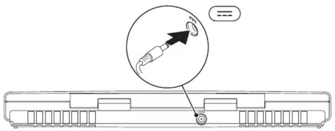
Connect the AC Adapter

WARNING: The AC adapter works with electrical outlets worldwide. However, power connectors and power strips vary among countries. Using an incompatible cable or improperly connecting the cable to a power strip or electrical outlet may cause fire or equipment damage.
CHAPTER 1: SETTING UP YOUR LAPTOP
Press the Power Button

natural_image
Line drawing of a laptop keyboard with a circular icon showing a download or download process (no text or symbols)CHAPTER 1: SETTING UP YOUR LAPTOP
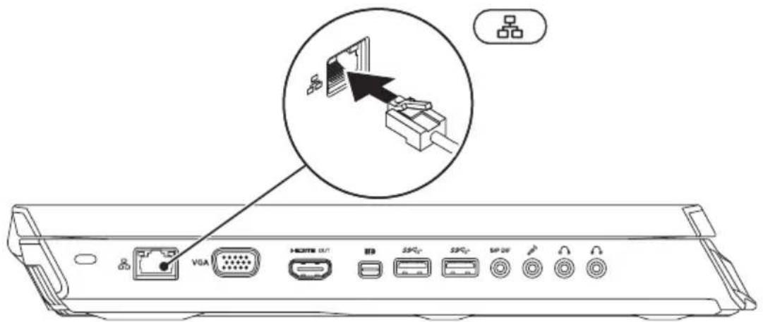
Connect the Network Cable (Optional)
CHAPTER 1: SETTING UP YOUR LAPTOP
Set Up Microsoft Windows
Your computer is preconfigured with the Microsoft Windows operating system. To set up Windows for the first time, follow the instructions on the screen. These steps are mandatory and may take some time to complete. The Windows setup screens will take you through several procedures including accepting license agreements, setting preferences, and setting up an Internet connection.

CAUTION: Do not interrupt the operating system's setup process. Doing so may render your computer unusable and you will need to reinstall the operating system.

NOTE: For optimal performance of your computer, it is recommended that you download and install the latest BIOS and drivers for your computer available at support.dell.com.

NOTE: For more information on the operating system and features, see support.dell.com/MyNewDell.

NOTE: It is recommended that you create a full system backup as soon as you set up Microsoft Windows.
CHAPTER 1: SETTING UP YOUR LAPTOP
Set Up WirelessHD (Optional)
The WirelessHD feature allows you to share high-definition video from your computer display to a TV without the use of cables. To set up WirelessHD, use a WirelessHD kit. For instructions on setting up WirelessHD, see the document that shipped with your WirelessHD kit.

NOTE: The WirelessHD kit does not ship with your computer and must be purchased separately.
If your computer supports the WirelessHD feature, the WiHD Application Controller icon will be available on the Windows desktop.


NOTE: You may have to set up WirelessHD kit before you set up WirelessHD. For more information on setting up the WirelessHD kit, see the document that shipped with the WirelessHD kit.
To set up WirelessHD:
- Turn on your computer.
- Ensure that wireless is enabled on your computer.
- Double-click the WiHD Application Controller icon on the desktop. The WirelessHD Application Controller window appears.
- Follow the instructions on screen.
Set Up Wireless Display (Optional)
NOTE: The wireless display feature may not be supported on all computers. For information about the hardware and software requirements for setting up wireless display, see www.intel.com.
NOTE: The wireless display feature is available on your computer only if you ordered an Intel Wi-Fi WLAN card and nVidia graphics card with Optimus technology or AMD Radeon graphics card at the time of purchase.
NOTE: It is recommended to use WirelessHD instead of wireless display for graphic-intense applications such as high-definition gaming. For more information, see "Set Up WirelessHD (Optional)" on page 16.
The Intel wireless display feature allows you to share your computer display to a TV without the use of cables. You must connect a wireless display adapter to your TV before setting up wireless display.
NOTE: The wireless display adapter does not ship with your computer and must be purchased separately.
NOTE: For information on setting up the wireless display, see the document that shipped with the wireless display adapter.
CHAPTER 1: SETTING UP YOUR LAPTOP
Connect to the Internet (Optional)
Setting Up a Wired Connection
- If you are using a dial-up connection, connect the telephone line to the optional external USB modem and to the telephone wall jack before you set up your Internet connection.
- If you are using a DSL or cable/satellite modem connection, contact your ISP or cellular telephone service for setup instructions.
To complete setting up your wired Internet connection, follow the instructions in "Setting Up Your Internet Connection" on page 20.
CHAPTER 1: SETTING UP YOUR LAPTOP
Setting Up a Wireless Connection

NOTE: To set up your wireless router, see the documentation that shipped with your router.
Before you can use your wireless Internet connection, you need to connect to your wireless router.
To set up your connection to a wireless router:
- Ensure that wireless is enabled on your computer.
- Save and close any open files, and exit any open programs.
- Click Start → Control Panel.
- In the search box, type network, and then click Network and Sharing Center→ Connect to a network.
- Follow the instructions on the screen to complete the setup.
CHAPTER 1: SETTING UP YOUR LAPTOP
Setting Up Your Internet Connection
ISPs and ISP offerings vary by country. Contact your ISP for offerings available in your country.
If you cannot connect to the Internet but have successfully connected in the past, the Internet Service Provider (ISP) might have a service outage. Contact your ISP to check the service status, or try connecting again later.
Have your ISP information ready. If you do not have an ISP, the Connect to the Internet wizard can help you get one.
- Save and close any open files, and exit any open programs.
- Click Start → Control Panel.
- In the search box, type network, and then click Network and Sharing Center→ Set up a new connection or Network→ Connect to the Internet.
The Connect to the Internet window appears.
NOTE: If you do not know which type of connection to select, click Help me choose or contact your ISP.
- Follow the instructions on the screen and use the setup information provided by your ISP to complete the setup.

-XXVXOI 3:60XXX47A3
[Unreadable Text]
CHAPTER 2: GETTING TO KNOW YOUR LAPTOP
flowchart
graph TD
    A["User"] --> B["Node 1"]
    A --> C["Node 2"]
    A --> D["Node 3"]
    A --> E["Node 4"]
    A --> F["Node 5"]
    A --> G["Node 6"]
    A --> H["Node 7"]
    A --> I["Node 8"]
    A --> J["Node 9"]
    A --> K["Node 10"]
    A --> L["Node 11"]
    A --> M["Node 12"]
    A --> N["Node 13"]
    A --> O["Node 14"]
    A --> P["Node 15"]
    A --> Q["Node 16"]
    A --> R["Node 17"]
    A --> S["Node 18"]
    A --> T["Node 19"]
    A --> U["Node 20"]
    A --> V["Node 21"]
    A --> W["Node 22"]
    A --> X["Node 23"]
    A --> Y["Node 24"]
    A --> Z["Node 25"]
    A --> AA["Node 26"]
    A --> AB["Node 27"]
    A --> AC["Node 28"]
    A --> AD["Node 29"]
    A --> AE["Node 30"]
    A --> AF["Node 31"]
    A --> AG["Node 32"]
    A --> AH["Node 33"]
    A --> AI["Node 34"]
    A --> AJ["Node 35"]
    A --> AK["Node 36"]
    A --> AL["Node 37"]
    A --> AM["Node 38"]
    A --> AN["Node 39"]
    A --> AO["Node 40"]
    A --> AP["Node 41"]
    A --> AQ["Node 42"]
    A --> AR["Node 43"]
    A --> AS["Node 44"]
    A --> AT["Node 45"]
    A --> AU["Node 46"]
    A --> AV["Node 47"]
    A --> AW["Node 48"]
    A --> AX["Node 49"]
    A --> AY["Node 50"]
CHAPTER 2: GETTING TO KNOW YOUR LAPTOP
This chapter provides information about your new laptop to familiarize you with its various features, and get you up and running quickly.
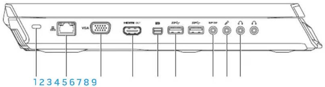
Left View Features
CHAPTER 2: GETTING TO KNOW YOUR LAPTOP
1 Security cable slot — Attaches a commercially available security cable to the computer.
NOTE: Before you buy a security cable, ensure that it fits into the security cable slot on your computer.

2 Network connector — Connects your computer to a network or broadband device.

3 VGA VGA connector — Connects your computer to a monitor or projector.

4 HDMI output connector — Connects to a TV for both multi-channel digital audio and video signals.
NOTE: For a monitor without built-in speakers, only the video signal will be read.

5 Mini-DisplayPort connector — Connects your computer to external DisplayPort monitors and projectors.
NOTE: The mini-DisplayPort connector also connects to a VGA connector through an optional mini-DisplayPort adapter. You can purchase the VGA cable and the mini-DisplayPort adapter at www.dell.com.
CHAPTER 2: GETTING TO KNOW YOUR LAPTOP
6 SS←USB 3.0 connectors (2) — Provide faster data transmission between your computer and USB devices.
7 S/P DIF Audio-out/Headphone/S/PDIF connector — Connects to amplifiers, speakers, or TVs for digital audio output. Can also be used to connect to a pair of headphones, powered speakers, or sound system.
NOTE: Use the S/PDIF adapter that shipped with your computer, to connect a TOSLINK optical cable.
8 Microphone connector — Connects to a microphone or inputs signal for use with audio programs.
9 📄 Headphone connectors (2) — Connect to a pair of headphones or to a powered speaker or sound system.
CHAPTER 2: GETTING TO KNOW YOUR LAPTOP
Right View Features

1 Optical drive — Plays or records only standard-size (12 cm) CDs, DVDs, and Blu-ray Discs (optional). Ensure that the side with print or writing is facing upward when inserting discs. For more information, see "Using the Optical Drive" on page 45.
2 9-in-1 Media Card Reader — Provides a fast and convenient way to view and share digital photos, music, videos, and documents.
3 USB 2.0 connectors (2) — Connect to USB devices, such as a mouse, keyboard, printer, external drive, or MP3 player.
CHAPTER 2: GETTING TO KNOW YOUR LAPTOP
4 eSATA/USB combo connector with USB PowerShare — Connects to eSATA compatible storage devices (such as external hard drives or optical drives) or USB devices (such as a mouse, keyboard, printer, external drive, or MP3 player).
The USB Powershare feature allows you to charge USB devices when the computer is powered on/off or in sleep state.
NOTE: Certain USB devices may not charge when the computer is powered off or in sleep state. In such cases, turn on the computer to charge the device.
NOTE: You can enable or disable the option of charging the USB devices when the computer is powered off or in sleep mode through the BIOS settings.
NOTE: If you turn off your computer while charging a USB device, the device stops charging. To continue charging, disconnect the USB device and connect it again.
NOTE: The USB PowerShare is automatically shut off when only 10% of the total battery life remains.
5 HDMI -HDMI-input connector — Connects to the HDMI-output connector on your video device such as a DVD player, camcorder, or gaming device.
NOTE: The HDMI-input connector works only when the computer is on.
CHAPTER 2: GETTING TO KNOW YOUR LAPTOP
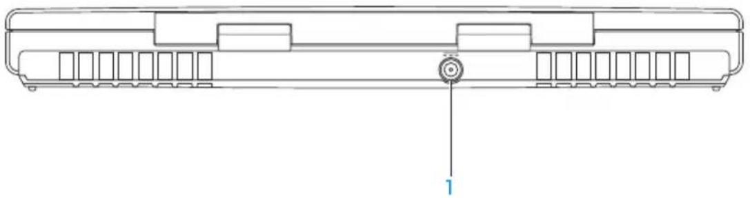
Back View Features
natural_image
Technical line drawing of a mechanical component with a central bolt and side slots (no text or symbols)1 AC adapter connector — Connects to an AC adapter to power the computer and charge the battery.
CHAPTER 2: GETTING TO KNOW YOUR LAPTOP
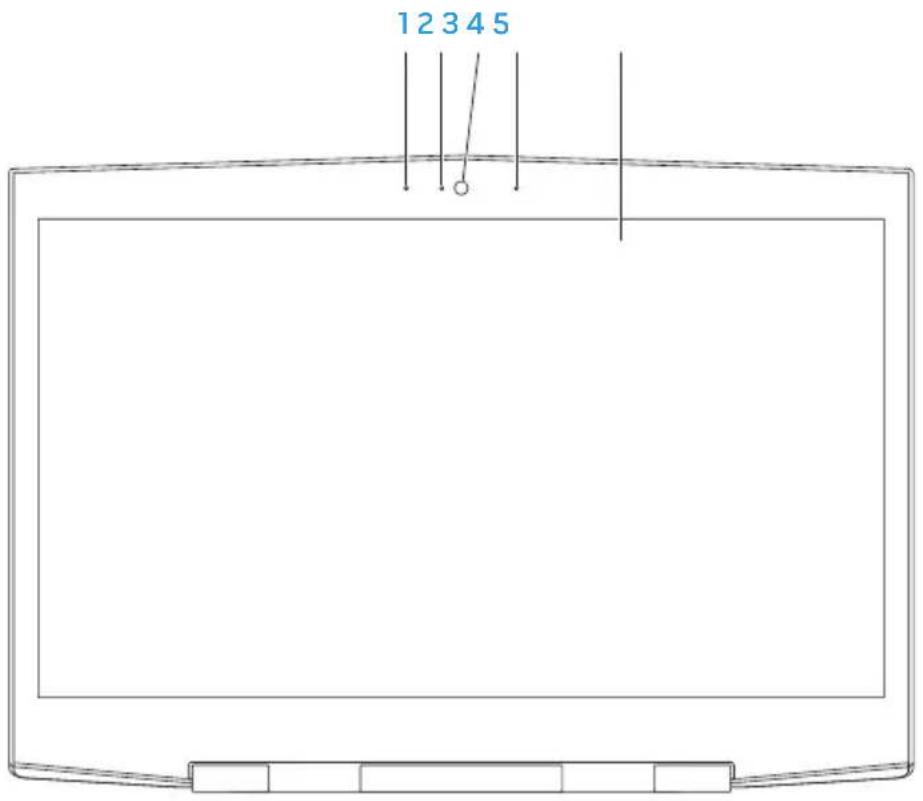
Display Features
CHAPTER 2: GETTING TO KNOW YOUR LAPTOP
1 Left digital-array microphone — Combines with the right digital-array microphone to provide high quality sound for video chatting and voice recording.
2 Camera activity indicator — Indicates if the camera is on or off. A solid blue light indicates camera activity.
3 Camera — Built-in camera for video capture, conferencing, and chat.
4 Right digital-array microphone — Combines with the left digital-array microphone to provide high quality sound for video chatting and voice recording.
5 Display — Your display can vary based on selections you made when purchasing your computer.
Your computer may support 3D display if you selected this option at the time of purchase.
NOTE: If you experience discomfort while viewing 3D display, stop viewing the display, remove your 3D glasses, and take rest.
CHAPTER 2: GETTING TO KNOW YOUR LAPTOP
Computer Base and Keyboard Features

CHAPTER 2: GETTING TO KNOW YOUR LAPTOP
1 Status lights (3) — Indicate if the Scroll Lock, Caps Lock, or Number Lock lights are turned on or off. For more information, see "Status Lights" on page 32.
2 Keyboard — The backlit keyboard provides visibility in dark environments by illuminating all symbols on the keys.
3 Touch pad buttons (2) — Provide left-click and right-click functions like those on a mouse.
4 Touch pad — Provides the functionality of a mouse to move the cursor, drag or move selected items, and left-click by tapping the surface.
5 Media control keys (9) — Press the keys to perform the associated action. For more information, see "Media Control Keys" on page 33.
6 Power button — Turns the computer on or off when pressed. For more information, see "Power Button" on page 34.
CHAPTER 2: GETTING TO KNOW YOUR LAPTOP
Status Lights
The three status lights are located at the top-left side of the keyboard. For the exact location, see "Computer Base and Keyboard Features" on page 30.

Scroll Lock Light
Turns on when the scroll lock option is on.

Caps Lock Light
Turns on when the keyboard is in Caps Lock mode. In this mode, all characters you type are in uppercase.

Number Lock Light
Turns on when the keyboard is in Num Lock mode. In this mode, the embedded numeric keypads can be used.
CHAPTER 2: GETTING TO KNOW YOUR LAPTOP
Media Control Keys
The media control keys are located at the top-right side of the keyboard. For the exact location, see "Computer Base and Keyboard Features" on page 30. To activate, press the desired keys. The keys will illuminate temporarily to confirm your selection.
Decrease volume
Increase volume
Mute the sound
Rewind or Play previous track
|| Play or Pause
| Fast Forward or Play next track
Eject
Wireless Control - Switch wireless communications on/off
(for more information, see "Using the Wireless Control" on page 46)
Alienware Command Center
(for more information, see "Alienware Command Center" on page 40)
CHAPTER 2: GETTING TO KNOW YOUR LAPTOP
Power Button
You can program this button to perform actions like shutting down the operating system or entering the standby mode. For details on how to program this button, see Power Options in the control panel of Microsoft Windows operating system.
The power button is located in the center of the hinge cover. For the exact location, see "Computer Base and Keyboard Features" on page 30.
The color of the AlienHead rim indicates the power status. The color indicating the power status can be changed using the AlienFX software.
CHAPTER 2: GETTING TO KNOW YOUR LAPTOP

On AC adapter:
Blue or custom AC-color The battery is fully charged.
Blue or custom AC-color fading into amber or custom battery-color
The computer is turned off or on and the battery is charging.
Blue or custom AC-color fading into black
The computer is in standby mode.
On battery:
Amber or custom battery-color The battery is fully charged.
Amber or custom battery-color fading into black
The computer is in standby mode.
Blinking Amber or custom battery-color
The battery charge is low.
For more details on standby and hibernate mode, see Power Options in the control panel of your Microsoft Windows operating system.
CHAPTER 2: GETTING TO KNOW YOUR LAPTOP
Function Keys

NOTE: Depending on the configuration of the laptop you purchased, some of the function keys may have no associated tasks.
The

FI – Suspend Mode
Press

F2 — Check Battery Status
Press

F3 – Mute on/off
Press

F4 – Increase Display Brightness
Press
CHAPTER 2: GETTING TO KNOW YOUR LAPTOP

F5 – Decrease Display Brightness
Press

F6 – Display Mode
Press

F7 – Switchable Graphics Toggle
Press

F8 – External HDMI Input Toggle
Press

F9 – Camera on/off
Press

F10 – Microsoft Mobility Center on/off
Press
CHAPTER 2: GETTING TO KNOW YOUR LAPTOP

F11 – AlienFX on/off
Press

F12 – Touch Pad on/off
Press

-XXVNI 3: GDXN/AGI EXCA
CHAPTER 3: USING YOUR LAPTOP

flowchart
graph TD
    A["Satellite"] --> B["World"]
    B --> C["Global Network"]
    C --> D["Satellite"]
    D --> E["Earth"]
    E --> F["Global Network"]
    F --> G["Satellite"]
    G --> H["World"]
    H --> I["Global Network"]
    I --> J["Satellite"]
    J --> K["Earth"]
    K --> L["Global Network"]
    L --> M["Satellite"]
    M --> N["World"]
    N --> O["Global Network"]
    O --> P["Satellite"]
    P --> Q["Earth"]
    Q --> R["Global Network"]
    R --> S["Satellite"]
    S --> T["World"]
    T --> U["Global Network"]
    U --> V["Satellite"]
    V --> W["Earth"]
    W --> X["Global Network"]
    X --> Y["Satellite"]
    Y --> Z["World"]
CHAPTER 3: USING YOUR LAPTOP
Alienware Command Center
The Alienware Command Center gives you access to Alienware's exclusive software and is a continuously upgradable control panel. As Alienware releases new programs, they download directly into the Command Center allowing you to build a library of system management, optimization, and customization tools. You can access Alienware Command Center by pressing 📂 the media control keys. See "Media Control Keys" on page 33.
Connecting External Displays
If you want to enjoy your computing environment on a bigger scale visually, or extend your desktop area, you can connect an external display such as a standalone monitor, an LCD TV, or a projector.
Connecting a Display
Use the appropriate cable based on the connectors available on your computer and display. Refer to the following table to identify the connectors on your computer and display.

NOTE: When connecting to a single display, connect the display to ONLY ONE of the connectors on your computer.
CHAPTER 3: USING YOUR LAPTOP
Connection Type Computer Cable Display
| VGA-to-VGA(VGA cable) |  |  |  |
| HDMI-to-HDMI(HDMI cable) |  |  | 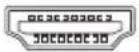 |
| Mini-DisplayPort-to-DisplayPort(Mini-DisplayPort-to-DisplayPort adapter + DisplayPort Cable) |  |  | 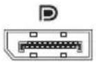 |
| Mini-DisplayPort-to-DVI (Mini-DisplayPort-to-DVI adapter + DVI cable) |  | 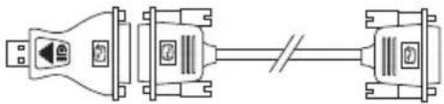 | 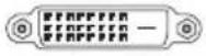 |
CHAPTER 3: USING YOUR LAPTOP
NOTE: You can purchase the mini-DisplayPort-to-DisplayPort and mini-DisplayPort-to-DVI adapters at www.dell.com.
- Turn off your laptop.
- Turn off the display and disconnect it from the power supply.
- Connect one end of the display cable to the VGA, mini-DisplayPort, or HDMI connector on your Alienware laptop.
- Connect the other end of the cable to the same connector on your display.
- If necessary, connect one end of the power cable to the display's power connector.
- Connect the other end of the power cable to a grounded three-prong power strip or wall outlet.
- Turn on your laptop, and then turn on your display.
Extending the Desktop
- With the external display connected, right-click on the desktop and select Personalize.
- Select Connect to a projector or other external display in the upper left portion of the screen.
- Click Connect Display.
-
Select from the below options that appear on the screen:
-
Duplicate my display on all displays (mirrored)
• Show different parts of my desktop on each display (extended)
• Show my desktop on the external display only -
Click Apply to apply your changes and then click OK to exit the Display Settings control panel.
CHAPTER 3: USING YOUR LAPTOP
Using Removable Media and Cards
Observe the safety measures below:
CAUTION: Inserting a blank card upside down may damage your laptop.
When no Media Card is inserted into the Media Card slot, ensure that the blank card that shipped with your laptop is inserted in the unused slot. The blank card protects the unused slot from dust and other particles. When inserting a blank card, ensure that the correct side is on the top (indicated by an arrow mark on some blank cards). For information on the media cards supported, see "Specifications" on page 103.
CHAPTER 3: USING YOUR LAPTOP
Using the Optical Drive
Your laptop has a slot load optical drive. Depending on the configuration ordered, your laptop may have one of the following drive types. These logos are used to indicate each drive's capabilities and media compatibility.
DVD±R/W DVD±R/W drive can read CD-ROM, CD-R, CD-R/W, DVD, DVD+R/W,
and DVD-R/W media.

Blu-ray Disc
Combo/Triple
Layer (optional)
Blu-ray drive can read CD-ROM, CD-R, CD-R/W, DVD, DVD+R/W, DVD-R/W, DVD+R, BD-ROM media.
It can also record to CD-R, CD-R/W, DVD+R/W, DVD-R/W, DVD+R media.

CHAPTER 3: USING YOUR LAPTOP
Using the Integrated Camera
FastAccess Facial Recognition
Your computer may have the FastAccess facial recognition feature. This feature helps keep your Alienware computer secure by using the unique appearance of your face to verify your identity and automatically supply login information that you would normally enter manually, such as a user ID and password for a Windows account or a secure web site. For more information, click Start → Programs → FastAccess.
Turning the Camera On and Off
Press the key combination
Using the Wireless Control
The wireless control allows you to quickly turn all of your wireless radios (Bluetooth, WLAN, and WWAN) off, such as when you are asked to disable all wireless radios on an airplane flight. Press (p) on the media control keys to turn on all radios. Press (p) again to return your wireless radios to their respective states they were in before you pressed the wireless key (p) the first time.
CHAPTER 3: USING YOUR LAPTOP
Battery Pack
Your laptop is equipped with a high-energy rechargeable lithium ion (Li-ion) battery pack. Battery life will vary depending on your laptop configuration, model, applications installed, power management settings, and features used. As with all batteries, the maximum capacity of this battery will decrease with time and usage.
The battery meter lights on the battery pack indicate the charge level of the battery. When you press the battery meter once, the charge level lights illuminate. Each of the five lights represent approximately 20% of the total battery charge. For example, if four lights turn on, there is 80% of battery charge remaining and if no lights turn on, there is no charge remaining in the battery.

natural_image
Isometric line drawing of a computer chassis with ventilation slots and a labeled component (no text or symbols beyond the number 1)1 Battery Meter
CHAPTER 3: USING YOUR LAPTOP
Power Management
Understanding Power Consumption
In order to fully utilize the power of your battery, it would be a good idea for you to spend some time acquiring a basic understanding of the power management concept from your operating system.
You can use the power options in your operating system to configure the power settings on your computer. The Microsoft Windows operating system installed on your computer provides three default options:
- Balanced — Offers full performance when you need it and saves power during periods of inactivity.
- Power Saver — Saves power on your computer by reducing system performance to maximize the life of the computer and by reducing the amount of energy consumed by your computer over its lifetime.
- High Performance — Provides the highest level of system performance on your computer by adapting processor speed to your activity and by maximizing system performance.
Customizing Your Power Settings
- Click Start → Control Panel.
- Click All Control Panel Items.
- Double-click the Power Options icon.
- Select a power plan from the options shown. To customize specific settings, click Change plan settings next to the selected power plan.
Reducing Power Consumption
Although your laptop (together with the operating system) is capable of power conservation, there are measures you can take to reduce the power consumption:
- Lower the intensity of the display backlight. A very bright screen translates to higher power usage.
- Use the Go Dark option in the Alienware Command Center.
CHAPTER 3: USING YOUR LAPTOP
nVidia Optimus Technology (Optional)

NOTE: The nVidia optimus technology is not supported on computers that use nVidia 3D vision.
Your Alienware M17x laptop is equipped with the nVidia Optimus technology. The Optimus technology is designed to maximize performance and user experience on your computer, while minimizing the impact on battery life. It enables you to combine the graphic processing capability of the integrated Intel graphic processing unit (GPU) with the discrete nVidia GPUv while running graphic-intensive applications such as 3-D games. The nVidia GPU is turned on only for preset applications and thus extends the battery life.
The Optimus technology is enabled through an application profile. When an application is launched, the video drivers check to see if the application has a profile associated with it.
- If an application profile exists, the nVidia GPU is turned on and the application runs in performance mode. The nVidia GPU is turned off automatically when the application is closed.
- If an application profile does not exist, the integrated Intel GPU is used.
The default list of application profiles is updated frequently by nVidia and is automatically downloaded to your computer when you are connected to the Internet.
CHAPTER 3: USING YOUR LAPTOP
You can also create application profiles for any application on your computer. This may be required for newly released games or applications that do not have a default application profile.
Changing the Application Profile Settings
- Right-click on the desktop and select NVIDIA Control Panel.
- In the NVIDIA Control Panel window, click 3D Settings to expand the selection (if not already expanded) and then click Manage 3D Settings.
- In the Program Settings tab, click Add and browse to select the application's executable file (.exe). Once added, you can change the settings for that application.
To change the settings for a specific application, locate the application in the Select a program to customize: list and make the desired changes.

NOTE: For more information on the nVidia control panel options and settings, click Help.
CHAPTER 3: USING YOUR LAPTOP
Free Fall Sensor
Free fall sensor protects your computer hard drive from possible damage, by detecting a free fall state caused by accidentally dropping the computer. When a free fall state is detected, the hard drive is placed in a safe state to protect against damage to the read/write head and possible data loss. Your hard drive returns to normal operation, when the free fall state is no longer detected.
CHAPTER 3: USING YOUR LAPTOP
Configuring the BIOS
System Setup
The System Setup options allow you to:
- Change the system configuration information after you add, change, or remove any hardware in your laptop.
- Set or change a user-selectable option.
• View the installed amount of memory or set the type of hard drive installed.
Before you use System Setup, it is recommended that you write down the current System Setup information for future reference.

CAUTION: Do not change the settings in System Setup unless you are an expert computer user. Certain changes can cause your computer to work incorrectly.
CHAPTER 3: USING YOUR LAPTOP
Entering System Setup
- Turn on (or restart) your laptop.
NOTE: Keyboard failure may result when a key on the keyboard is held down for extended periods of time. To avoid possible keyboard failure, press and release
2. While the laptop is booting, press
If an error occurs during Power On Self Test (POST), you may also enter the BIOS Setup Utility by pressing
NOTE: If you wait too long and the operating system logo appears, continue to wait until you see the Microsoft Windows desktop, then shut down your laptop and try again.
System Setup Screens
The BIOS Setup Utility window displays current or changeable configuration information for your laptop. Information is divided into five menus: Main, Advanced, Security, Boot, and Exit.
Key functions appear at the bottom of the BIOS Setup Utility window and lists keys and their functions within the active field.
System Setup Options
NOTE: Depending on your computer and installed devices, the items listed in this section may not appear, or may not appear exactly as listed.
NOTE: For the updated system setup information, see the Service Manual at support.dell.com/manuals.
Main Menu
| System Time (hh:mm:ss) | Displays the system time. |
| System Date (mm/dd/yyyy) | Displays the system date. |
| Alienware | Displays the model number of your computer. |
| Service Tag | Displays the service tag of your computer. |
| BIOS Version | Displays the BIOS version. |
| EC Version | Displays the EC firmware version. |
| ME Version | Displays the Intel ME firmware version. |
| Sandy Bridge Version | Displays the Sandy Bridge version. |
CHAPTER 3: USING YOUR LAPTOP
Main Menu
| CPU | Displays the type of processor installed. |
| CPU Frequency | Displays the speed of the processor. |
| CPU L3 Cache | Displays the processor cache size. |
| CPUID | Displays the ID of the processor. |
| Integrated Graphics | Displays the integrated graphics. |
| Discrete Graphics 1 | Displays the primary discrete graphics. |
| Discrete Graphics 2 | Displays the secondary discrete graphics. |
| Total Memory | Displays the total memory available in your computer. |
| Memory Bank 0 | Displays the memory size installed in DIMM 0. |
| Memory Bank 1 | Displays the memory size installed in DIMM 1. |
| SATA Hard Drive | Displays the installed SATA hard drive model. |
CHAPTER 3: USING YOUR LAPTOP
Advanced Menu
| Intel SpeedStep | Allows you to enable or disable the Intel SpeedStep technology. Disabling this feature may improve performance, but will greatly reduce battery life. |
| Virtualization | Allows you to enable or disable the Intel Virtualization technology. |
| USB Emulation | Allows you to enable or disable the USB emulation feature. This feature defines how the BIOS, in the absence of a USB-aware operating system, handles USB devices. USB emulation is always enabled during POST. |
| NOTE: You cannot boot any type of USB device (floppy, hard drive, or memory key) when this option is off. | |
| USB Wake Support | Allows you to enable USB devices to wake the computer from standby or to disable the USB wake support feature. |
| NOTE: If USB Powershare is enabled, a device connected to the USB Powershare connector may not wake the computer. |
CHAPTER 3: USING YOUR LAPTOP
Advanced Menu
| USB Power Share | Allows you to charge USB devices when the computer is turned off or in standby mode.AC Only: Charge USB devices when connected to AC adapter only.AC and Battery: Charge USB devices when connected to AC adapter and when the computer is running on battery Cooperative. Disabled: Disables USB PowerShare. |
| Integrated Network | Allows you to enable or disable the on-board LAN controller Cooperative. Disabled: Internal LAN is disabled and is not visible to the operating system. Enabled: Internal LAN is enabled. |
| High Definition Audio | Allows you to enable or disable the internal high definition audio device Cooperative. Disabled: The internal audio device is disabled and is not visible to the operating system. Enabled: The internal audio device is enabled. |
| SD Card Reader | Allows you to enable or disable the internal SD card reader. |
CHAPTER 3: USING YOUR LAPTOP
Advanced Menu
| CPU Turbo Mode | Allows you to enable or disable the Intel CPU turbo mode performance option. |
| Performance Menu | Allows you to configure fields in the Performance Options sub-menu (for more information, see “Performance Options Sub-Menu” on page 60). |
| Extended ICC | Allows you to configure fields in the Extended ICC sub-menu (for more information, see “Extended ICC Sub-Menu” on page 62). |
| SATA Operation | Allows you to configure the operating mode of the integrated SATA hard drive controller.AHCI: SATA is configured for AHCI mode.RAID: STAT is configured for RAID mode. |
| SATA HARD DRIVE 1 | Displays the installed primary SATA hard drive model. |
| SATA HARD DRIVE 2 | Displays the installed secondary SATA hard drive model. |
CHAPTER 3: USING YOUR LAPTOP
Advanced Menu
| Adapter Warnings | Allows you to choose if the computer should display warning messages when you use AC adapters that are not supported by your computer. Disabled: BIOS will not detect unsupported AC adapters and will not display any message to screen. Enabled: BIOS will detect unsupported AC adapters and display an error to screen. |
| Charger Behavior | Allows you to enable or disable battery charging. |
| Primary Display | Allows you to choose a primary display. |
Performance Options Sub-Menu
| Overclocking Feature | Allows you to enable or disable the global overclocking feature. Disabled: The overclocking feature is disabled. Enabled: Displays additional overclocking options. |
| Processor Overclocking | Allows you to enable or disable the processor overclocking feature. |
Performance Options Sub-Menu
| Override Turbo settings | Allows you to override CPU turbo mode settings. |
| Long Duration Power Limit | Allows you to set the turbo mode power limit 1 value in watts. |
| Long Duration Time Window | Allows you to set the turbo mode time 1 value in seconds. |
| Set Short Duration Power Limit | Allows you to enable or disable short duration power limit. |
| Short Duration Power Limit Options | Allows you to set the turbo mode power limit 2 value in watts. |
| Memory Overclocking | |
| Memory Override Support | Allows you to enable or disable the memory override option support. Disabled: The memory override support is disabled. Enabled: Displays additional memory override support options. |
| Memory Voltage | Allows you to increase memory voltage. |
CHAPTER 3: USING YOUR LAPTOP
Performance Options Sub-Menu
| Memory FrequencyXMP DIMM Profile | Allows you to set memory frequency.Allows you to configure different XMP options. |
| Extended ICC Sub-Menu | |
| Use Watchdog Timer for ICC | Allows you to enable or disable the watchdog timer. |
| Turn off unused PCI/PCIe clocks | Allows you to enable or disable the PCI/PCIe clocks.·Disabled: All PCI/PCIe clocks are on.·Enabled: Empty PCI/PCIe clocks disabled. |
| Lock ICC RegistersClock_DIV-1S | Allows you to lock either static registers or all registers. |
| Clock_DIV-2S | Displays the clock settings for the Div-1S devices. |
| Clock_DIV-3 | Displays the clock settings for the Div-2S devices. |
| Clock_DIV-4 | Displays the clock settings for the Div-3 devices. |
| Clock_DIV-1NS | Displays the clock settings for the Div-4 devices. |
| Clock_DIV-2NS | Displays the clock settings for the Div-1NS devices. |
| Displays the clock settings for the Div-2NS devices. | |
CHAPTER 3: USING YOUR LAPTOP
Wireless Menu
| Bluetooth | Allows you to enable or disable the internal Bluetooth device. Disabled: The internal Bluetooth device is disabled and is not visible to the operating system. Enabled: The internal Bluetooth device is enabled. |
| Wireless Network | Allows you to enable or disable the internal wireless device. Disabled: The internal wireless device is disabled and is not visible to the operating system. Enabled: The internal wireless device is enabled. |
| DGX | Allows you to enable or disable the internal DGX device. |
| Wireless Switch/Hotkey | Allows you to disable all internal wireless devices. |
Security Menu
| SupervisorPassword | Displays if the supervisor password is clear or set. |
| User Password | Displays if the user password is clear or set. |
CHAPTER 3: USING YOUR LAPTOP
Security Menu
| Set Service Tag | Displays the service tag of the computer when the service tag is present. |
| Displays a field to input the service tag manually when the service tag is absent. | |
| Set Supervisor Password | Allows you to set the supervisor password. The supervisor password controls access to the system setup utility. |
| Set User Password | Allows you to set the user password. The user password controls access to the computer at boot. |
| Computrace | Allows you to enable or disable Computrace security feature. |
Boot Menu
Use the up or down arrow keys to change the boot device priority. You can choose from:
- Hard Drive
- USB Storage
- CD/DVD/BD
- Removal Devices
- Network
CHAPTER 3: USING YOUR LAPTOP
Exit Menu
| Exit Saving Changes | Allows you to exit System Setup and save your changes to CMOS. |
| Save Change Without Exit | Allows you remain in System Setup and save your changes to CMOS. |
| Exit Discarding Changes | Allows you to exit System Setup and load previous values from CMOS for all Setup items. |
| Load Optimal Defaults | Allows you to load default values for all Setup items. |
| Discard Changes | Allows you to load previous values from CMOS for all Setup items. |
CHAPTER 3: USING YOUR LAPTOP

-XXVX01 3: ACDAXVE-ACD XCV
LOCEV-VACI-57天式VACI
CHAPTER 4: INSTALLING AND REPLACING COMPONENTS

flowchart
graph TD
    A["Global Entity"] --> B["Earth"]
    A --> C["Mars"]
    A --> D["Mars-like Structure"]
    B --> E["Global Origin"]
    C --> F["Mars"]
    D --> G["Mars-like Structure"]
    E --> H["Global Origin"]
    F --> I["Mars"]
    G --> J["Mars-like Structure"]
    H --> K["Global Origin"]
    I --> L["Mars"]
    J --> M["Mars-like Structure"]
CHAPTER 4: INSTALLING AND REPLACING COMPONENTS
This chapter provides guidelines and instructions for increasing the processing power and storage space, by upgrading equipment. You can purchase components for your computer at www.dell.com or www.alienware.com.

NOTE: See the Service Manual at support.dell.com/manuals for installation instructions of all serviceable components. Parts purchased from Dell and Alienware will ship with specific replacement instructions.
Before You Begin
This section provides procedures for removing and installing the components in your laptop. Unless otherwise noted, each procedure assumes that the following conditions exist:
- You have performed the steps in "Turning Off Your Computer" and "Before Working Inside Your Computer" in this section.
- You have read the safety information that shipped with your computer.
- A component can be replaced or—if purchased separately—installed by performing the removal procedure in reverse order.
The procedures in this section may require the following tools:
• Small flat-blade screwdriver
• Phillips screwdriver
CHAPTER 4: INSTALLING AND REPLACING COMPONENTS
Turning Off Your Computer
CAUTION: To avoid losing data, save and close all open files and exit all open programs before you turn off your laptop.
- Save and close all open files and exit all open programs.
- Click Start → Shut Down.
The laptop turns off after the operating system shutdown process finishes.
- Ensure that the computer and any attached devices are turned off. If your computer and attached devices did not automatically turn off when you shut down your operating system, press and hold the power button for at least 8 to 10 seconds until the computer turns off.
CHAPTER 4: INSTALLING AND REPLACING COMPONENTS
Before Working Inside Your Computer
Use the following safety guidelines to help protect your computer from potential damage and to help to ensure your own personal safety.
WARNING: Before working inside your laptop, read the safety information that shipped with your computer. For additional safety best practices information, see the Regulatory Compliance Homepage at www.dell.com/regulatory_compliance.
CAUTION: Handle components and cards with care. Do not touch the components or contacts on a card. Hold a card by its edges. Hold a component such as a processor by its edges, not by its pins.
CAUTION: Only a certified service technician should perform repairs on your computer. Damage due to servicing that is not authorized by Dell is not covered by your warranty.
CAUTION: To avoid electrostatic discharge, ground yourself by using a wrist grounding strap or by periodically touching an unpainted metal surface (such as a connector on the back of the computer).
CAUTION: When you disconnect a cable, pull on its connector or on its pull-tab, not on the cable itself. Some cables have connectors with locking tabs; if you are disconnecting this type of cable, press in on the locking tabs before you disconnect the cable. As you pull connectors apart, keep them evenly aligned to avoid bending any connector pins. Also, before you connect a cable, ensure that both connectors are correctly oriented and aligned.
CHAPTER 4: INSTALLING AND REPLACING COMPONENTS
△ CAUTION: To avoid damaging the computer, perform the following steps before you begin working inside the computer.
- Ensure that the work surface is flat and clean to prevent the computer cover from being scratched.
- Turn off your computer (for more information, see "Turning Off Your Computer" on page 69).
CAUTION: To disconnect a network cable, first unplug the cable from your computer and then unplug the cable from the network device.
-
Disconnect all telephone or network cables from the laptop.
-
Press and eject any installed cards from the Media Card Reader.
-
Disconnect your computer and all attached devices from their electrical outlets.
CAUTION: To help prevent damage to the system board, you must remove the battery from the battery bay before you service the laptop.
-
Remove the battery from the battery bay (for more information, see "Replacing the Battery Pack" on page 72).
-
Press the power button to ground the system board.
CHAPTER 4: INSTALLING AND REPLACING COMPONENTS
Replacing the Battery Pack
This battery pack can easily be removed and replaced. Ensure that the laptop is properly shut down before changing the battery pack.

CAUTION: To avoid damage to the laptop, use only the battery designed for this particular Alienware laptop. Do not use batteries designed for other Alienware or Dell laptops.
To remove the battery pack:
- Follow the instructions in "Before You Begin" on page 68.
- Shut down the laptop.
- Turn the laptop over.
- Slide the battery latch to the unlock position as shown.
The battery pack pops up. - Remove the battery pack.
CHAPTER 4: INSTALLING AND REPLACING COMPONENTS

1 battery bay 3 battery pack
2 battery latch
To replace the battery pack, perform the removal steps in reverse order.
CHAPTER 4: INSTALLING AND REPLACING COMPONENTS
Upgrading or Replacing Memory
Your laptop is equipped with a configurable memory unit. The industry standard JEDEC PC3-10600 (DDR3) SODIMM memory module connectors are available for memory upgrade.

NOTE: If you purchased a dual-core processor, your computer supports only memory module connectors DIMM 1 and DIMM 2.

NOTE: The table below illustrates one possible way the system memory can be configured. You can also configure the system memory by installing memory modules in connectors DIMM 3 and DIMM 4.
| MemoryconnectorDIMM 1 | MemoryconnectorDIMM 2 | MemoryconnectorDIMM 3 | MemoryconnectorDIMM 4 | Total memory |
2 GB 2 GB —— 4 GB
2 GB 4 GB —— 6 GB
4 GB 4 GB —— 8 GB
8 GB 8 GB —— 16 GB
8 GB 8 GB 8 GB 8 GB 32 GB
CHAPTER 4: INSTALLING AND REPLACING COMPONENTS
Removing the Memory Module(s)

NOTE: Your computer supports up to four memory module connectors. You can access connectors DIMM 1 and DIMM 2 by removing the compartment door at the bottom of your computer. To upgrade memory module(s) in connectors DIMM 3 and DIMM 4, see the Service Manual at support.dell.com.
- Follow the instructions in "Before You Begin" on page 68.
- Remove the battery (see "Replacing the Battery Pack" on page 72).
- Remove the two screws that secure the compartment door to the computer base.
- Slide and lift the compartment door away from the computer.
CHAPTER 4: INSTALLING AND REPLACING COMPONENTS
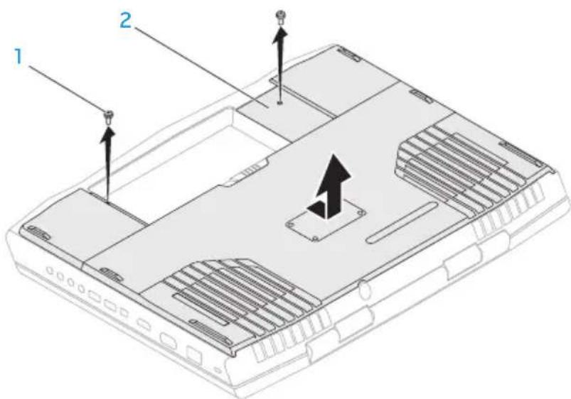
1 screws (2) 2 compartment door
- Use your fingertips to carefully spread apart the memory module connector's spring-locks until the module pops up.
- Remove the memory module.
CHAPTER 4: INSTALLING AND REPLACING COMPONENTS

1 memory module 4 notch
2 spring locks (2) 5 memory module connector
3 tab
To replace the memory modules, perform the removal steps in reverse order. While inserting the memory module into the connector align the notch on the memory module with the tab on the memory module connector.

NOTE: If you need to install memory modules in two connectors, install a memory module in the lower connector before you install a memory module in the upper connector.

NOTE: If the memory module is not installed properly, the computer may not boot.
CHAPTER 4: INSTALLING AND REPLACING COMPONENTS
Upgrading or Replacing the Hard Drive(s)
Your laptop is equipped with two hard drive sockets.
Removing the Hard Drive(s)
- Follow the instructions in "Before You Begin" on page 68.
- Remove the battery pack (see "Replacing the Battery Pack" on page 72).
- Remove the two screws that secure the compartment door to the computer base.
- Slide and lift the compartment door away from the computer.
CHAPTER 4: INSTALLING AND REPLACING COMPONENTS

1 screws (2) 2 compartment door
- Loosen the three captive screws on the primary hard-drive assembly (HDDO).
- Using the pull-tab, lift the primary hard-drive assembly to disconnect it from the connector on the system board.
- Lift the primary hard-drive assembly out of the computer base.
CHAPTER 4: INSTALLING AND REPLACING COMPONENTS

1 pull tab 3 captive screws (3)
2 primary hard-drive assembly
- Loosen the three captive screws on the secondary hard-drive assembly (HDD1).
- Using the pull tab, lift the secondary hard-drive assembly (HDD1) to disconnect it from the connector on the system board.
- Lift the secondary hard-drive assembly out of the computer base.
CHAPTER 4: INSTALLING AND REPLACING COMPONENTS

1 pull tab 3 captive screws (3)
2 secondary hard-drive assembly
CHAPTER 4: INSTALLING AND REPLACING COMPONENTS
- Remove the four screws that secure the hard drive to the hard-drive bracket.
- Lift the hard drive off the hard-drive bracket.

1 hard drive 3 screws (4)
2 hard-drive bracket
CHAPTER 4: INSTALLING AND REPLACING COMPONENTS
- Remove the interposer from the hard drive.
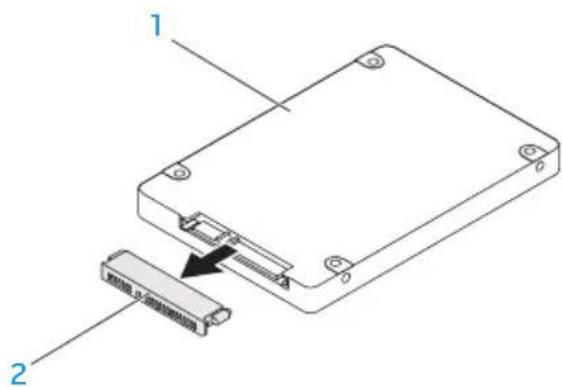
1 hard drive 2 interposer
To replace the hard drive(s), perform the removal steps in reverse order.
CHAPTER 4: INSTALLING AND REPLACING COMPONENTS

-XXVX01 3: XI50X60X70X80X9
CHAPTER 5: TROUBLESHOOTING

flowchart
graph TD
    A["World"] --> B["Asia"]
    A --> C["Europe"]
    B --> D["Global Network"]
    C --> D
    D --> E["China"]
    D --> F["Japan"]
    D --> G["USA"]
    D --> H["China & India"]
    D --> I["China & South Korea"]
    D --> J["China & Japan"]
    D --> K["China & Australia"]
    D --> L["China & Russia"]
    D --> M["China & Canada"]
    D --> N["China & Mexico"]
    D --> O["China & Argentina"]
CHAPTER 5: TROUBLESHOOTING
Basic Hints and Tips
- Computer does not power on: Is your AC adapter cable securely connected to a working electrical outlet? If connected to a power strip, ensure that the strip is actually working.
- Connections: Check all the cables to ensure that there are no loose connections anywhere.
- Power Savings: Ensure that your computer is not in hibernate or standby mode by pressing the power button for less than 4 seconds. The power status light will fade from blue to black while in standby mode; in hibernate mode it will be off.
- Brightness: Check and adjust the brightness of the display by pressing the key combinations
or . - Display Choice: Press the key combination
to ensure that the computer is not set to "External Only" display. - Use only the AC adapter that shipped with your laptop.
Backup and General Maintenance
- Always backup your important data on a regular basis and keep copies of your operating system and software safe. Do not forget to note the serial numbers if you are storing them outside of their original cases - for example, in a CD wallet.
- Run maintenance programs as often as you can. You may schedule these programs to run at times when you are not using your computer. You can use those provided with your operating system, or buy more powerful, dedicated programs to do so.
- Write down your passwords and keep them safe (away from your computer). This is especially important if you choose to password-protect your computer's BIOS and operating system.
- Document vital settings such as network, dialup, mail and Internet settings.
CHAPTER 5: TROUBLESHOOTING
When troubleshooting your computer, remember the following safety guidelines:
- Before touching any of the computer's internal components, touch an unpainted portion of the chassis. Doing so will safely discharge any static electricity, which could damage your computer.
- Turn off your computer and any connected peripherals.
- Disconnect any peripherals from your computer.
Things to check:
- Ensure that the AC adapter cable is properly connected between your computer and a grounded, three-prong power outlet. Ensure that the power outlet is working.
- Ensure the UPS or power strip is turned on (if applicable).
- If your peripheral devices (for example keyboard, mouse, printer, and so on) are not working, ensure that all connections are secure.
- If any computer components were added or removed before the problem began, check to see if you performed the installation or removal procedures properly.
- If an error message appears on the screen, write down the exact error message prior to calling Alienware Technical Support to aid in diagnosing and resolving your issue.
- If an error occurs in a specific program, see the program's documentation.
Software Diagnostic Tools Pre-Boot System Assessment (PSA)/Enhanced Pre-Boot System Assessment (ePSA)

NOTE: Your computer may have Pre-boot System Assessment (PSA) or Enhanced Pre-boot System Assessment (ePSA) pre-installed on your computer.
The computer runs the PSA/ePSA, a series of initial tests of your system board, keyboard, display, memory, hard drive, etc.
To invoke PSA/ePSA:
-
Turn on (or restart) your computer.
-
When the Alienware logo appears, press
immediately.

NOTE: If you wait too long and the operating system logo appears, continue to wait until you see the Microsoft Windows desktop; then, shut down your computer and try again.
- Select Diagnostics from the menu and press
.
CHAPTER 5: TROUBLESHOOTING
During the assessment, answer any questions that appear.
- If a failure is detected, the computer stops and beeps. To stop the assessment and restart the computer, press
; to continue to the next test, press ; to retest the component that failed, press . - If failures are detected during the PSA/ePSA, write down the error code(s) and contact Alienware (for more information, see "CONTACTING ALIENWARE" on page 123).
If the PSA/ePSA completes successfully, the following message appears "Do you want to run the remaining memory tests? This will take about 30 minutes or more. Do you want to continue? (Recommended)."
If you are experiencing memory issues, press
Press
Answers to Common Problems
System
The computer fails the POST
The Power On Self Test (POST) ensures that the computer meets all the necessary system requirements and that all hardware is working properly before starting the remainder of the boot process. If the computer passes the POST, the computer will continue to start normally. However, if the computer fails the POST, the computer will generate a single beep to indicate a general failure and an error message will be displayed. For assistance, contact Alienware Technical Support (see "CONTACTING ALIENWARE" on page 123).
The computer stops responding or a solid blue screen appears

CAUTION: You might lose data if you are unable to perform an operating system shutdown.
If you are unable to get a response by pressing a key on your keyboard or moving your mouse, press and hold the power button for at least 6 seconds until the computer turns off, then restart your computer.

NOTE: The chkdsk program may run when you restart the computer. Follow the instructions on the screen.
CHAPTER 5: TROUBLESHOOTING
A program stops responding or crashes repeatedly
End the program:
- Press
simultaneously. - Click the Applications tab and select the program that is no longer responding.
- Click End Task.
Check the software documentation.
If necessary, uninstall and then reinstall the program.
A program is designed for an earlier version of Microsoft Windows
Run the Program Compatibility Wizard:
The Program Compatibility Wizard configures a program so that it runs in an environment similar to an earlier version of Microsoft Windows operating system environments.
- Click Start → Control Panel → Programs → Programs and Features → Use an older program with this version of Windows.
- In the welcome screen, click Next.
- Follow the instructions on the screen.
CHAPTER 5: TROUBLESHOOTING
Other software problems
Back up your files immediately
Use a virus-scanning program to check the hard drive, or CDs
Save and close any open files or programs and shut down your computer through the Start menu
Scan the computer for spyware:
If you are experiencing slow computer performance, you frequently receive pop-up advertisements, or you are having problems connecting to the Internet, your computer might be infected with spyware. Use an anti-virus program that includes anti-spyware protection (your program may require an upgrade) to scan the computer and remove spyware.
Run the PSA/ePSA Diagnostics:
If all tests run successfully, the error condition is related to a software problem.
CHAPTER 5: TROUBLESHOOTING
Check the software documentation or contact the software manufacturer for troubleshooting information:
- Ensure that the program is compatible with the operating system installed on your computer.
- Ensure that your computer meets the minimum hardware requirements needed to run the software. See the software documentation for information.
- Ensure that the program is installed and configured properly.
- Verify that the device drivers do not conflict with the program.
- If necessary, uninstall and then reinstall the program.
Hard Drive Problems
Allow the computer to cool before turning it on
A hot hard drive may prevent the operating system from starting. Try allowing the computer to return to room temperature before turning it on.
Run Check Disk
- Click Start → Computer.
- Right-click Local Disk C:
- Click Properties→Tools→Check Now. If the User Account Control window appears, click Continue.
- Follow the instructions on the screen.
CHAPTER 5: TROUBLESHOOTING
Memory
Memory errors detected on startup
- Check memory modules for correct seating and orientation. Reseat the memory modules if applicable (see "Upgrading or Replacing Memory" on page 74).
- Computers using a dual-channel memory configuration require that memory modules be installed in pairs. If you require assistance, contact Alienware Technical Support (for more information, see "CONTACTING ALIENWARE" on page 123).
Display
If the display is blank

NOTE: If you are using a program that requires a higher resolution than your computer supports, it is recommended that you attach an external monitor to your computer.
The computer may be in a power saving mode:
Press a key on the keyboard or press the power button to resume normal operation.
Switch the video image:
If your computer is attached to an external monitor, press
Power
When you press the power button, the computer does not turn on
- If the AC adapter cable is connected to a surge protector or UPS, ensure that the surge protector or UPS is securely connected to an electrical outlet, is switched on and is working correctly.
- Check that the wall outlet is working properly by testing another device such as a radio or lamp that you know works. If the wall outlet is not working, contact an electrician or your power company for further assistance.
- If the problem persists, contact Alienware support (see "CONTACTING ALIENWARE" on page 123).
CHAPTER 5: TROUBLESHOOTING

-XXVNOI 3: VONO7 I0-27016
CHAPTER 6: SYSTEM RECOVERY

flowchart
graph TD
    A["Satellite"] --> B["World"]
    B --> C["Earth"]
    C --> D["Satellite"]
    D --> E["World"]
    E --> F["Earth"]
    F --> G["Satellite"]
    G --> H["World"]
    H --> I["Earth"]
    I --> J["Satellite"]
    J --> K["World"]
    K --> L["Earth"]
    L --> M["Satellite"]
    M --> N["World"]
    N --> O["Earth"]
    O --> P["Satellite"]
    P --> Q["World"]
    Q --> R["Earth"]
    R --> S["Satellite"]
    S --> T["World"]
    T --> U["Earth"]
    U --> V["Satellite"]
    V --> W["World"]
AlienRespawn
CAUTION: Using AlienRespawn permanently removes any programs or drivers installed after you received your computer. Create backup media of applications you need to install on your computer before using AlienRespawn. Use AlienRespawn only if System Restore did not resolve your operating system problem.
CAUTION: Although AlienRespawn is designed to preserve the data files on your computer, it is recommended that you backup your data files before using AlienRespawn.
You can use AlienRespawn to restore your hard drive to the operating state it was in when you purchased your computer, while preserving the data files.
AlienRespawn allows you to backup and restore your computer to an earlier operating state.
AlienRespawn Basic
To restore the factory image while preserving the data files:
- Turn off your computer.
- Disconnect all the devices connected to the computer (such as USB drive, printer, and so on) and remove any recently added internal hardware.
NOTE: Do not disconnect the AC adapter cable.
-
Turn on your computer.
-
When the Alienware logo appears, press
several times to access the Advanced Boot Options window.
NOTE: If you wait too long and the operating system logo appears, continue to wait until you see the Microsoft Windows desktop; then, shut down your computer and try again.
-
Select Repair Your Computer.
-
Select AlienRespawn and Emergency Backup from the System Recovery Options menu and follow the instructions on the screen.

NOTE: The restoration process may take an hour or more depending on the size of the data to be restored.

NOTE: For more information on AlienRespawn, see knowledge base article 353560 at support.dell.com.
Upgrading to AlienRespawn Professional
AlienRespawn provides additional features that allow you to:
- Backup and restore your computer based on file types
• Backup files to a local storage device - Schedule automated backups
To upgrade to AlienRespawn Professional:
- Double-click the AlienRespawn icon in the notification area of your desktop.
- Click Upgrade Now!
- Follow the instructions on the screen.
CHAPTER 6: SYSTEM RECOVERY
Dell DataSafe Online Backup (Optional)
NOTE: Dell DataSafe Online is supported only on Windows operating systems.
NOTE: A broadband connection is recommended for fast upload or download speeds.
Dell DataSafe Online is an automated backup and recovery service that helps protect your data and other important files from catastrophic incidents like theft, fire, or natural disasters. You can access the service on your computer using a password-protected account.
For more information, go to delldatasafe.com.
To schedule backups:
- Double-click the Dell DataSafe Online icon on the taskbar.
- Follow the instructions that appear on the screen.
My Dell Downloads
NOTE: My Dell Downloads may not be available in all regions.
Some of the software pre-installed on your new Dell computer do not include a backup CD or DVD. This software is available on the My Dell Downloads website. From this website you can download available software for reinstallation or create your own backup media.
To register and use My Dell Downloads:
- Go to DownloadStore.dell.com/media.
- Follow the instructions on the screen to register and download the software.
- Reinstall the software or create a backup media for future use.

-XXVXOI 3: XVXN-1 DFO-VWXN-IVXNGD
CHAPTER 7: SPECIFICATIONS

flowchart
graph TD
    A["Satellite"] --> B["World"]
    B --> C["Global Network"]
    C --> D["Satellite"]
    D --> E["Earth"]
    E --> F["Global Network"]
    F --> G["Satellite"]
    G --> H["World"]
    H --> I["Global Network"]
    I --> J["Satellite"]
    J --> K["Earth"]
    K --> L["Global Network"]
    L --> M["Satellite"]
    M --> N["World"]
    N --> O["Global Network"]
    O --> P["Satellite"]
    P --> Q["Earth"]
    Q --> R["Global Network"]
    R --> S["Satellite"]
    S --> T["World"]
    T --> U["Global Network"]
    U --> V["Satellite"]
    V --> W["Earth"]
    W --> X["Global Network"]
    X --> Y["Satellite"]
    Y --> Z["World"]
CHAPTER 7: SPECIFICATIONS
Computer Model
Alienware M17x-R3
Dimensions
Height
Front 44.5 mm (1.75 inches)
Back 45.0 mm (1.77 inches)
Width 410.0 mm (16.14 inches)
Depth 304.0 mm (11.97 inches)
Weight with 9-cell battery and optical drive (starting at)
4.26 kg (9.40 lb)
NOTE: The weight of your laptop will vary depending on the configuration ordered and the manufacturing variability.
Processor and System Chipset
Processor
- Intel Core i5
- Intel Core i7
L2 cache 256 KB
L3 cache up to 8 MB
Bus clock 100 MHz
System chipset Mobile Intel HM67 Express Chipset
SDRAM bus width one or two 64-bit channels of DDR3 memory up to 1333 MHz
Processor address bus width 32 bits
Processor data width 64 bits
BIOS SPI Flash Memory 32 Mbit
Graphics bus PCIe x16 bus
CHAPTER 7: SPECIFICATIONS
Memory
Connectors four internally-accessible DDR3 using JEDEC SODIMM sockets
Capacities 2 GB, 4 GB, and 8 GB
Memory type up to 1333 MHz unbuffered non-ECC dual-channel DDR3 configuration
Memory configurations 4 GB, 6 GB, 8 GB, 16 GB, and 32 GB possible
CHAPTER 7: SPECIFICATIONS
Ports and Connectors
Network adapter one RJ45 connector
USB two 4-pin USB 2.0 and 3.0 compliant connectors
eSATA/USB combo one 7-pin/4-pin eSATA/USB 2.0-compliant combo connector with PowerShare
HDMI input and output one 19-pin connector
Mini-DisplayPort one 20-pin connector
VGA one 15-hole connector
Audio two stereo headphones/speakers connectors
one microphone-in connector
S/PDIF one headphone/S/PDIF combo connector
Media Card Reader one 9-in-1 slot
CHAPTER 7: SPECIFICATIONS
Communications
Network adapter 10/100/1000 Mbps Ethernet LAN on system board
Wireless • one half Mini-Card slot
• one full Mini-Card slot
- Bluetooth; Wireless Display (optional); WirelessHD (optional)
Video
Video controller
Integrated Intel HD Graphics 3000
Discrete • NVIDIA GeForce GTX 460M
• AMD Radeon HD 6970M
• AMD Radeon HD 6870M
Video
Video memory
Integrated 512 MB dedicated video memory (for total system memory greater than 4 GB)
Discrete • 1.5 GB
1.0 GB
2.0 GB
External display support HDMI, Mini DisplayPort, VGA, WiDi (optional), and WirelessHD (optional)
Audio
Type High-Definition 5.1 surround sound audio
Controller IDT 92HD73 HDA codec
Speaker dual 8-ohms speakers in both the left and right speaker assembly
Internal speaker amplifier up to 5 W per channel; up to 10 W total power
CHAPTER 7: SPECIFICATIONS
Audio
Internal microphone support dual digital microphone in camera assembly
Volume controls program menus and keyboard media function keys
Hard-Drive Storage
Interface • SATA 2.0 (3Gb/s)
• Solid-State Drive (SSD)
Number of storage drives two
Hard drive
- two 2.5 inch SATA 2.0 (3Gb/s) hard drives
• one solid-state drive
CHAPTER 7: SPECIFICATIONS
Media Card Reader
Cards supported
- Secure Digital (SD) memory card
- Secure Digital Input/Output (SDIO) card
- Secure Digital Extended Capacity (SDXC) card
• MultiMedia Card (MMC)
• MultiMedia Card plus (MMC+) - Memory Stick
• Memory Stick PRO
• xD-Picture Card (type - M and type - H)
• Hi Density-SD (SDHD)
• Hi Capacity-SD (SDHC)
CHAPTER 7: SPECIFICATIONS
Display
Type • 17.3 inch HD+ WLED
• 17.3 inch FHD WLED
• 17.3 inch FHD 120 Hz WLED
- 17.3 inch FHD 120 Hz WLED with nVidia 3D vision support
Maximum resolution 1920 x 1080
Dimensions (active area)
Height 215 mm (8.46 inches)
Width 382 mm (15.04 inches)
Diagonal 439 mm (17.28 inches)
Refresh rate 60 Hz
Operating angle 0^ (closed) to 140^
Pixel pitch 0.2550 mm
Controls brightness can be controlled through keyboard shortcuts
CHAPTER 7: SPECIFICATIONS
Keyboard (Backlit)
Number of keys 82 (Korea, U.S., and Canada); 83 (Europe); 86 (Japan)
Backlight color RGB; colors can be changed by invoking the AlienFX application in the Alienware Command Center. For information, see "Alienware Command Center" on page 40.
Touch Pad
X/Y position resolution 240 cpi (graphics table mode)
Size
Height 54.00 mm (2.13 inches) sensor-active area Width 100.00 mm (3.94 inches) rectangle
Camera
Camera resolution 3.0 megapixel
Video resolution 2048 x 1536
Diagonal viewing angle 60°
CHAPTER 7: SPECIFICATIONS
Battery
9-cell "smart" lithium ion (92 Whr)
Height 22.00 mm (0.87 inches)
Width 233.00 mm (9.17 inches)
Depth 90.00 mm (3.54 inches)
Weight 0.52 kg (1.14 lb)
Voltage 11.10 VDC
Operating time battery operating time varies depending on operating conditions and can be significantly reduced under certain power-intensive conditions.
Life span (approximate) 300 discharge/charge cycles
Temperature range
Operating 0° to 50°C (32° to 122°F)
Storage -20^ to 60^ C ( -4^ to 140^ F)
Coin-cell battery CR-2032
CHAPTER 7: SPECIFICATIONS
AC Adapter
Type 150 W/240 W
Input voltage 100-240 VAC
Input current (maximum)
150 W 2.50 A
240 W 3.50 A
Input frequency 50-60 Hz
Output current
150 W 7.70 A (continuous)
240 W 12.30 A (continuous)
Output power
150 W 150 W
240 W 240 W
Rated output voltage 19.50 VDC
CHAPTER 7: SPECIFICATIONS
AC Adapter
Temperature range
Operating
150 W 0° to 35°C (32° to 95°F)
240 W 0° to 40°C (32° to 104°F)
Storage -40^ to 70^ C ( -40^ to 158^ F)
Connector types
DC connector 3-pin, 7.4 mm plug
AC connector 3-pin - C13 (150 W)
3-pin - C13 (240 W)
Computer Environment
Temperature range
Operating 0° to 35°C (32° to 95°F)
Storage -40^ to 65^ C ( -40^ to 149^ F)
Computer Environment
Relative humidity (maximum)
Operating 10% to 90% (non-condensing)
Storage 10% to 95% (non-condensing)
Maximum vibration (Using a random vibration spectrum that simulates user environment)
Operating 0.66 GRMS
Storage 1.3 GRMS
Maximum shock (Measured with hard drive in operating status and a 2-ms half-sine pulse for operating. Also measured with hard drive in head-parked position and a 2-ms half-sine pulse for storage)
Operating 110 G
Storage 160 G
Altitude (maximum)
Operating -15.2 to 3048 m (-50 to 10,000 ft)
Storage -15.2 to 10,668 m (-50 to 35,000 ft)
Airborne contaminant level G2 or lower as defined by ISA-S71.04-1985
CHAPTER 7: SPECIFICATIONS

VCTAVXF
APPENDIX
flowchart
graph TD
    A["Satellite"] --> B["World"]
    B --> C["Global Network"]
    C --> D["Satellite"]
    D --> E["Earth"]
    E --> F["Global Network"]
    F --> G["Satellite"]
    G --> H["World"]
    H --> I["Global Network"]
    I --> J["Satellite"]
    J --> K["Earth"]
    K --> L["Global Network"]
    L --> M["Satellite"]
    M --> N["World"]
    N --> O["Global Network"]
    O --> P["Satellite"]
    P --> Q["Earth"]
    Q --> R["Global Network"]
    R --> S["Satellite"]
    S --> T["World"]
    T --> U["Global Network"]
    U --> V["Satellite"]
    V --> W["Earth"]
    W --> X["Global Network"]
    X --> Y["Satellite"]
    Y --> Z["World"]
APPENDIX
GENERAL AND ELECTRICAL SAFETY PRECAUTIONS
Computer Setup
- Read all instructions marked on the product and in the documentation before operating your computer.
- Retain all safety and operating instructions.
- Never use this product near water or a heat source.
- Only set-up the computer on a stable work surface.
- Only operate the computer using the power source type indicated on the rating label.
- Never block or cover any openings or fans in the computer case. These are required for ventilation.
- Never insert objects of any kind into the ventilation openings.
- Ensure that your computer is properly grounded when in use.
- Do not attempt to connect your computer into an outlet that is not properly grounded.
- If an extension cord is used with your computer, ensure that the total ampere rating on the computer does not exceed the maximum rating on the extension cord.
Computer Use
- Route the power cable and all cables away from where people might walk or trip over them. Do not allow anything to rest on the power cable.
- Do not spill anything on or into your computer.
- To avoid electrical shock, always disconnect all power, modem and any other cables from the wall outlets before handling the computer.
Electrostatic Discharge (ESD) Warning
Electrostatic Discharge (ESD) can cause damage to internal system components if precautions are not taken. ESD is caused by static electricity and the damage caused is usually permanent.
Computer technicians wear a special wrist-strap that grounds them to the computer's case to prevent ESD damage. To reduce the chances of ESD damage:
- Turn off your computer's power and wait several minutes before starting to work.
• Ground yourself by touching the case of the computer. - Avoid walking around while replacing items inside the case, especially if you are on a carpet or during low temperature and low humidity.
- Touch only those items which must be replaced.
- If you have to remove peripheral cards for any reason, place them on the portion of the computer's case that was removed. Do not touch the edge connectors at the bottom of the card that connect to the system board.
APPENDIX
General Safety Precautions
- Mechanical Shock: Your computer should never be subjected to severe mechanical shocks. Careless handling of your computer may cause damage. Mechanical Shock is not covered by the warranty.
- Electrical Shock: If you do not open up your computer, there is nothing to worry about. Your computer protects itself against most irregularities in the power source.
When You Should Contact Alienware
- The battery, power cable or connector is damaged.
- Your computer has had liquid spilled into it.
- Your computer was dropped or the case was damaged.
- Normal operation of the computer does not occur when the operating instructions are followed.
Replacement Components or Accessories
It is only advised to use replacement parts or accessories recommended by Alienware.
CONTACTING ALIENWARE
For customers in the United States/Canada, call 1-800-ALIENWARE.

NOTE: If you do not have an active Internet connection, you can find contact information on your purchase invoice, packing slip, bill, or Dell product catalog.
Dell provides several online and telephone-based support and service options. Because availability varies by country and product, some services may not be available in your area.
To contact Dell for sales, technical support, or customer service issues:
- Visit www.dell.com/contactdell.
- Select your country or region.
- Select the appropriate service or support link based on your need.
- Choose the method of contacting Dell that is convenient for you.
APPENDIX
Websites
You can learn about Alienware products and services on the following websites:
- www.dell.com
• www.dell.com/ap (Asian/Pacific countries only)
• www.dell.com/jp (Japan only)
• www.euro.dell.com (Europe only)
• www.dell.com/la (Latin American and Caribbean countries)
• www.dell.ca (Canada only)
You can access Alienware Support through the following websites:
- support.dell.com
• support.jp.dell.com (Japan only)
• support.euro.dell.com (Europe only)
• support.la.dell.com (Argentina, Brazil, Chile, Mexico)
APPENDIX
Information for NOM, or Official Mexican Standard (Only for Mexico)
The following information is provided in the device(s) described in this document in accordance with the requirements of the Official Mexican Standard (NOM):
Importer:
Model Number Voltage Frequency
Electricity
Consumption
Output
Voltage
Output
Intensity
P11E 100-240V AC 50-60 Hz 2.50 A/3.50 A 19.50 VDC 7.70 A/12.30 A
For details, read the safety information that shipped with your computer.
For additional safety best practices information, see www.dell.com/regulatory_compliance.

bar
| Category | Value | | -------- | ----- | | Group 1 | 100 | | Group 2 | 100 | | Group 3 | 100 | | Group 4 | 100 | | Group 5 | 100 | | Group 6 | 100 | | Group 7 | 100 | | Group 8 | 100 | | Group 9 | 100 | | Group 10 | 100 | | Group 11 | 100 | | Group 12 | 100 | | Group 13 | 100 | | Group 14 | 100 | | Group 15 | 100 | | Group 16 | 100 | | Group 17 | 100 | | Group 18 | 100 | | Group 19 | 100 | | Group 20 | 100 | | Group 21 | 100 | | Group 22 | 100 | | Group 23 | 100 | | Group 24 | 100 | | Group 25 | 100 | | Group 26 | 100 | | Group 27 | 100 | | Group 28 | 100 | | Group 29 | 100 | | Group 30 | 100 | | Group 31 | 100 | | Group 32 | 100 | | Group 33 | 100 | | Group 34 | 100 | | Group 35 | 100 | | Group 36 | 100 | | Group 37 | 100 | | Group 38 | 100 | | Group 39 | 100 | | Group 40 | 100 | | Group 41 | 100 | | Group 42 | 100 | | Group 43 | 100 | | Group 44 | 100 | | Group 45 | 100 | | Group 46 | 100 | | Group 47 | 100 | | Group 48 | 100 | | Group 49 | 100 | | Group 50 | 100 | | Group 51 | 100 | | Group 52 | 100 | | Group 53 | 100 | | Group 54 | 100 | | Group 55 | 100 | | Group 56 | 100 | | Group 57 | 100 | | Group 58 | 100 | | Group 59 | 100 | | Group 60 | 100 | | Group 61 | 100 | | Group 62 | 100 | | Group 63 | 100 | | Group 64 | 100 | | Group 65 | 100 | | Group 66 | 100 | | Group 67 | 100 | | Group 68 | 100 | | Group 69 | 100 | | Group 70 | 100 | | Group 71 | 100 | | Group 72 | 100 | | Group 73 | 100 | | Group 74 | 100 | | Group 75 | 100 | | Group 76 | 100 | | Group 77 | 100 | | Group 78 | 100 | | Group 79 | 100 | | Group 80 | 100 | | Group 81 | 100 | | Group 82 | 100 | | Group 83 | 100 | | Group 84 | 100 | | Group 85 | 100 | | Group 86 | 100 | | Group 87 | 100 | | Group 88 | 100 | | Group 89 | 100 | | Group 90 | 100 | | Group 91 | 100 | | Group 92 | 100 | | Group 93 | 100 | | Group 94 | 100 | | Group 95 | 100 | | Group 96 | 100 | | Group 97 | 100 | | Group 98 | 100 | | Group 99 | 100 | | Total | |
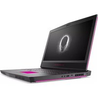
- ALIENWARE®
- AICIENWARE® M17x MOXILE MANUAL
- Notes, Cautions, and Warnings
- CONTENTS
- CHAPTER 1: SETTING UP YOUR LAPTOP ......9
- CHAPTER 2: GETTING TO KNOW YOUR LAPTOP ...... 21
- CHAPTER 3: USING YOUR LAPTOP.... 39
- CHAPTER 4: INSTALLING AND REPLACING COMPONENTS....67
- CHAPTER 5: TROUBLESHOOTING 85
- CHAPTER 6: SYSTEM RECOVERY ...... 99
- CHAPTER 7: SPECIFICATIONS .....103
- APPENDIX 119
- CHAPTER 1:
- SETTING UP YOUR LAPTOP
- CHAPTER 1: SETTING UP YOUR LAPTOP
- Before Setting Up Your Laptop
- Congratulations on the purchase of your Alienware M17x!
- Product Documentation and Media
- Placing Your Laptop
- Connect the AC Adapter
- Press the Power Button
- Connect the Network Cable (Optional)
- Set Up Microsoft Windows
- Set Up WirelessHD (Optional)
- Set Up Wireless Display (Optional)
- Connect to the Internet (Optional)
- Setting Up a Wired Connection
- Setting Up a Wireless Connection
- Setting Up Your Internet Connection
- CHAPTER 2: GETTING TO KNOW YOUR LAPTOP
- Left View Features
- Right View Features
- Back View Features
- Display Features
- Status Lights
- Scroll Lock Light
- Caps Lock Light
- Number Lock Light
- Media Control Keys
- Power Button
- On AC adapter:
- On battery:
- Function Keys
- FI – Suspend Mode
- F2 — Check Battery Status
- F3 – Mute on/off
- F4 – Increase Display Brightness
- F5 – Decrease Display Brightness
- F6 – Display Mode
- F7 – Switchable Graphics Toggle
- F8 – External HDMI Input Toggle
- F9 – Camera on/off
- F10 – Microsoft Mobility Center on/off
- F11 – AlienFX on/off
- F12 – Touch Pad on/off
- CHAPTER 3: USING YOUR LAPTOP
- Alienware Command Center
- Connecting External Displays
- Connecting a Display
- Extending the Desktop
- Using Removable Media and Cards
- CAUTION: Inserting a blank card upside down may damage your laptop.
- Using the Optical Drive
- Using the Integrated Camera
- FastAccess Facial Recognition
- Turning the Camera On and Off
- Using the Wireless Control
- Battery Pack
- Power Management
- Understanding Power Consumption
- Customizing Your Power Settings
- Reducing Power Consumption
- nVidia Optimus Technology (Optional)
- Changing the Application Profile Settings
- Free Fall Sensor
- Configuring the BIOS
- System Setup
- Entering System Setup
- System Setup Screens
- System Setup Options
- Boot Menu
- CHAPTER 4: INSTALLING AND REPLACING COMPONENTS
- Before You Begin
- Turning Off Your Computer
- Before Working Inside Your Computer
- Replacing the Battery Pack
- Upgrading or Replacing Memory
- Removing the Memory Module(s)
- screws (2) 2 compartment door
- Upgrading or Replacing the Hard Drive(s)
- Removing the Hard Drive(s)
- hard drive 2 interposer
- CHAPTER 5: TROUBLESHOOTING
- Basic Hints and Tips
- Backup and General Maintenance
- When troubleshooting your computer, remember the following safety guidelines:
- Things to check:
- Software Diagnostic Tools Pre-Boot System Assessment (PSA)/Enhanced Pre-Boot System Assessment (ePSA)
- Answers to Common Problems
- System
- The computer fails the POST
- The computer stops responding or a solid blue screen appears
- A program stops responding or crashes repeatedly
- End the program:
- A program is designed for an earlier version of Microsoft Windows
- Run the Program Compatibility Wizard:
- Other software problems
- Hard Drive Problems
- Allow the computer to cool before turning it on
- Run Check Disk
- Memory
- Memory errors detected on startup
- Display
- If the display is blank
- Switch the video image:
- Power
- When you press the power button, the computer does not turn on
- AlienRespawn
- AlienRespawn Basic
- Upgrading to AlienRespawn Professional
- CHAPTER 6: SYSTEM RECOVERY
- Dell DataSafe Online Backup (Optional)
- My Dell Downloads
- CHAPTER 7: SPECIFICATIONS
- Computer Model
- Dimensions
- Processor and System Chipset
- Ports and Connectors
- Communications
- Video
- Audio
- Hard-Drive Storage
- Media Card Reader
- Keyboard (Backlit)
- Touch Pad
- Camera
- Battery
- AC Adapter
- Computer Environment
- APPENDIX
- GENERAL AND ELECTRICAL SAFETY PRECAUTIONS
- Computer Setup
- Computer Use
- Electrostatic Discharge (ESD) Warning
- General Safety Precautions
- When You Should Contact Alienware
- Replacement Components or Accessories
- CONTACTING ALIENWARE
- Websites
- Information for NOM, or Official Mexican Standard (Only for Mexico)
Brand : ALIENWARE
Model : M17x R3
Category : Laptop