LK7750 - Bike BH FITNESS - Free user manual and instructions
Find the device manual for free LK7750 BH FITNESS in PDF.


User questions about LK7750 BH FITNESS
0 question about this device. Answer the ones you know or ask your own.
Ask a new question about this device
Download the instructions for your Bike in PDF format for free! Find your manual LK7750 - BH FITNESS and take your electronic device back in hand. On this page are published all the documents necessary for the use of your device. LK7750 by BH FITNESS.
USER MANUAL LK7750 BH FITNESS
natural_image
Line drawing of a stationary exercise machine with monitor and seat (no text or symbols)Instrucciones de montaje y utilización Instructions for assembly and use Instructions de montage et utilisation Montage und gebrauchsanleitung Instruções de montagem e utilização Istruzioni di montaggio e uso Montage-en gebruiksinstrukties
Fig.1
text_image
1 71 59 60 73 56 55 57 53 92 58 93 74 37 97 95 91 63 38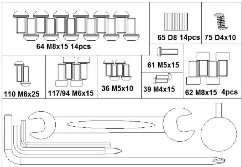
text_image
64 M8x15 14pcs 65 D8 14pcs 75 D4x10 110 M6x25 117/94 M6x15 36 M5x10 61 M5x15 39 M4x15 62 M8x15 4pcsFig.2 F
text_image
1 64 65 71ig.3
text_image
64 65 73Fig.4 Fig.5
text_image
53L 53R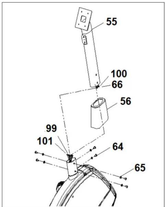
text_image
55 100 66 56 99 101 64 65Fig.6 F
text_image
58 29 57 55 59 62 61 63 110 60ig.6A
text_image
37 38Fig.6B Fig.7
text_image
127 128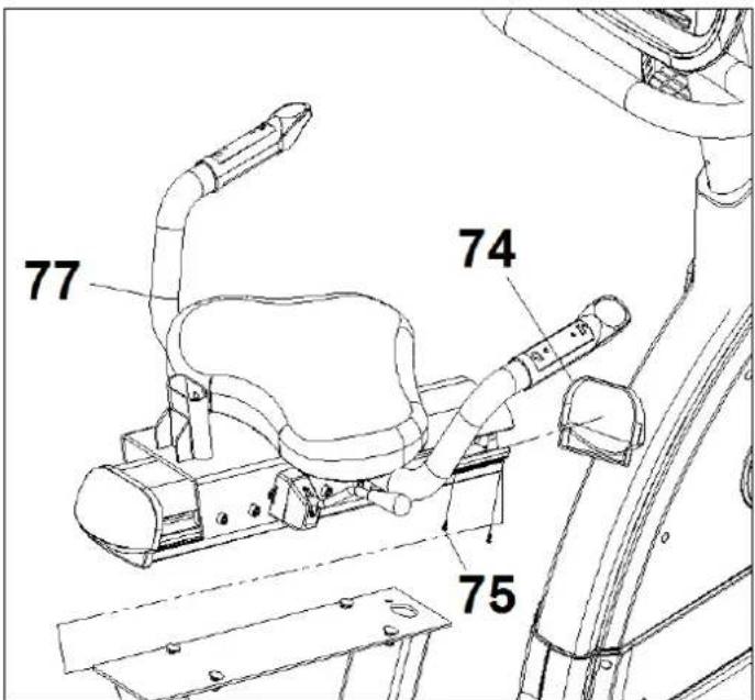
text_image
77 74 75Fig 7A
text_image
1 77 1 77 84 74Fig.8 F
text_image
117 91 94 95 39 92ig.8A
text_image
92 62 93Fig.9 Fig.9A
text_image
67 70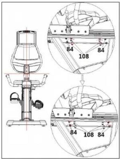
text_image
Technical diagram of a mechanical device with labeled components and cross-sectional viewsFig.10 Fig.11
natural_image
Technical line drawing of a mechanical exercise machine with labeled component '112' (no text or symbols beyond label)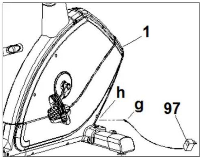
text_image
1 h g 97Español
AVISO IMPORTANTE DE SEGURIDAD PRECAUCIONES
This bicycle has been designed and constructed to provide maximum safety. Nevertheless, certain precautions should be taken when using exercise equipment. Read the whole manual before assembling and using the bicycle. The following safety precautions should also be observed:
1 Keep children away from this equipment at all times. DO NOT leave them unsupervised in the room where this bicycle is kept.
2 It can only be used by one person at a time.
3 If you experience dizziness, nausea, chest pains or any other symptom while using this appliance STOP the exercise. SEEK MEDICAL ATTENTION IMMEDIATELY
4 Use the appliance on a level, solid surface. DO NOT use the bicycle outdoors or close to water.
5 Keep your hands well away from any of the moving parts.
6 Wear clothing suitable for doing exercise. Do not use baggy clothing that might get caught up in the bicycle. Always wear running shoes or trainers when using the machine. Make sure all laces/cords are tied correctly.
7 This appliance must only be used for the purposes described in this manual. DO NOT use accessories that are not recommended by the manufacturer.
8 Do not place sharp objects near the machine.
9 Disabled people should not use the machine without the assistance of a qualified person or a doctor.
10 Do warm up stretching exercises before using the equipment.
11 Do not use the bicycle if it is not working correctly.
Caution: Consult your doctor before beginning to use the bicycle. This advice is especially important for those over 35 or suffering from health problems.
Keep these instructions safe for future use.
GENERAL INSTRUCTIONS
Carefully read through the instructions contained in this manual. It provides you with important information about assembly, safety and use of the machine.
1 This unit has been designed for home use. The weight of the user must not exceed 180 kg.
2 Parents and/or those responsible for children should always take their curious nature into account and how this can often lead to hazardous situations and behaviour resulting in accidents. Under no circumstances should this appliance be used as a toy.
3 The owner is responsible for ensuring that anyone who uses the machine is duly informed about the necessary precautions.
ASSEMBLY INSTRUCTIONS
For the assembly of this unit, we recommend the help of a second person.
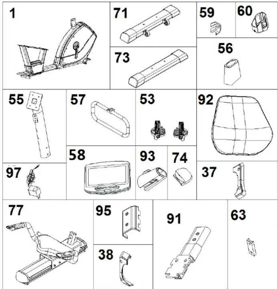
Take the unit out of its box and make sure that all of the pieces are there (Fig. 1)
1.(1) Main body; (53) Right pedal marked with letter (R); (53) Left pedal marked with letter (L), (55) Main post, (56) Post bottom cover, (57) Handlebar; (58) Monitor; (59) Handlebar cover, (60) bottle holder, (71) Front stabiliser bar; (73) Rear stabiliser bar; (74) Rear trim, (77) Rail, (91) Backrest support, (92) Saddle back; (93) (95) Backrest trim; (37) Console trim; (97) Adapter.
Hardware pack containing: (65) Plain washer M8; (61) Slot head bolts M5x15; (110) Slot head bolts M6x25; (38) Slot head bolts M5x10; (39) Slot head bolts M4x15; (62) Slot head bolts M8x15; (64) Slot head bolts M8x15; (75) Slot head bolts M4x10; (94) Slot head bolts M6x15; Allen screw M6; Allen key M5; Double ended ring spanner; Pedal spanner.
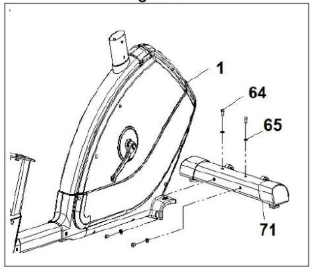
2 Take the front stabiliser bar with wheels (71) and position it as shown in Fig (71), insert bolts (64), fit the plain washers (65), and tighten securely.
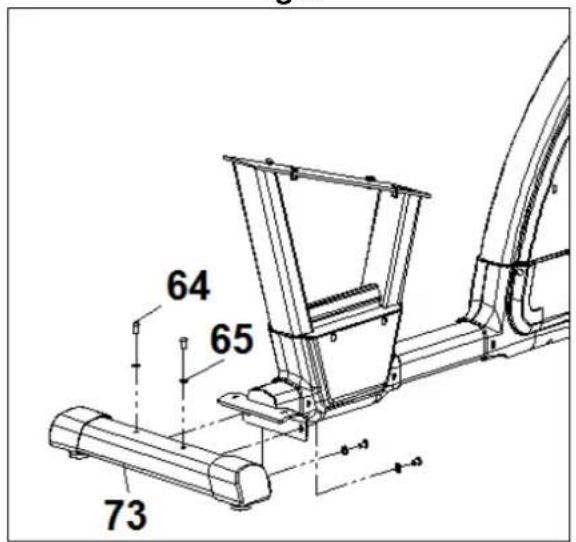
Take the rear stabiliser bar (73) and position it on the machine's rear stand bracket support (1), as shown in (Fig. 3), inserts bolts (64), fit the plain washers (65) and tighten securely.
3 FITTING THE PEDALS
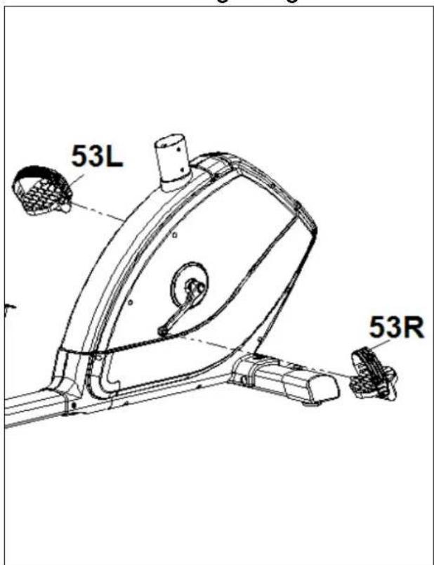
The assembly instructions for the pedals must be followed to the letter, fitting these incorrectly could damage the screw thread on either the pedal or the crank.
Right and left refer to the position that the user adopts when sitting on the saddle to do the exercises.
The right-hand pedal (53), marked with the letter (R), screws onto the right-hand crank, also marked with an (R), in a clockwise direction. Tighten securely, (Fig. 4).
The left-hand pedal (53), marked with the letter (L), screws onto the left-hand crank, also marked with an (L), in an anti-clockwise direction. Tighten securely, (fig 4).
Once the pedals have been fitted, insert the end of the pedal clip into the slot on the pedal adjusting it to your footwear on the ledge of the pedal.
4. FITTING THE MAIN POST.-
Take the main post (55) and insert the bottom post cover (56). Bring the main post (55) up to boss on the main body (1), connect the terminals (99) (66) (100) and (101), Fig.5.
Slip the main post (56) over the boss on the main body (1), Fig.5, making sure not to snag any of the cables.
Refit the screws (64), and the washers (65), Fig.5, and tighten securely.
Lower the bottom trim section (56) for the main post (55) down over the boss section of the main body (1).
5. FITTING THE HANDLEBAR.-
Bring the handlebar (57) up to the handlebar stem (55).
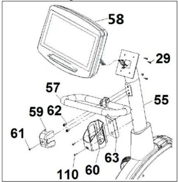
Refit the screws (62), Fig.6, and tighten securely, then fit the bracket cover (59) and screw with screw (61).
6. BOTTLE HOLDER ASSEMBLY.-
Place the bottle holder (60) with the support (63) in the tube (55), and screw with screws (110) Fig.6.
7. FITTING THE MONITOR.-
Place the monitor (58) on top of the plate on the main post (55), as shown in Fig.6, making sure not to pinch the wires.
Use supplied screws (29) to hold the monitor in place, Fig.6.
Next, connect terminals, sticking out of the handlebar post (55), and terminals, sticking out of the monitor (58), Fig.6.
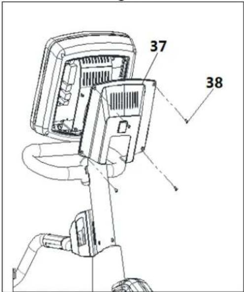
Take the (37) covers and position them on the main post (55), Fig.6A. Now use the screws (38) to attach them to the post.
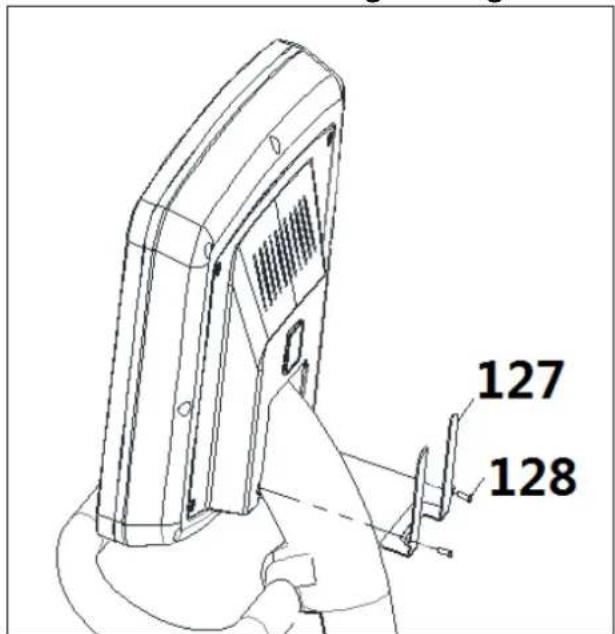
Take the (127) covers and position them on the monitor (58), Fig.6B. Now use the screws (128) to attach them to the post.
8. FITTING THE SADDLE PROFILE
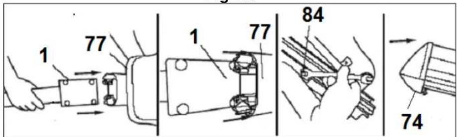
Firstly (Fig 7), place the saddle profile (77) close to the main body (1) and connect terminal from saddle profile. Afterwards introduce tube of main body in aluminium profile, paying special attention to the cables.
Insert the head of the screws in the slots of the rail and tighten the nuts.
Fit the trim (74). Finally, place screw (75) and tighten securely.
9. ATTACHING THE SADDLE
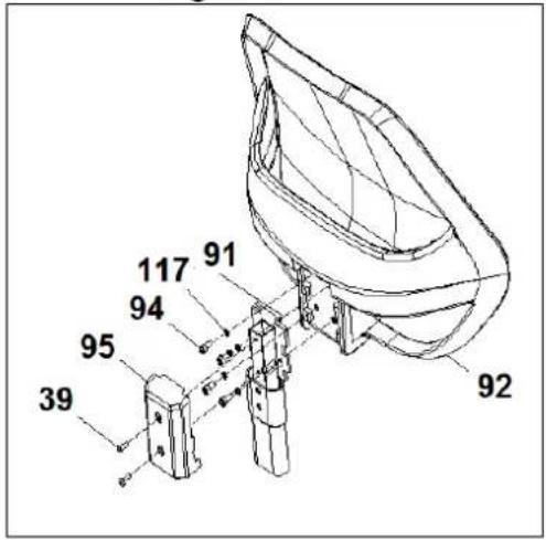
Place saddle back as shown in Fig 8 and screw with screws (94) securely.
Take the back cover (95), position them on the tube (91). Then screw it with the screws (39).
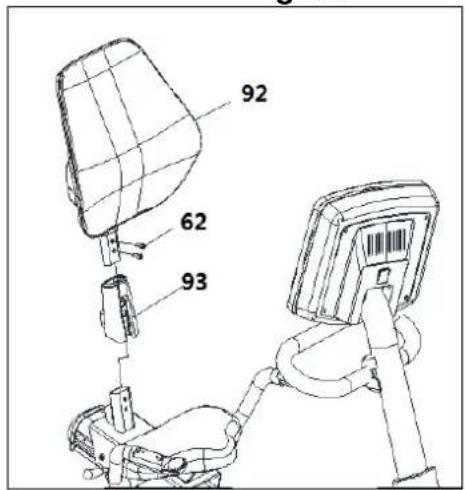
Take the saddle back support tube (91) and insert the cover (93). Slip the saddle back support tube (91) over the boss on the body (77), Fig.8A.
Refit the screws (62), and tighten securely.
Lower the bottom trim section (93) down over the boss section of the body (77).
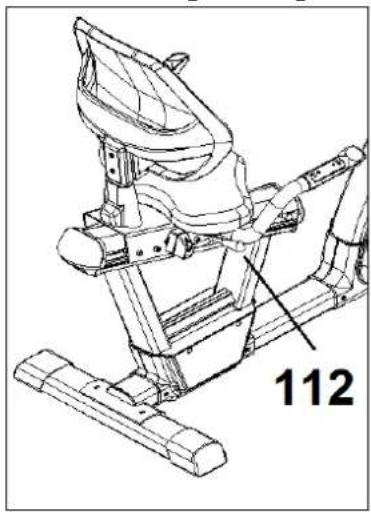
To adjust the seat position, pull the lever (112).
Position in the rail and release the lever again.
10. LEVELLING.
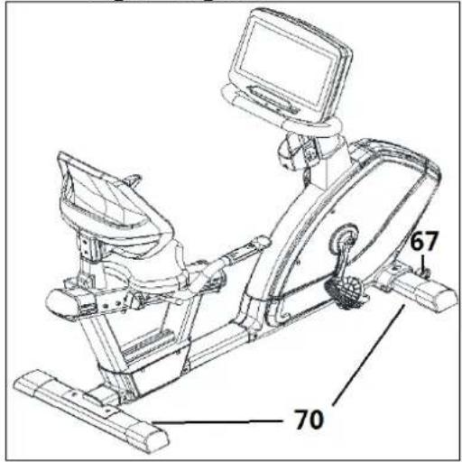
Once the unit has been placed into its final position, make sure that it sits flat on the floor and that it is level. This can be achieved by screwing the adjustable feet (70) up or down, as shown in (Fig 9).
To level the seat:
Loosen the screws (84) under the rail. Level seating position with the screws (108). Tighten the screws (84) again fig.9A.
11. MOVEMENT & STORAGE
The unit is equipped with wheels (67) to make it easier to move. The wheels located at the front of your unit make it easier to move it into a chosen position, by lifting the rear of the unit up slightly and pushing it, as shown in (Fig 9). Store your unit in a dry place, preferably not subject to changes in temperature.
12. MAINS CONNECTION
Insert the jack (g) on the transformer (97) into the connection hole (h) on the main body (1) (bottom, rear of the machine) and then plug the transformer into a 230 V mains supply, (Fig 11).
Do not hesitate to get touch with the Technical Assistance Service if you have any queries by phoning customer services (see last page in manual)
BH RESERVES THE RIGHT TO MODIFY THE SPECIFICATIONS OF ITS PRODUCTS WITHOUT PRIOR NOTICE
Français
IMPORTANTES CONSIGNES DE SÉCURITÉ
PRÉCAUTIONS
text_image
Technical schematic diagram of a mechanical device with numbered components and exploded view, including labeled parts and assembly details.To order replacement parts: Corresponding parts n° Quantity ____
text_image
Exploded view diagram of a device with numbered parts, including control panel, display case, and internal components.| No | Code | No | Code | ||
| 0 | 0 | 90418 | 12 0 | 90430 | |
| 1 | 0 | 90419 | 13 0 | 90431 | |
| 2 | 0 | 90420 | 14 0 | 90460 | |
| 3 | 0 | 90421 | 17 0 | 90434 | |
| 9 | 0 | 90427 | 19 0 | 90436 |
SK2000T
text_image
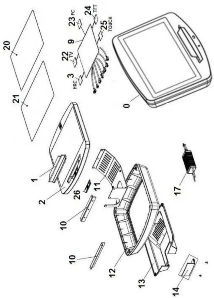
Exploded view diagram of a device with numbered parts and labeled components such as HRC, TV, touch, and touch.| No | Code | No | Code | ||
| 0 | 0 | 190438 | 17 0 | 190447 | |
| 1 | 0 | 190419 | 20 0 | 190448 | |
| 2 | 0 | 190439 | 21 0 | 190449 | |
| 3 | 0 | 190440 | 22 0 | 190450 | |
| 9 | 0 | 190446 | 23 0 | 190451 | |
| 12 | 0 | 190430 | 24 0 | 190452 | |
| 13 | 0 | 190431 | 25 0 | 190453 | |
| 14 | 0 | 190460 | 26 0 | 190454 |
CE
| Español | Por medio de la presente Exercycle S.L. declara que este producto cumple con los requisitos esenciales y cualesquiera otras disposiciones aplicables o exigibles de las Directivas 2009/125/CE, 2011/65/CE, 2004/108/CE y 2006/95/CE. |
| English | Hereby, Exercycle S.L, declares that this product is in compliance with the essential requirements and other relevant provisions of Directives 2005/32/EC, 2011/65/EC, 2004/108/EC and 2006/95/EC. |
| Français | Par la présente Exercycle S.L déclare que cette appareil est conforme aux exigences essentielles et aux autres dispositions pertinentes des directives 2009/125/CE, 2011/65/CE, 2004/108/CE et 2006/95/CE. |
| Deutsch | Hiermit erklärt Exercycle S.L, dass sich das Gerät in Übereinstimmung mit den grundlegenden Anforderungen und den übrigen einschlägigen Bestimmungen der Richtlinien 2009/125/EG, 2011/65/EG, 2004/108/EG und 2006/95/EG befindet. |
| Português | Exercycle S.L. declara que este producto está conforme com os requisitos essenciais e outras disposições das Directivas 2009/125/CE, 2011/65/CE, 2004/108/CE e 2006/95/CE. |
| Italiano | Con la presente Exercycle S.L. dichiara che questo prodotto è conforme ai requisiti essenziali ed alle altre disposizioni pertinenti stabilite delle direttive 2009/125/CE, 2011/65/CE, 2004/108/CE e 2006/95/CE. |
| Nederlands | Hierbij verklaart Exercycle S.L. dat het produkt in overeenstemming is met de essentiële eisen en de andere relevante bepalingen van richtlijnen 2009/125/EG, 2011/65/EG, 2004/108/EG en 2006/95/EG. |
BH HIPOWER SPAIN
EXERCYCLE,S.L. (Manufacturer)
P.O.BOX 195
01080 VITORIA (SPAIN)
Tel.: +34 945 29 02 58
Fax: +34 945 29 00 49
e-mail: hipower@bhfitness.com
www.bhfitness.com
POST-VENTA
Tel: +34 945 292 012 /
902 170 258
Fax: +34 945 56 05 27
e-mail: hipower@bhfitness.com
BH HIPOWER PORTUGAL
MAQUINASPORT, APARELHOS
DE DESPORTO, S.A.
e-mail: info@bhfitness.pt
BH SERVICE PORTUGAL
Tel.: +351 234 729 510
Fax: +351 234 729 519
e-mail: info@bhfitness.pt
BH HIPOWER UK
Tel: 02037347554
e-mail:
sales.uk@bhfitness.com
AFTER SALES – UK
Tel.: 02074425525
e-mail:
service.uk@bhfitness.com
BH NORTH AMERICA
620 N 2nd Street
St. Charles, MO 63301
Tel: + 1 636 487 0050
Toll free: +1 866 325 2339
e-mail:
info@bhnorthamerica.com
www.bhfitnessusa.com
BH HIPOWER ASIA
BH Asia Ltd.
No.80, Jhongshan Rd., Daya Dist.,
Taichung City 42841,
Taiwan. R.O.C.
Tel.: +886 4 25609200
Fax: +886 4 25609280
Block A, NO.68, Branch Lane
455, Lane 822,
Zhen Nan RD., Li Zi Yuan,
Putuo, Shanghai 200331,
P.R.C.
Tel: +86-021-5284 6694
Fax:+86-021-5284 6814
e-mail: info@i-bh.cn
BH HIPOWER FRANCE
SAV FRANCE
Tel : +33 0810 000 301
Fax : +33 0810 000 290
savfrance@bhfitness.com
BH Germany GmbH
Altendorfer Str. 526
45355 Essen
Tel: +49 201 450910-0
e-mail: info@bhgermany.com
SPECIFICATIONS MAY BE CHANGED WITHOUT PRIOR NOTICE DUE TO OUR PROGRAMME OF CONTINUOUS PRODUCT DEVELOPMENT.
BH SE RÉSERVE LE DROIT DE MODIFIER LES SPECIFICATIONS DE SES PRODUITS SANS PRÉAVIS.