EXTNSET4 - Appliance accessory THERMADOR - Free user manual and instructions
Find the device manual for free EXTNSET4 THERMADOR in PDF.

| Features | Details |
|---|---|
| Product Type | Uncategorized |
| Dimensions | Not specified |
| Weight | Not specified |
| Materials | Not specified |
| Usage | Not specified |
| Maintenance | Not specified |
| Safety | Not specified |
| General Information | Not specified |
Frequently Asked Questions - EXTNSET4 THERMADOR
User questions about EXTNSET4 THERMADOR
0 question about this device. Answer the ones you know or ask your own.
Ask a new question about this device
Download the instructions for your Appliance accessory in PDF format for free! Find your manual EXTNSET4 - THERMADOR and take your electronic device back in hand. On this page are published all the documents necessary for the use of your device. EXTNSET4 by THERMADOR.
USER MANUAL EXTNSET4 THERMADOR
For EXTNSET4 Blower Extension Cable Accessory Kit
natural_image
Black-and-white photo of a plated seafood dish featuring whole fish, lemon slices, and garnishes (no text or symbols visible)Safety
DEFINITIONS

WARNING
This indicates that death or serious injuries may occur as a result of non-observance of this warning.

CAUTION
This indicates that minor or moderate injuries may occur as a result of non-observance of this warning.
NOTICE: This indicates that damage to the appliance or property may occur as a result of non-compliance with this advisory.
Note: This alerts you to important information and/or tips.
This THERMADOR ^9 appliance is made by
BSH Home Appliances Corporation
1901 Main Street, Suite 600
Irvine, CA 92614
Questions?
1-800-735-4328
www.thermador.com
We look forward to hearing from you!
Safety

IMPORTANT SAFETY INSTRUCTIONS
READ AND SAVE THESE INSTRUCTIONS
INSTALLER: Please leave these instructions with this unit for the owner. Show the owner the location of the circuit breaker. Mark it for easy reference.
OWNER: Please retain these instructions for future reference.
WARNING
If the information in this manual is not followed exactly, fire or shock may result causing property damage or personal injury.
WARNING
Turn off power circuit at service panel and lock out panel before wiring this appliance. Allow the appliance to cool after the power has been turned off before servicing the appliance.
WARNING
TO REDUCE THE RISK OF FIRE, ELECTRIC SHOCK, OR INJURY TO PERSONS, OBSERVE THE FOLLOWING:
- Use this unit only in the manner intended by the manufacturer.
- Before servicing or cleaning unit, switch power off at service panel and lock the service disconnecting means to prevent power from being switched on accidentally. When the service disconnecting means cannot be locked, securely fasten a prominent warning device, such as a tag, to the service panel.
WARNING
ELECTRICAL SHOCK HAZARD
- DO NOT remove connections.
- DO NOT use an extension cord.
- Improper grounding can result in a risk of electric shock.
- Failure to follow these instructions can result in death, fire, or electrical shock.
This appliance must be grounded. In the event of an electrical short circuit, grounding reduces the risk of electric shock by providing an escape wire for the electric current.
Be sure your appliance is properly installed and grounded by a qualified technician.
If required by the National Electrical Code (or Canadian Electrical Code), this appliance must be installed on a separate branch circuit.
To reduce the risk of fire or electric shock, do not use this appliance with any solid-state speed control devices.
Installation, wire harness routing, electrical connections and grounding must comply with all applicable codes. It is the responsibility of the owner and the installer to determine if additional requirements and/or local or other codes apply to specific installations.
IMPORTANT SAFETY INSTRUCTIONS READ AND SAVE THESE INSTRUCTIONS
CAUTION
For general ventilating use only. DO NOT use to exhaust hazardous or explosive materials and vapors. To reduce the risk of fire, use only metal ductwork.
Proposition 65 Warning
This product may contain a chemical known to the State of California, which can cause cancer or reproductive harm. Therefore, the packaging of your product may bear the following label as required by California:
STATE OF CALIFORNIA PROPOSITION 65 WARNING: ⚠ WARNING
Cancer and Reproductive Harm - www.P65Warnings.ca.gov
The use of multiple extension cables (EXTNCB25W) is NOT supported.
Never modify or alter the construction of the appliance, harness or connectors. Ensure all panels and other components removed during installation are replaced. See blower and hood installation manuals for complete instructions.
CAUTION
Label all wires prior to disconnection when servicing. Wiring errors can cause improper and dangerous operation. Verify proper operation after servicing.
CAUTION
When using the pigtail harness to connect to a hood or blower, be sure to reference the wiring diagram of the hood or blower that is being connected to the pigtail harness. Color-coding of the wiring diagram may not be the same.
WARNING
TO REDUCE THE RISK OF FIRE, ELECTRIC SHOCK, OR INJURY TO PERSONS, OBSERVE THE FOLLOWING:
- Installation work and electrical wiring must be done by qualified person(s) in accordance with all applicable codes and standards, including fire-rated construction.
- Sufficient air is needed for proper combustion and exhausting of gases through the flue (chimney) of fuel burning equipment to prevent back drafting. Follow the heating equipment manufacturer's guideline and safety standards such as those published by the National Fire Protection Association (NFPA), and the American Society for Heating, Refrigeration and Air Conditioning Engineers (ASHRAE), and the local code authorities.
- USE ONLY METAL DUCTWORK.
- Ducted fans must always be vented to the outdoors. Do not vent exhaust air into spaces within walls, ceilings, attics, crawl spaces or garages.
- When cutting or drilling into wall or ceiling, do not damage electrical wiring and other hidden utilities.
Installation instructions
Before you begin
The EXTNSET4 adapter kit is for connections when wiring Thermador blowers to products other than the Thermador Professional Series hoods with the EXTNCB25W 25 ft. extension cable.
IMPORTANT: Cutting off a connector to the appliance or to the extension cable kit will void the warranty.
NOTE: Refer to the hood and the blower manufacturer's installation instructions.
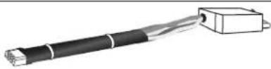
Parts included
- Adapter no. 1 – material no. 9001242198
- Pigtail harness no. 1 – material no. 8001090211
- Pigtail harness no. 2 – material no. 8001090212
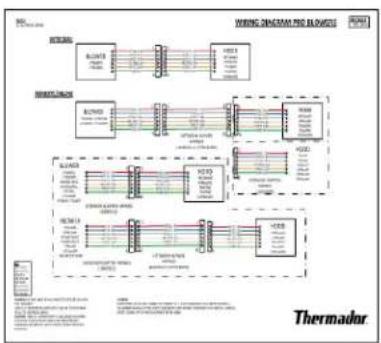
- Wiring diagram
Adapter kit compatibilities
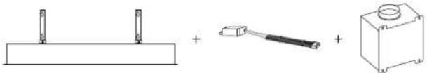
Adapter no. 1
9001242198
SVC. no. 00750108
natural_image
Pure mechanical assembly diagram showing two plates, a tool, and a box with a cylindrical component (no text or symbols)| Hood Blower | ||
| VCI2xxDS VTI610W | VTI1010W | VTR630W |
| VTR1030W | ||
text_image
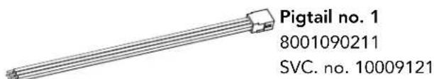
Pigtail no. 1 8001090211 SVC. no. 10009121
natural_image
Diagram showing three components: a triangular prism, a coiled cable with connectors, and a rectangular container (no text or symbols)| Hood | 25 ft. extension cable | Blower | |
| HPCNxxWS | PHxxHWS | EXTNCB25W | Other* |
| HPINxxWS | VCINxxGWS | ||
| PHxxGWS | |||
*Reference the blower wiring diagram for connections.
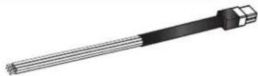
Pigtail no. 2
8001090212
SVC. no. 12025288
natural_image
3D rendering of a cylindrical mechanical component with segmented body and protruding shaft (no text or symbols)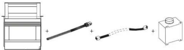
natural_image
Diagram showing three components: a box with a plus sign, a connector with a plus sign, and a battery with a dashed line connection (no text or symbols)| Hood 25 ft. extension | cable Blower | |
| Other* | EXTNCB25W VTI610W | VTI1010WVTR630WVTR1030W |
| HDD80050UC | ||
| HDD86050UC | ||
| UCVM30RS | ||
| UCVM36RS | ||
| UCVP36RS |
*Reference the hood wiring diagram for connections.
Adapter installation
To connect the extension cable and adapter to the hood
- Route the hood harness through the hood's knockout hole. Secure with a 3/4'' (19 mm) strain relief.
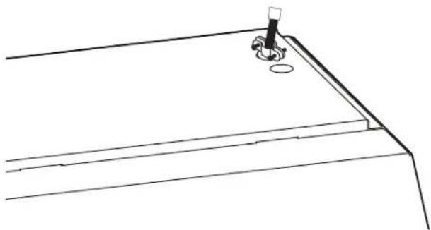
natural_image
Pure technical line drawing of a mechanical component or bracket (no text or symbols)- Follow the wiring diagram for complete instructions.
flowchart
graph TD
    A["Sensor"] --> B["Module 1"]
    A --> C["Module 2"]
    A --> D["Module 3"]
    A --> E["Module 4"]
    A --> F["Module 5"]
    B --> G["Thermometer"]
    C --> G
    D --> G
    E --> G
    F --> G
    G --> H["Thermometer"]
    style A fill:#f9f,stroke:#333
    style B fill:#ccf,stroke:#333
    style C fill:#ccf,stroke:#333
    style D fill:#ccf,stroke:#333
    style E fill:#ccf,stroke:#333
    style F fill:#ccf,stroke:#333
6696 Financial Drive, Unit 3
Mississauga, ON L5N 7J6
Des questions?
1-800-735-4328
www.thermador.ca
natural_image
Line drawing of a mechanical component with a base and mounting bracket (no text or symbols)natural_image
Pure technical line drawing of a mechanical component or bracket (no text or symbols)Thank you for being a Thermador customer!
Thermador is dedicated to supporting you and your appliance so you have many years of creative cooking. Please don't hesitate to contact us if you have any questions. We're happy to help you with cleaning and care instructions, cooking tips, accessories, troubleshooting, and more.
USA:
1-800-735-4328
thermador.com/customer-care
Canada:
1-800-735-4328
thermador.ca/support
Accessories and parts
Filters, Thermador cleaners, teppanyaki pans, griddles, replacement parts, and more can be purchased in our online accessories store.
USA:
store.thermador.com/us
Canada:
Filters, parts and accessories can be purchased through our distributors.
Marcone: 1-800-287-1627
Reliable Parts: 1-800-663-6060
Soutien
thermador.ca/support
thermador.ca/support