LE750 - Leaf blower BLACK & DECKER - Free user manual and instructions
Find the device manual for free LE750 BLACK & DECKER in PDF.

| Product Type | Electric Edger |
| Brand | Black & Decker |
| Model | LE750 |
| Power Source | Electric with Cord |
| Rated Voltage | 120 V |
| Frequency | 60 Hz |
| Cutting Depth | Adjustable, recommended 1 in (2.5 cm) |
| Edge Guide | Adjustable (edging/trenching) |
| Auxiliary Handle | Yes, height adjustable |
| Blade | Steel blade with wear indicators |
| Intended Use | Domestic, edging and landscaping |
| Warranty | 2-year limited (domestic use) |
| Maintenance | Clean with compressed air, do not immerse |
| Safety | Wear safety glasses, use outdoor extension cord |
| Replacement Parts | Replacement blade, nut and conical washer |
Frequently Asked Questions - LE750 BLACK & DECKER
User questions about LE750 BLACK & DECKER
0 question about this device. Answer the ones you know or ask your own.
Ask a new question about this device
Download the instructions for your Leaf blower in PDF format for free! Find your manual LE750 - BLACK & DECKER and take your electronic device back in hand. On this page are published all the documents necessary for the use of your device. LE750 by BLACK & DECKER.
USER MANUAL LE750 BLACK & DECKER
Please read before returning this product for any reason.
English (original instructions) 1
Definitions: Safety Alert Symbols and Words
This instruction manual uses the following safety alert symbols and words to alert you to hazardous situations and your risk of personal injury or property damage.
DANGER: Indicates an imminently hazardous situation which, if not avoided, will result in death or serious injury.
WARNING: Indicates a potentially hazardous situation which, if not avoided, could result in death or serious injury.
CAUTION: Indicates a potentially hazardous situation which, if not avoided, may result in minor or moderate injury. (without word) Indicates a safety related message.
NOTICE: Indicates a practice not related to personal injury which, if not avoided, may result in property damage.
Fig. A
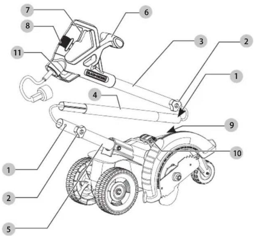
1 Mounting hole
2 Knob
3 Upper tube
4 Middle tube
5 Lower tube
6 Auxiliary handle
7 Trigger switch
8 Main handle
9 Cut depth knob
10 Edge guide lever
11 Extension cord retainer
WARNING: Read all safety warnings
and all instructions. Failure to follow the warnings and instructions may result in electric shock, fire and/or serious injury.

WARNING: To reduce the risk of injury, read the instruction manual.
If you have any questions or comments about this or any product, call BLACK+DECKER toll free at: 1-800-544-6986.
IMPORTANT SAFETY INSTRUCTIONS

To reduce risk of injury:
- Before any use, be sure everyone using this unit reads and understands all safety instructions and other information contained in this manual.
- Save these instructions and review frequently.

When using electric gardening appliances, basic safety precautions should always be followed to reduce risk of fire, electric shock, and personal injury, including the following.
- Avoid Dangerous Environment – Don't use appliances in damp or wet locations.
- Don't Use In Rain.
- Keep Children Away – All visitors should be kept at a distance from work area.
- Dress Properly – Do not wear loose clothing or jewelry. They can be caught in moving parts. Use of rubber gloves and substantial footwear is recommended when working outdoors. Wear protective hair covering to contain long hair.
- Use Safety Glasses – Always use face or dust mask if operation is dusty.
- Use Right Appliance – Do not use appliance for any job except that for which it is intended.
- Ground Fault Circuit Interrupter (GFCI) protection should be provided on the circuit(s) or outlet(s) to be used for the gardening appliance. Receptacles are available having built-in GFCI protection and may be used for this measure of safety.
- Warning – To reduce the risk of electric shock, use only with an extension cord intended for outdoor use, such as an extension cord of cord type SW-A, SOW-A, STW-A, STOW-A, SJW-A, SJOW-A, SJTW-A. or SJTOW-A.
- Extension Cord – Make sure your extension cord is in good condition. When using an extension cord, be sure to use one heavy enough to carry the current your product will draw. An undersized extension cord will cause a drop in line voltage resulting in loss of power and overheating. Minimum Gauge for Cord Sets, shows the correct size to use depending on cord length and nameplate ampere rating. If in doubt, use the next heavier gauge. The smaller the gauge number, the heavier the cord. To reduce the risk of disconnection of appliance cord from the extension cord during operating:
i) Make a knot as shown in Figure B; or
ii) Use one of the plug-receptacle retaining straps or connectors described in this manual.
OR
iii) Secure the extension cord to the appliance plug as shown or described in Assembly and Adjustments.
Fig. B
natural_image
Simple line drawing of a plug with coiled wires (no text or symbols)- Avoid Unintentional Starting – Don't carry plugged-in appliance with finger on switch. Be sure switch is off when plugging in.
- Don't Abuse Cord – Never carry appliance by cord or yank it to disconnect from receptacle. Keep cord from heat, oil, and sharp edges.
- Don't grasp the exposed cutting blades or cutting edges when picking up or holding the appliance.
- Don't Force Appliance – It will do the job better and with less likelihood of a risk of injury at the rate for which it was designed.
- Don't Overreach – Keep proper footing and balance at all times.
- Stay Alert – Watch what you are doing. Use common sense. Do not operate appliance when you are tired.
- Disconnect Appliance – Disconnect the appliance from the power supply when not in use, before servicing, when changing accessories such as blades, and the like.
- Store Idle Appliances Indoors – When not in use, appliances should be stored indoors in dry, and high or locked-up place – out of reach of children.
- Maintain Appliance With Care – Keep cutting edge sharp and clean for best performance and to reduce the risk of injury. Follow instructions for lubricating and changing accessories. Inspect appliance power source periodically, and if damaged, have it repaired by an authorized service facility. Inspect extension cords periodically and replace if damaged. Keep handles dry, clean, and free from oil and grease.
- Check Damaged Parts – Before further use of the appliance, a guard or other part that is damaged should be carefully checked to determine that it will operate properly and perform its intended function. Check for alignment of moving parts, binding of moving parts, breakage of parts, mounting, and any other condition that may affect its operation. A guard or other part that is damaged should be properly repaired or replaced by an authorized service center unless indicated elsewhere in this manual.
SAVE THESE INSTRUCTIONS
Additional Safety Warnings

To reduce the risk of
rebound (ricochet) injury, work going away from any nearby solid object such as wall, steps, large stone, tree, etc.
- GUARD – Do not use this appliance without guard attached.
- BLADE – Keep blade area clean.
- KEEP FACE, HANDS AND FEET CLEAR OF CUTTING AREA AT ALL TIMES. The rotating line performs a cutting function use care when trimming around screens and desirable plantings.
- KEEP ALL BYSTANDERS AWAY – at a safe distance from work area, especially children. MAKE SURE that other persons and pets are at least 100' (30 m) away.
- BEFORE LANDSCAPING OR TRENCHING, check for buried electrical cables.
- USE GREAT CARE when working close to solid objects and where necessary, do trimming by hand.
- DAMAGE TO UNIT – If you strike or become entangled with a foreign object, stop appliance immediately, disconnect cord, check for damage and have any damage repaired before further operation is attempted.
- DO NOT OPERATE portable electric appliances in gaseous or explosive atmospheres. Motors in these appliances normally spark, and the sparks might ignite fumes.
- STAY ALERT – Do not operate this unit when you are tired, ill, or under the influence of alcohol, drugs, or medication.
- DO NOT immerse appliance in water or squirt it with a hose.
- DO NOT allow any liquid to get inside it. If appliance does get wet, allow to dry for a minimum of 48 hours.
• DO NOT clean with a pressure washer. - DO NOT store the appliance on or adjacent to fertilizers or chemicals.
• DO NOT charge appliance in rain, or in wet locations. - REPLACEMENT PARTS: When servicing use only identical replacement parts.
Important Safety Instructions: Polarized Plugs
To reduce the risk of electric shock, this equipment has a polarized plug (one blade is wider than the other). This equipment must be used with a suitable polarized 2 wire or 3 wire extension cord. Polarized connections will fit together only one way. Make sure that the receptacle end of the extension cord has large and small blade slot widths. If the plug does not fit fully into the extension cord, reverse the plug. If it still does not fit, obtain a suitable extension cord. If the extension cord does not fit fully into the outlet, contact a qualified electrician to install the proper outlet. Do not modify the appliance plug or extension cord in any way.
Additional Safety Information

Never modify the power
tool or any part of it. Damage or personal injury could result.

ALWAYS use safety glasses.
Everyday eyeglasses are NOT safety glasses. Also use face or dust mask if operation is dusty. ALWAYS WEAR CERTIFIED SAFETY EQUIPMENT:
• ANSI Z87.1 eye protection (CAN/CSA Z94.3),
• ANSI S12.6 (S3.19) hearing protection,
• NIOSH/OSHA/MSHA respiratory protection.

Some dust contains
chemicals known to State of California to cause cancer, birth defects or other reproductive harm. Some examples of these chemicals are:
• compounds in fertilizers,
• compounds in insecticides, herbicides and pesticides,
• arsenic and chromium from chemically treated lumber.
To reduce your exposure to these chemicals, wear approved safety equipment such as dust masks that are specially designed to filter out microscopic particles.

Use of this tool can generate
and/or disperse dust, which may cause serious and permanent respiratory or other injury. Always use NIOSH/OSHA approved respiratory protection appropriate for the dust exposure. Direct particles away from face and body.

Always wear proper
personal hearing protection that conforms to ANSI S12.6 (S3.19) during use. Under some conditions and duration of use, noise from this product may contribute to hearing loss.

When not in use, place tool
on its side on a stable surface where it will not cause a tripping or falling hazard. Some tools will stand upright but may be easily knocked over.
- Air vents often cover moving parts and should be avoided. Loose clothes, jewelry or long hair can be caught in moving parts.
- An extension cord must have adequate wire size (AWG or American Wire Gauge) for safety. The smaller the gauge number of the wire, the greater the capacity of the cable, that is, 16 gauge has more capacity than 18 gauge. An undersized cord will cause a drop in line voltage
ENGLISH
resulting in loss of power and overheating. When using more than one extension to make up the total length, be sure each individual extension contains at least the minimum wire size. The following table shows the correct size to use depending on cord length and nameplate ampere rating. If in doubt, use the next heavier gauge. The lower the gauge number, the heavier the cord.
Minimum Gauge for Cord Sets
| Volts | Total Length of Cord in Feet (meters) | ||||
| 120 V 25 (7.6) | 50 (15.2) 100 (30.5) 150 (45.7) | ||||
| 240 V 50 (15.2) | 100 (30.5) 200 (61.0) 300 (91.4) | ||||
| Ampere Rating | American Wire Gauge | ||||
| More Than | Not More Than | ||||
| 0618 | 161614 | ||||
| 61018 | 161412 | ||||
| 1012 | 16161412 | ||||
| 1216 | 1412 Not Recommended | ||||
The label on your tool may include the following symbols. The symbols and their definitions are as follows:
V....volts
Hz......hertz
min......minutes
=--- or DC.....direct current
Class I Construction (grounded)
.../min.....per minute
BPM.....beats per minute
⚠️......safety alert symbol
▲......visible radiation
...... avoid staring at light
......wearrespiratory protection
weareye protection
O....wearhearing
protection
readall documentation
IPXX......IPsymbol
Intended Use
This edger is intended for household use.
DO NOT use under wet conditions or in presence of flammable liquids or gases.
DO NOT let children come into contact with the tool. Supervision is required when inexperienced operators use this tool.
Motor
Be sure your power supply agrees with the nameplate marking. Voltage decrease of more than 10% will cause loss of power and overheating. These tools are factory tested; if this tool does not operate, check power supply.
ASSEMBLY AND ADJUSTMENTS
WARNING: To reduce the risk of serious personal injury, turn unit off and disconnect it from power source before making any adjustments or removing/installing attachments or accessories. An accidental start-up can cause injury.
DANGER: UNPLUG TOOL. Wait for blade to
come to complete stop.
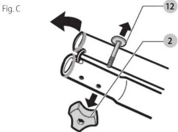
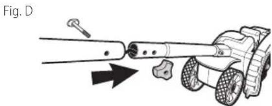
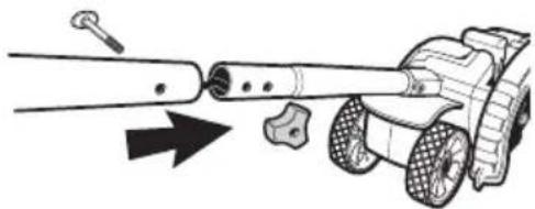
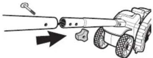
Assembling the Handle Tubes
(Fig. A, C, D, G)
-
Remove knobs 2 and curved head bolts 12 from handle tube mounting holes.
-
Remove tape which secures internal jacketed cable to tubes.
-
Slide middle tube 4 into upper tube 3 and fasten handle tubes together with the knob and curved head bolt. Note that when you first insert the bolt it may be necessary to wiggle it carefully to get it past the jacketed cable inside the tube. There are two positions available for adjustment to your preferred height setting. See Figure A, F for upper handle orientation. Ensure the cable moves smoothly into the handle tubes while assembling.
-
Push jacketed cable down into lower tube to remove the slack. Slide the middle tube into the lower by locating the groove and the bump. Fasten handle tubes together with the remaining knob and curved head bolt. Note that when you first insert the bolt it may be necessary to wiggle it carefully to get it past the jacketed wire inside the tube.
CAUTION: NEVER use a sharp object to move jacketed wires out of the way.
natural_image
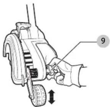
Diagram of a mechanical device with a tool and arrow indicating motion (no text or symbols)Cut Depth Adjustment (Fig. A, E)
The front wheel can be adjusted to allow a deeper or shallower cut, and to increase the life of the blade.
- Wait for blade to come to complete stop.
- Unplug tool.
- Loosen the cut depth knob 9.
- Adjust wheel depth, using the depth indicator (on the wheel bracket and the marking on the front housing. nOTE: Recommend 1" (25 mm) depth for edging.
- Tighten knob firmly.
NOTE: Thick overgrowth may drag on the guard. Reduce cut depth to minimum to help reduce this effect.
Fig. E
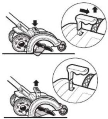
Pull-Up Edge Guide (Fig. A, F)
The edge guide is useful for cutting a straight path along sidewalks. For landscaping or trenching in the yard the edge guide can interfere with moving the edger through hard soil or sod. The edge guide can be adjusted so that the tool will also perform TRENCHING and LANDSCAPING operations.
To Change Position of the Edge Guide (Fig. F, G)
Landscaping
Pull edge guide lever 10 sideways to unlock from the guard tab in direction of small arrow. Lift the lever up until the lower square notch in the lever lines up with the tab on the guard. In this position the edge guide is lifted up so the tool can easily cut along the edges of flower and shrubbery beds, and around trees in preparation for trenching or sod removal.
Trenching
To return edge guide to lower position, pull lever sideways and push down until guard tab fits into upper lever hole.
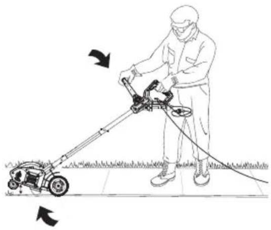
NOTE: You may need to tilt edger back to allow edge guide to be moved into trenching position as shown in Fig. G.
Fig. F
natural_image
Illustration of a roller roller mechanism with two views showing different states of motion (no text or symbols present)Fig. G
natural_image
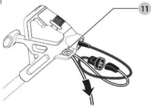
Illustration of a person using a lawn power curling machine to clean grass (no text or symbols)Attaching Extension Cord To Edger (Fig. H)
An extension cord retainer 11 is built into the switch handle to reduce strain on the power cord. To use this feature, simply double the extension cord as shown, about 1' (30 cm) from the end, and insert it into the end of the handle. Hook the loop formed by doubling the cord over the tab. Gently tug on the cord to ensure that it is firmly retained in the handle.
Keep extension cord clear of operator, unit, and any obstacles at all times. Do not expose the cord to heat, oil, water, or sharp edges.
Fig. H
natural_image
Technical line drawing of a mechanical clamp or connector with wires and connectors (no text or symbols)English
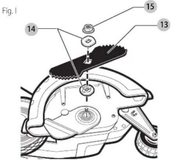
Blade (Fig. I)
ANGER: Unplug tool. Wait for blade to come to complete stop.
The blade 13, two spacers 14 and hex head nut 15 with conical washer should be attached to your edger in the order shown. Please check that the blade has been properly mounted before using your edger. The edger blade has two wear indicators that show when blade needs to be replaced. When the blade wears to the small hole at each end of the blade it will give only 1/4" (6 mm) depth of cut and should be replaced.
NOTE: To increase blade life, keep initial cutting depth at minimum and increase depth setting as blade wears.
Blade Replacement
ANGER: Unplug tool. Wait for blade to come to complete stop.
ANGER: Blade rotates momentarily after the switch is released.
- Loosen the hex head nut 15 (9/16"). Use a 1" wrench on the outer spacer 14, or a 2"x4" wood block between the blade 13 and guard if necessary to hold the blade from turning.
- Ensure inner spacer is on shaft—"flats" in spacer hole must engage with "flats" on shaft.
- Holding the spacer in place, put the blade on the shaft, as shown (Figure I).
- Hold the blade against the spacer and install the outer spacer, again aligning the flats in the spacer with the flats on the shaft.
- Install the hex head nut and conical washer, then tighten with a wrench. nOTE: Replace hex head nut and conical washer only with identical replacement part.
OPERATION
WARNING: To reduce the risk of serious personal injury, turn unit off and disconnect it from power source before making any adjustments or removing/installing attachments or accessories. An accidental start-up can cause injury.
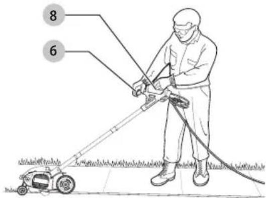
Proper Hand Position (Fig. J)
WARNING: To reduce the risk of serious personal injury, ALWAYS use proper hand position as shown.
WARNING: To reduce the risk of serious personal injury, ALWAYS hold securely in anticipation of a sudden reaction.
Proper hand position requires one hand on the main handle 8 and one hand on the auxiliary handle 6.
Fig. J
Switch (Fig. A)
To turn tool ON, squeeze the trigger switch 7. The trigger has been designed so that it is very easy to hold in the ON position. To turn tool OFF, release the trigger.
NOTE: The edger is a major appliance and should not be operated simultaneously with other major appliances on the same household circuit.
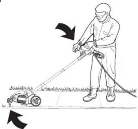
Usage
- Set cut depth at 1" and set edge guide to the down position, refer to Assembly and Adjustments Instructions.
- Before starting the edger, line up the tool so the edge guide rests against the edge of the paved surface. Both rear wheels should be on the paved surface when edging.
NOTE: When there is heavy overgrowth of grass over the paved surface it may drag on the guard. An initial cut may be required with the edger on the grass side. This will require lifting up the edge guide and may require reducing the depth of cut (refer to To Change Position of the Edge Guide instructions).
- To avoid kickback of edger, tilt the handle down so the blade is above the ground.
- Turn switch ON and allow blade to spin without moving tool.
- Slowly lift the handle to lower the blade, finding the edge of the paved surface and start edging. Then move tool forward slowly along edge of paved surface, keeping the edge guide pressed lightly against the pavement edge.
- For the first edging each season, it is best to move forward slowly because grass is thickest then. Subsequent edging will be completed more rapidly. If the tool slows down, back it up an inch or two until the blade comes up to normal speed. During edging some sparks may be generated from hitting stones. This is normal. Do not attempt to edge when the grass or soil is wet or moist—for electrical safety and to prevent clogging of the blade chamber. If you must edge under conditions that cause the blade chamber to become clogged, release trigger, wait for blade to come to complete stop. Unplug tool, open door and remove clogged material with a stick. To continue to operate the tool in a clogged condition will seriously overload the motor.
CAUTION:
Do not attempt to unclog the
blade chamber by dropping or tapping the tool on the ground. This can damage the unit. Keep hands clear of edge guide and blade when cleaning as these wear to a very sharp point during edging.
Landscaping/Trenching
WARNING:
Before Landscaping or
Trenching, inspect and ensure there are no exposed or buried cables, pipes or other objects that may create a hazard or interfere with operating the edger. Set depth to only that required for the job. Do not overload. If tool slows, pull back slightly and wait until blade comes up to normal speed.
Storage
WARNING:
Be sure the tool is unplugged.
Remove and clean any debris from the outside of the edger and inside of guard before storage. Refer to MAINTENANCE section. If necessary, the edger may be stored by hanging on a hook by its handle.
AUTION:
Do not hang edger on the
switch trigger or power cord.
NOTICE:
Do not store the tool on or adjacent to fertilizers or chemicals. Such storage can cause rapid corrosion.
Preventing Corrosion
Fertilizers and other garden chemicals contain agents that greatly accelerate the corrosion of metals. If you use the tool in areas where fertilizers or chemicals have been used, the tool should be cleaned immediately afterwards. Wipe all exposed parts with a damp cloth. You may lubricate only metal parts with a light petroleum based oil.
When cleaning, DO NOT immerse tool in water or squirt it with a hose.
MAINTENANCE
WARNING:
To reduce the risk of
serious personal injury, turn unit off and disconnect it from power source before making any adjustments or removing/installing
attachments or accessories. An accidental start-up can cause injury.
Cleaning
WARNING:
Blow dirt and dust out of all air vents with clean, dry air at least once a week. To minimize the risk of eye injury, always wear ANSI Z87.1 approved eye protection when performing this procedure.
WARNING:
Never use solvents or other harsh chemicals for cleaning the non-metallic parts of the tool. These chemicals may weaken the plastic materials used in these parts. Use a cloth dampened only with water and mild soap. Never let any liquid get inside the tool; never immerse any part of the tool into a liquid.
Accessories
WARNING:
Since accessories, other than those offered by BLACK+DECKER, have not been tested with this product, use of such accessories with this tool could be hazardous. To reduce the risk of injury, only BLACK+DECKER recommended accessories should be used with this product.
Recommended accessories for use with your tool are available at extra cost from your local dealer or authorized service center. If you need assistance in locating any accessory, please contact BLACK+DECKER call 1-800-544-6986.
Repairs
WARNING:
To assure product SAFETY and RELIABILITY, repairs, maintenance and adjustment (including power cord repairs, and brush inspection and replacement, when applicable) should be performed by a BLACK+DECKER factory service center or a BLACK+DECKER authorized service center. Always use identical replacement parts.
Register Online
Thank you for your purchase. Register your product now for:
- WARRANTY sERViCE: Registering your product will help you obtain more efficient warranty service in case there is a problem with your product.
- COnFiRMATiOn OF OWnERshiP: In case of an insurance loss, such as fire, flood or theft, your registration of ownership will serve as your proof of purchase.
- FOR YOUR SAFETY: Registering your product will allow us to contact you in the unlikely event a safety notification is required under the Federal Consumer Safety Act.
- Register online at www.BlackandDecker.com/NewOwner
TWO-YEAR LIMITED WARRANTY
Black & Decker (U.S.) Inc. warranties this product to be free from defects in material or workmanship for a period of two (2) years following the date of purchase, provided that the product is used in a home environment. This limited warranty does not cover failures due to abuse, accidental damage or when repairs have been made or attempted by anyone other than BLACK+DECKER and its Authorized Service Centers. A defective product meeting the warranty conditions set forth herein will be replaced or repaired at no charge in either of two ways:
The first, which will result in exchanges only, is to return the product to the retailer from whom it was purchased (provided that the store is a participating retailer). Returns should be made within the time period of the retailer's policy for exchanges. Proof of purchase may be required. Please check with the retailer for its specific return policy regarding time limits for returns or exchanges. The second option is to take or send the product (prepaid) to a BLACK+DECKER owned or authorized Service Center for repair or replacement at BLACK+DECKER's option. Proof of purchase may be required. BLACK+DECKER owned and authorized service centers are listed online at www.blackanddecker.com. This warranty does not apply to accessories. This warranty gives you specific legal rights and you may have other rights which vary from state to state or province to province. Should you have any questions, contact the manager of your nearest BLACK+DECKER Service Center. This product is not intended for commercial use, and accordingly, such commercial use of this product will void this warranty. All other guarantees, express or implied, are hereby disclaimed.
LATIN AMERICA: This warranty does not apply to products sold in Latin America. For products sold in Latin America, check country specific warranty information contained in the packaging, call the local company or see the website for such information.
natural_image
Simple line drawing of a plug with coiled wires (no text or symbols)fabrication classe II (double isolation)
○ protection auditive
Fig. D
natural_image
Diagram of a mechanical device with a tool and wheels, showing an arrow indicating motion (no text or symbols present)natural_image
Line drawing of a hand operating a lawn mower with a tire, showing mechanical components and motion direction (no text or symbols)Guide de rebord (Fig. A, F)
natural_image
Illustration of a roller roller mechanism with two views showing different states of motion (no text or symbols present)FRAnÇAis
Fig. G

natural_image
Line drawing of a person using a lawn power curling machine on a grassy field (no text or symbols)natural_image
Technical diagram of a cable connector with wires and connectors, no text or symbols presentLame (Fig. I)
Importé par.Black & Decker (U.S.) Inc.,
701 E. Joppa Rd.
Towson, MD 21286

BlackandDecker.com
(1-800-544-6986)
natural_image
Simple line drawing of a plug with coiled wires (no text or symbols)Fig. D
natural_image
Diagram of a mechanical device with a tool and arrow indicating motion (no text or symbols)Guía para bordes plegable (Fig. A, F)
natural_image
Illustration of a mechanical device with two views showing internal components and directional arrows (no text or symbols)Fig. G
natural_image
Line drawing of a person using a lawn power curler to clean grass, with arrows indicating direction of motion (no text or symbols)natural_image
Diagram of a handheld electric shock absorber with wires and connectors, no text or symbols presentCuchilla (Fig. I)
Eje Central Lázaro Cárdenas No. 18 - Local (55) 5588 9377 D, Col. Obrera
MERIDA, YUC
Calle 63 #459-A - Col. Centro (999) 928 5038
MONTERREY, N.L.
Av. Francisco I. Madero 831 Poniente - Col. (818) 375 23 13 Centro
PUEBLA, PUE
17 Norte #205 - Col. Centro (222) 246 3714
QUERETARO, QRO
Av. San Roque 274 - Col. San Gregorio (442) 2 17 63 14
SAN LUIS POTOSI, SLP
Imported by. Black & Decker (U.S.) Inc.,
701 E. Joppa Rd.
Towson, MD 21286

BlackandDecker.com
(1-800-544-6986)