T14038 - Sanitary faucets DELTA - Free user manual and instructions
Find the device manual for free T14038 DELTA in PDF.
| Features | Details |
|---|---|
| Product type | Uncategorized |
| Usage | Information not available |
| Maintenance | Information not available |
| Safety | Information not available |
| General information | Information not available |
Frequently Asked Questions - T14038 DELTA
User questions about T14038 DELTA
0 question about this device. Answer the ones you know or ask your own.
Ask a new question about this device
Download the instructions for your Sanitary faucets in PDF format for free! Find your manual T14038 - DELTA and take your electronic device back in hand. On this page are published all the documents necessary for the use of your device. T14038 by DELTA.
USER MANUAL T14038 DELTA
To reduce the risk of injury due to hot water burns, make sure the enclosed labels are applied where specified on the label.
DOCUMENTOS IMPORTANTES INCLUIDOS AVISO:
NOTICE TO INSTALLER: Place this label on the water heater next to the temperature adjustment knob. WARNING:
These series of tub/shower valves do not adjust automatically for changes in temperature at the hot water heater or inlet. If the temperature setting of the hot water heater or inlet is changed, the setting on these valves must be adjusted manually! Failure to re-adjust the valve may result in hot water burns or extreme cold resulting from variations in line pressure (such as when a dishwasher or washing machine is in use while you are taking a shower). After installation, verify that the rotational limit stop or temperature knob on the valve is set so that changes in line pressure or temperature do not result in uncomfortable water temperature changes. If the temperature setting of the hot water heater or inlet is changed after installation of the valve, the setting of the rotational limit stop or temperature knob also must be changed! Consult the installation instruction sheet for instructions on how to make this setting, or call us at 1-800-345-DELTA.
NOTICE TO INSTALLER: Place this label close to the valve where the owner will see it, such as inside the door of a cabinet or vanity.
WARNING
Water temperature changes due to seasonal or other inlet variations, such as changing the setting on the hot water heater may require adjustment of the rotational limit stop or temperature knob on your tub/shower valve to ensure a safe maximum temperature. These valve series do not automatically adjust for inlet temperature changes. If changes occur and you are not sure how to make the necessary rotational limit stop or temperature knob adjustments, please consult the installation instruction sheet provided with this valve or call 1-800-345-DELTA. These valve series are designed to minimize the effects of outlet water temperature changes due to inlet pressure changes, commonly caused by dishwashers, washing machines, toilets and the like. They may not provide protection from hot water burns when there is a failure of other temperature controlling devices elsewhere in the plumbing system. After making the necessary adjustments please fill in the information below. This valve/system has been set by the person listed below to ensure a safe maximum temperature. Any change in the setting may raise the discharge temperature above the limit considered safe and could lead to hot water burns. If this label has not been completed, you should verify that the rotational limit stop or temperature knob has been properly adjusted to suit your individual installation. The installation instruction sheet supplied with the valve provides information on how to make this setting.
17/27 Series 17T/27T Series
DELTA
Write purchased model number here.
You May Need
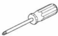
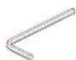
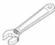
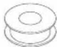
Table of Contents:
Warranties . Page 2
Installation Instructions.. .Pages 3 - 8
Clean and care.. Page 9
Maintenance.. Page 9
Cartridge Summary Reference Sheet Page 9
Classic Series Replacement Parts.. Page 12
For additional replacement parts, visit www.deltafacet.com
CAUTION: This system/device must be set by the installer to ensure safe, maximum temperature. Any change in the setting may raise the discharge temperature above the limit considered safe and may lead to hot water burns.
NOTICE TO INSTALLER: CAUTION! - As the installer of this valve, it is your responsibility to properly INSTALL and ADJUST this valve per the instructions given. This valve does not automatically adjust for inlet temperature changes, therefore, someone must make the necessary Rotational Limit Stop adjustments at the time of installation and further adjustments may be necessary due to seasonal water temperature change. YOU MUST inform the owner/user of this requirement by following the instructions. If you or the owner/user are unsure how to properly make these adjustments please refer to page 6 and if still uncertain, call us at 1-800-345-DELTA.
After installation and adjustment, you must affix your name, company name and the date you adjusted the Rotational Limit Stop to the caution
label provided and apply or attach the label to the back side of the closest cabinet door and the warning label to the water heater. Leave this Instruction Sheet for the owner's/user's reference.
WARNING: This pressure balanced or thermostatic bath valve is designed to minimize the effects of outlet water temperature changes due to inlet pressure changes, commonly caused by dishwashers, washing machines, toilets and the like. It may not provide protection from hot water burns when there is a failure of other temperature controlling devices elsewhere in the plumbing system, if the rotational limit stop is not properly set or if the hot water temperature is changed after the settings are made or if the water inlet changes due to seasonal changes. WARNING: Do not install a shut-off device on either outlet of this valve. When this type of device shuts off the water flow, it can defeat the ability of the valve to balance the hot and cold water pressures.
Lifetime Faucet and Finish Limited Warranty
Parts and Finish
All parts (other than electronic parts and batteries) and finishes of this Delta® faucet are warranted to the original consumer purchaser to be free from defects in material and workmanship for as long as the original consumer purchaser owns the home in which the faucet was first installed or, for commercial users, for 5 years from the date of purchase.
Electronic Parts and Batteries (if applicable)
Electronic parts (other than batteries), if any, of this Delta® faucet are warranted to the original consumer purchaser to be free from defects in material and workmanship for 5 years from the date of purchase or, for commercial users, for one year from the date of purchase. No warranty is provided on batteries.
Delta Faucet Company will replace, FREE OF CHARGE, during the applicable warranty period, any part or finish that proves defective in material and/or workmanship under normal installation, use and service. If repair or replacement is not practical, Delta Faucet Company may elect to refund the purchase price in exchange for the return of the product. These are your exclusive remedies.
Delta Faucet Company recommends using a professional plumber for all installation and repair. We also recommend that you use only genuine Deltareplacement parts.
Delta Faucet Company shall not be liable for any damage to the faucet resulting from misuse, abuse, neglect or improper or incorrectly performed installation, maintenance or repair, including failure to follow the applicable care and cleaning instructions.
Replacement parts may be obtained by calling the applicable number below or by writing to:
In the United States and Mexico:
DeltaFaucetCompany
Product Service
55 E. 111th Street
Indianapolis, IN 46280
1-800-345-DELTA (3358)
customerservice@deltafucet.com
In Canada:
Masco Canada Limited, Plumbing Group
Technical Service Centre
350 South Edgeware Road
St. Thomas, Ontario, Canada N5P 4L1
1-800-345-DELTA (3358)
customerservice@mascocanada.com
Proof of purchase (original sales receipt) from the original purchaser must be made available to Delta Faucet Company for all warranty claims unless the purchaser has registered the product with Delta Faucet Company. This warranty applies only to Delta ^ faucets manufactured after January 1,1995 and installed in the United States of America, Canada and Mexico.
DELTA FAUCET COMPANY SHALL NOT BE LIABLE FOR ANY SPECIAL, INCIDENTAL OR CONSEQUENTIAL DAMAGES (INCLUDING LABOR CHARGES) FOR BREACH OF ANY EXPRESS OR IMPLIED WARRANTY ON THE FAUCET.
Some states/provinces do not allow the exclusion or limitation of special, incidental or consequential damages, so these limitations and exclusions may not apply to you. This warranty gives you special legal rights. You may also have other rights which vary from state/province to state/province.
This is Delta Faucet Company's exclusive written warranty and the warranty is not transferable.
If you have any questions or concerns regarding our warranty, please view our Warranty FAQs at www.deltafaucet.com, email us at customerservice@deltafaucet.com or call us at the applicable number above.
Delta HDF Limited Warranty
All parts of the Delta HDF faucet are warranted to the original consumer purchaser to be free from defects in material and workmanship for a period of five (5) years. This warranty is made to the original consumer purchaser and shall be effective from date of purchase as shown on purchaser's receipt.
Delta will replace, FREE OF CHARGE, during the warranty period, any part which proves defective in material and/or workmanship under normal installation, use and service. Replacement parts can be obtained from your local dealer or distributor listed in the telephone directory or by returning the part along with the purchaser's receipt to our factory, TRANSPORTATION CHARGES PREPAID, at the address listed. THIS WARRANTY IS THE ONLY EXPRESS WARRANTY MADE BY DELTA. ANY CLAIMS MADE UNDER THIS WARRANTY MUST BE MADE DURING THE FIVE YEAR PERIOD REFERRED TO ABOVE. ANY IMPLIED WARRANTYIS, INCLUDING THE IMPLIED WARRANTY OF MERCHANTABILITY OR FITNESS FOR A
PARTICULAR PURPOSE, ARE LIMITED IN DURATION TO THE DURATION OF THIS WARRANTY. LABOR CHARGES AND/OR DAMAGE INCurred IN INSTALLATION, REPAIR OR REPLACEMENT AS WELL AS INCIDENTAL AND CONSEQUENTIALDAMAGES CONNECTED THEREWITH ARE EXCLUDING AND WILL NOT BE PAID BY DELTA.
Some states do not allow limitations on how long an implied warranty lasts, or the exclusion or limitation of incidental or consequential damages, so the above limitations or exclusions may not apply to you.
This warranty gives you specific legal rights, and you may also have other rights which vary from state to state.
This warranty is void for any damage to this faucet due to misuse, abuse, neglect, accident, improper installation, any use violative of instructions furnished by us or any use of replacement parts other than genuine Delta parts.
1 Cartridge Installation
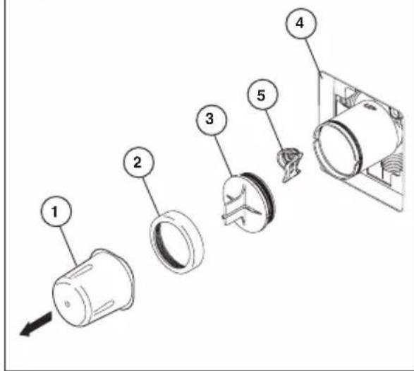
A.
Turn off water supplies. Remove cover (1), bonnet nut (2) and test cap (3) from the body. If this is not a thin wall mounting, the entire plasterguard (4) may be removed. If screen (5) is in place, remove before installing cartridge.
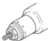
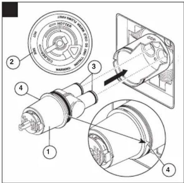
Rotate the cartridge (1) so the words "hot side" (2) appear on the left. Insert cartridge into valve body as shown. Make sure the cartridge tubes and O-rings (3) are properly seated in holes at the base of the body. Ensure the keys on the body are fully engaged with the slots in the body (4).
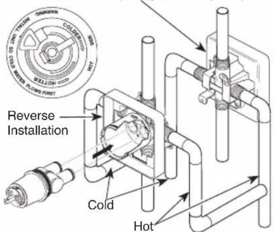
Back to back Installation C.
Normal Installation (changes not required)
For back to back or reverse installations (hot on right and cold on left) insert the cartridge with the "hot side" on the right. If you are not making a reverse or back to back installation skip this step and continue with step 1C.
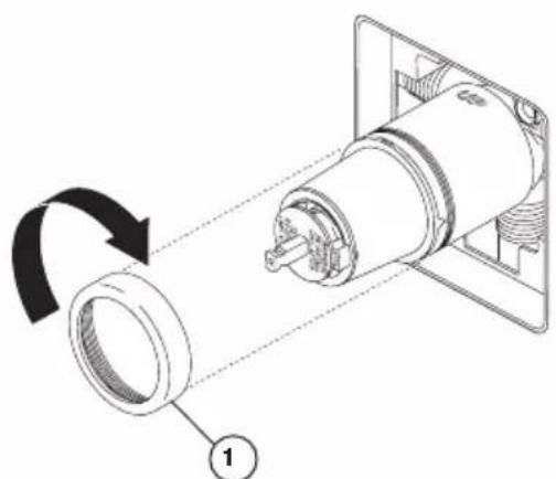
Slide bonnet nut (1) over the cartridge and thread onto the body. Hand tighten securely.
Installation
Showerhead and Tub Spout Installation
2
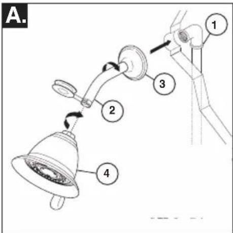
FOR SHOWERHEAD INSTALLATION: Connect top outlet (1) to shower arm (2) with proper fittings. To prevent damage to finish on shower arm, insert wall end of shower arm into shower flange (3) before screwing arm into riser connection. Thread showerhead (4) onto shower arm. Apply plumber tape to pipe threads on both ends. Do not overtighten showerhead.
B.
B.
B.
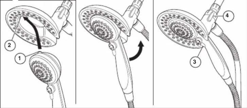
58045: To combine the two showers, insert the top tab (1) on the handshower into the slot (2) of the showerhead. Push the handshower into the showerhead until the two parts snap together.
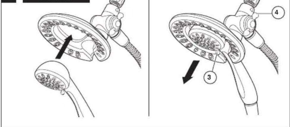
58065: To combine the two showers, push the handshower into the showerhead, then pull down on the handshower until locked with the showerhead.
If the showerhead moves when removing the handshower, hand tighten the connection between the showerhead and the shower arm.
To change spray modes, turn the lever (3) left or right to the desired setting. Turn knob (4) to change between showerhead only, showerhead and handshower or handshower only.
2
Showerhead and Tub Spout Installation
FOR TUB SPOUT INSTALLATION:
Refer to the installation instructions supplied with your spout. Do not connect deck mount spouts to in-wall valves. Do not use hand showers connected in lieu of a tub spout to a tub/shower valve. Do not use PEX tubing for tub spout drop.
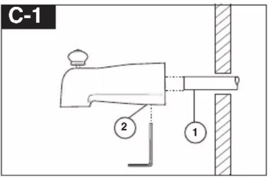
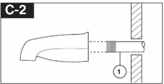
Slip-On Installation
The copper tube (1) must be 1/2 nominal copper. Important: If it is necessary to cut the copper tube, the end must be chamfered free of burrs to prevent cutting or nicking O-ring inside the spout. Slide spout over copper tube flush with the finished tub or wall surface. Tighten set screw (2), but do not overtighten.
Iron Pipe Installation
Install threaded pipe nipple (1) to extend past finished wall. Apply plumber tape to threads on pipe nipple and screw on tub spout.
Iron Pipe Installation
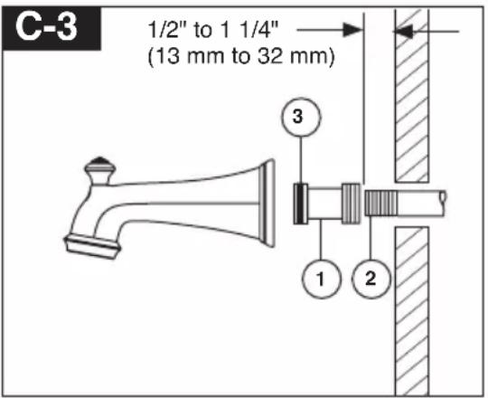
Installation of easy-on universal tub spout
Install pipe nipple so that end of nipple projects out from finished wall surface 1 / 2'' to 1 1 / 4'' (13 mm to 32 mm). Apply plumber tape or pipe dope to pipe threads. Hand tighten adapter (1) onto pipe nipple (2). Finish tightening with standard pipe wrench until a positive seal is implemented. Take care not to damage O-Ring (3) groove. Back of adapter (1) must not project more than 1'' (25 mm) from finished wall surface. Hand tighten tub spout onto adapter (1) taking care not to damage the O-Ring (3).
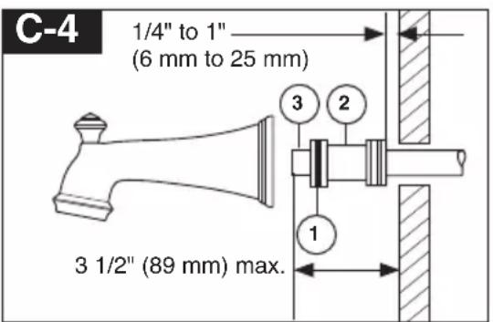
Copper Sweat Installation
Install adapter so the end of the adapter is 1/4'' to 1'' (6 mm to 25 mm) from finished wall. Remove O-ring (1) from adapter (2). Solder adapter to tube taking care to keep solder away from O-ring groove. CAUTION: NO SOLDER PERMITTED ON OUTSIDE DIAMETER OF ADAPTER ADJACENT TO O-RING GROOVE. Cut off tube (3) and replace O-ring on groove of brass adapter. Thread tub/spout onto adapter, taking care not to damage O-ring, and hand tighten until spout is firmly against finished wall and all slack is taken up behind wall.

Adjusting the Rotational Limit Stop - Identify RSL type from pages 6-7.
A.
IMPORTANT:
The Rotational Limit Stop is used to limit the amount of hot water available such that, if set properly, the user will not be scalded if the handle accidentally is rotated all the way to "hot" when a person is showering or filling a tub. The first position allows the LEAST amount of hot water to mix with the cold water in the system. In the first position the water will be the coldest possible when the handle is turned all the way to hot. As you move the Rotational Limit Stop counterclockwise, you progressively add more and more hot water in the mix. The last position to the left will result in the greatest amount of hot water to the mix, and the greatest risk of scald injury if someone accidentally turns the valve handle all the way to the hot side while showering or filling a tub.
WARNING: In some instances, setting the Rotational Limit Stop in the hottest position (full counterclockwise) could result in scald injury. It is necessary to adjust the Rotational Limit Stop so that the water coming out of the valve will not scald the user when the handle of the valve is rotated to the hot side.
- According to the majority of industry standards, the maximum allowable temperature of the water exiting the valve is 120^ (Your local plumbing codes may require a water temperature less than 120^ ).
- The Rotational Limit Stop may need to be re-adjusted seasonally if the inlet water temperature changes. For example, during the winter, the cold water temperature is colder than it is during the summer which could result in varying outlet temperatures. A water temperature for
a comfortable bath or shower is typically between 90^ - 110^
- Run the water so that the cold water is as cold as it will get and hot water is as hot as it will get. Place the handle on the stem (see page 8, step 4C) and rotate the handle counterclockwise until the handle stops.
- Place a thermometer in a plastic tumbler and hold in the water stream. If the water temperature is above 120^ , the Rotational Limit Stop must be repositioned clockwise to decrease valve outlet water temperature to be less than 120^ or to meet the requirements of your local plumbing codes.
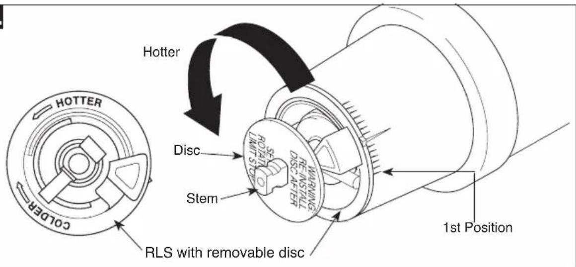
- To adjust the temperature of the water coming out of the valve, pull the disc back to a position where it is possible to remove the Rotational Limit Stop and readjust the teeth engagement position to the desired temperature. Clockwise will decrease the outlet temperature, counterclockwise will increase the outlet temperature. Temperature change per tooth (notch) could be 4^ - 16^ based on inlet water conditions. Repeat as necessary. Push disc until fully seated.
WARNING: Failure to re-install Disc after setting Rotational Limit Stop could result in scald injury.
- MAKE SURE COLD WATER FLOWS FROM THE VALVE FIRST. MAKE SURE WATER FLOWING FROM THE VALVE AT THE HOTTEST FLOW POSSIBLE DOES NOT EXCEED 120^ F OR THE MAXIMUM ALLOWED BY YOUR LOCAL PLUMBING CODE.
Installation
Adjusting the Rotational Limit Stop - Identify RSL type from pages 6-7.
IMPORTANT:
The Rotational Limit Stop is used to limit the amount of hot water available such that, if set properly, a scald injury is less likely to occur if the handle accidentally is rotated all the way to "hot" when a person is showering or filling a tub. The first position allows the LEAST amount of hot water to mix with the cold water in the system. In the first position the water will be the coldest possible when the handle is turned all the way to hot. As you move the Rotational Limit Stop counterclockwise, you progressively add more and more hot water in the mix. The last position to the left will result in the greatest amount of hot water to the mix, and the greatest risk of scald injury if someone accidentally turns the valve handle all the way to the hot side while showering or filling a tub.
WARNING: In some instances, setting the Rotational Limit Stop in the hottest position (full counterclockwise) could result in scald injury. It is necessary to adjust the Rotational Limit Stop so that the water coming out of the valve will not scald the user when the handle of the valve is rotated to the hot side.
-
According to the majority of industry standards, the maximum allowable temperature of the water exiting the valve is 120^ (Your local plumbing codes may require a water temperature less than 120^ ).
-
The Rotational Limit Stop may need to be re-adjusted seasonally if the inlet water temperature changes. For example, during the winter, the cold water temperature is colder than it is during the summer which could result in varying outlet temperatures. A water temperature for
a comfortable bath or shower is typically between 90^ - 110^
-
Run the water so that the cold water is as cold as it will get and hot water is as hot as it will get. Place the handle on the stem (see page 8, step 4C) and rotate the handle counterclockwise until the handle stops.
-
Place a thermometer in a plastic tumbler and hold in the water stream. If the water temperature is above 120^ , the Rotational Limit Stop must be repositioned clockwise to decrease valve outlet water temperature to be less than 120^ or to meet the requirements of your local plumbing codes.
-
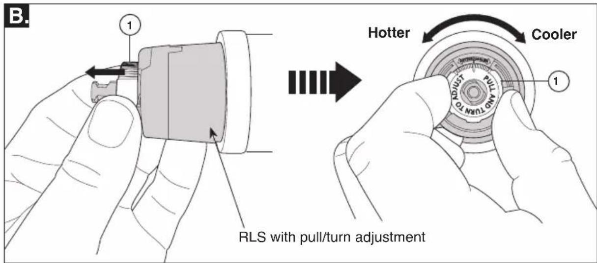
To adjust the temperature of the water coming out of the valve, pull the white Rotational Limit Stop (1) outward and rotate. Clockwise rotation will decrease the outlet temperature, counterclockwise rotation will increase the outlet temperature. Temperature change per tooth (notch) could be 4^ - 16^ based on inlet water conditions. Repeat as necessary. When finished, make sure that the Rotational Limit Stop is fully retracted into the seated position. WARNING: Do not take the Rotational Limit Stop apart.
-
MAKE SURE COLD WATER FLOWS FROM THE VALVE FIRST. MAKE SURE WATER FLOWING FROM THE VALVE AT THE HOTTEST FLOW POSSIBLE DOES NOT EXCEED 120^ F OR THE MAXIMUM ALLOWED BY YOUR LOCAL PLUMBING CODE.
4
Trim Installation
A.
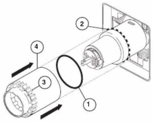
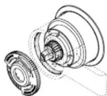
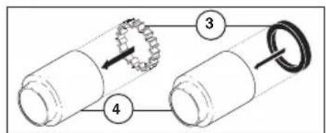
Slide O-ring (1) over cartridge and the bonnet nut (2). The O-ring, which acts as a spacer to steady the sleeve, should rest behind the bonnet nut.
If your model requires a spacer (3), insert it into the sleeve (4) and push it to the front. Slide the sleeve over the cartridge, body and O-ring.
C.
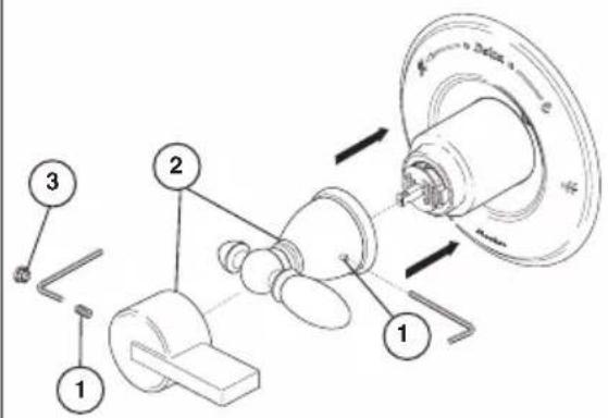
Using an Allen wrench to secure the set screw (1), install the handle (2) onto the stem. Insert plug button (3) (if your model has one) into set screw hole.
B.
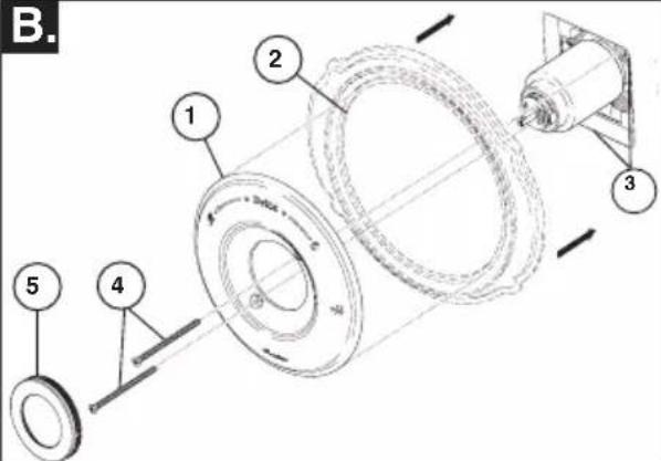
Escutcheon Installation for Models T14053, T14253, T14453, T14067, T14267 & T14467.
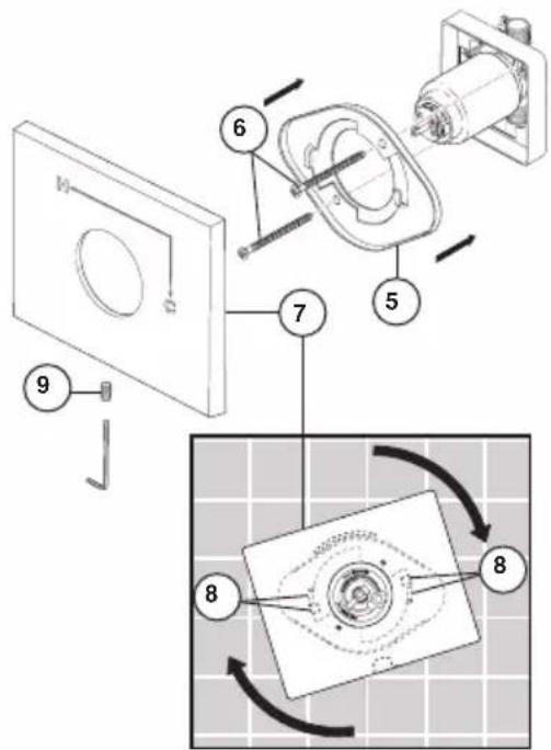
Secure the escutcheon (1) and backplate (2) (if your model has one) to the bracket (3) using the 2 screws provided (4). Do not overtighten escutcheon screws. If you are installing the Cassidy models T14097, T14297 & T14497:
Thread the cover (5) onto the escutcheon (1).
For models T14053, T14253, T14453, T14067, T14267 & T14467:
Install bracket (5) over the cartridge body using the 2 screws provided (6). Install escutcheon (7) by placing it over the bracket as shown and rotating it to lock the tabs (8). Secure the escutcheon to the bracket using set screw (9).
Clean and Care
Care should be given to the cleaning of this product. Although its finish is extremely durable, it can be damaged by harsh abrasives or polish. To clean, simply wipe gently with a damp cloth and blot dry with a soft towel.
Warning: Scrubbing Bubbles ^® Bathroom Cleaner and Lysol ^® Basin Tub and Tile Cleaner must not be used on the clear knob handles and levers. Use of these cleaners can result in cracked or severely damaged handles. If overspray gets onto the handles, immediately wipe them dry with a soft cotton cloth.
Maintenance
Faucet leaks from tub spout/showerhead: SHUT OFF WATER SUPPLIES.
Replace seats and springs—Repair Kit RP4993. Check condition of lower O-rings and replace if necessary RP14414. See Helpful Hints 1, 2, & 3.
If leak persists:
SHUT OFF WATER SUPPLIES. Replace valve cartridge RP46074. See Helpful Hints 1, 2, 3, 4 & 5
Unable to maintain constant water temperature:
Replace housing assembly with RP46074 or follow instructions in Helpful Hints 1, 2, 3, 4 & 5.
Helpful Hints:
-
Before removing valve cartridge assembly for any maintenance, be sure to note the position of the rotational limit stop on the cap. The valve cartridge assembly must always be put back in the same position. BE SAFE! After you have finished the installation, turn on valve to make sure COLD WATER FLOWS FIRST.
-
To remove valve cartridge from body, shut off
water supplies and remove handle and bonnet nut. Do not pry the valve cartridge out of the body with a screwdriver. Place handle on stem and rotate counterclockwise approximately 1/4 turn after the stop has been contacted. Lift valve cartridge out of body.
3. To remove seats and springs. Remove valve cartridge. Separate cap assembly from the housing assembly by rotating the cap assembly counterclockwise 90 o (degrees). Separate cap and housing assemblies.
4. If the water in your area has lime, rust, sand or other contaminants in it, your pressure balance valve will require periodic inspection. The frequency of the inspection will depend on the amount of contaminants in the water. To inspect valve cartridge remove it and follow the steps in note 1 above. Turn the valve to the full mix position and shake the cartridge vigorously. If there is a rattling sound, the unit is functional and can be reinstalled following instructions given in note 1 above. If there is no rattle, replace the housing assembly with the proper RP.
5. Push disc until fully seated. See page 6 for more details
Cartridge Summary Reference Sheet
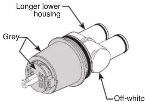
Monitor Series 1300/1400
Cartridge shipped before March 2006.
Cartridge shipped in July 2006 and after (prior to MultiChoice transition).
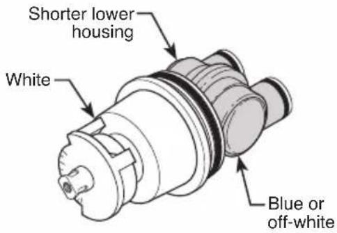
Order RP19804 to replace cartridge. Order RP19804 to replace cartridge.
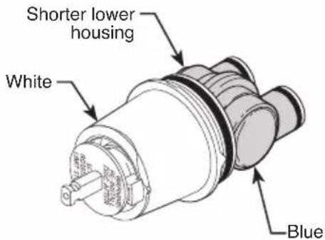
MultiChoice 13/14
Cartridge shipped from March 2006 to August 2014. Cartridge shipped in August 2014 and after.
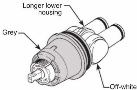
Order RP46074 to replace cartridge. Order RP46074 to replace cartridge.
NOTE: A running change for MultiChoice® 13/14 valves began August 2014, and features a new Rotational Limit Stop.
MultiChoice® 13/14 (Ceramic)
Cartridge shipping in select models (-CER).
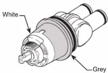
Order RP74236 to replace cartridge.
customerservice@deltafaucet.com
En Canadá:
Masco Canada Limited, Plumbing Group
Technical Service Centre
350 South Edgware Road
St. Thomas, Ontario, Canada N5P 4L1
1 800 345 DELTA (3358)
customerservice@mascocanada.com
customerservice@deltafaucet.com
Au Canada:
Masco Canada Limited, Plumbing Guoup
Thechnical Service Centre
350 South Edgware Board
Thomas, Ontario, Canada N5P 4L1
1-800-345-DELTA (3358)
customerservice@mascocanada.com
Monitor Series 1300/1400
For illustrative purposes, the replacement parts for the 13/14 Classic Series are shown on the following pages. For replacement parts on all other collections, please refer to the parts diagrams available on www.deltafaucet.com.