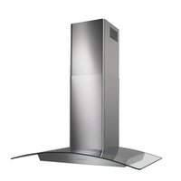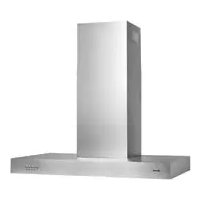
B5336SS - Basket BROAN - Free user manual and instructions
Find the device manual for free B5336SS BROAN in PDF.


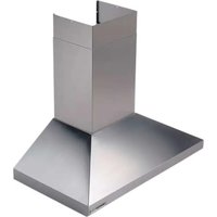
| Product Type | Chimney-style range hood |
| Brand | BROAN |
| Model | B5336SS |
| Category | Hood |
| Width | 91.4 cm (36 in) |
| Power Supply | 120 V, 60 Hz, AC |
| Lighting | 2 halogen bulbs 20 W max (type JC, 12 V, G4 base) |
| Controls | 4 push buttons: lighting, low/medium/high speeds, off |
| Number of Speeds | 3 (low, medium, high) |
| Material | Stainless steel |
| Grease Filters | 2 dishwasher-safe aluminum filters |
| Recirculation Filters | Optional, replace every 3 to 6 months (ref. S97018030) |
| Installation | With duct (external exhaust) or without duct (recirculation) with RK56 kit |
| Recommended Height Above Cooking Surface | 76 to 91.4 cm (30 to 36 in) |
| Motor | Permanently lubricated, integrated thermal protection |
| Use | Indoor use only |
| Warranty | Limited, see manual |
| Box Contents | Range hood, decorative flues, damper/connector, filters, screws, anchors, manual |
Frequently Asked Questions - B5336SS BROAN
User questions about B5336SS BROAN
0 question about this device. Answer the ones you know or ask your own.
Ask a new question about this device
Download the instructions for your Basket in PDF format for free! Find your manual B5336SS - BROAN and take your electronic device back in hand. On this page are published all the documents necessary for the use of your device. B5336SS by BROAN.
USER MANUAL B5336SS BROAN
To register this product visit: www.broan.com
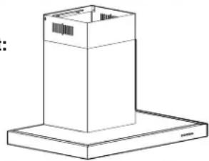
Page 1
READ AND SAVE THESE INSTRUCTIONS
- Use this unit only in the manner intended by the manufacturer. If you have questions, contact the manufacturer at the address or telephone number listed in the warranty.
- Before servicing or cleaning unit, switch power off at service panel and lock service disconnecting means to prevent power from being switch on accidentally. When the service disconnecting means cannot be locked, securely fasten a prominent warning device, such as a tag, to the service panel.
- Installation work and electrical wiring must be done by qualified personnel in accordance with all applicable codes and standards, including fire-rated construction codes and standards.
- Sufficient air is needed for proper combustion and exhausting of gases through the flue (chimney) of fuel burning equipment to prevent backdrafting. Follow the heating equipment manufacturer's guidelines and safety standards such as those published by the National Fire Protection Association (NFPA), the American Society for Heating, Refrigeration and Air Conditioning Engineers (ASHRAE) and the local code authorities.
- This product may have sharp edges. Be careful to avoid cuts and abrasions during installation or cleaning.
- When cutting or drilling into wall or ceiling, do not damage electrical wiring and other hidden utilities.
- Ducted fans must always be vented to the outdoors.
- Do not use this unit with any other solid-state speed control device.
- To reduce the risk of fire, use only steel ductwork.
- This unit must be grounded.
TO REDUCE THE RISK OF A RANGE TOP GREASE FIRE:
a) Never leave surface units unattended at high settings. Boilovers cause smoking and greasy spillovers that may ignite. Heat oils slowly on low or medium settings.
b) Always turn hood ON when cooking at high heat or when cooking flaming foods (i.e. Crépes Suzette, Cherries Jubilee, Peppercorn Beef Flambé).
c) Clean ventilating fans frequently. Grease should not be allowed to accumulate on fan or filters.
d) Use proper pan size. Always use cookware appropriate for the size of the surface element.
WARNING
TO REDUCE THE RISK OF INJURY TO PERSON(S) IN THE EVENT OF A RANGE TOP GREASE FIRE, OBSERVE THE FOLLOWING*:
- SMOTHER FLAMES with a close-fitting lid, cookie sheet, or metaltray, thenturnoff theburner. BECAREFUL TOPREVENT BURNS. IF THE FLAMES DO NOT GO OUT IMMEDIATELY, EVACUATE AND CALL THE FIRE DEPARTMENT.
- NEVER PICK UP A FLAMING PAN - You may be burned.
- DO NOT USE WATER, including wet dishcloths or towels - This could cause a violent steam explosion.
- Use an extinguisher ONLY if:
A. You know you have a Class ABC extinguisher and you know how to operate it.
B. The fire is small and contained in the area where it started.
C. The fire department has been called.
D. You can fight the fire with your back to an exit.
- Based on "Kitchen Fire Safety Tips" published by NFPA.
CAUTION
- For indoor use only.
- For general ventilating use only. Do not use to exhaust hazardous or explosive materials and vapors.
- To avoid motor bearing damage and noisy and/or unbalanced impeller, keep drywall spray, construction dust, etc. off power unit.
- Do not use over cooking equipment greater than 60,000 BTU/hr. as the blower motor will shut down intermittently.
- Your hood motor has a thermal overload which will automatically shut off the motor if it becomes overheated. The motor will restart when it will cool down. If the motor continues to shut off and restart, have the hood serviced.
- A maximum height of 36" above the cooktop is recommended for best capture of cooking impurities. The bottom of the hood MUST NOT BE LESS than 30" above the cooktop.
- Two installers are recommended because of the size of this hood.
- To reduce risk of fire and to properly exhaust air, be sure to duct air outside. Do not exhaust air into spaces within walls or ceilings or into attics, crawl spaces, or garages.
- Be careful when installing the decorative flue and hood, they may have sharp edges.
- Please read specification label on product for further information and requirements.
OPERATION
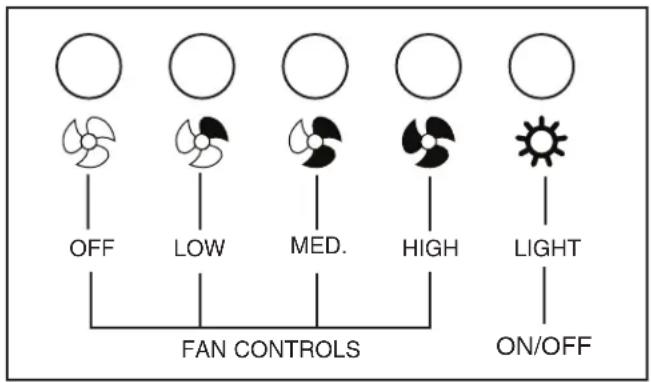
The hood is operated using the push buttons on the front panel. Push the light button to turn the lights on and off.
Push the fan controls to select low, medium, or high blower speed.
Push the OFF button to turn the blower off.
LIGHT BULBS
WARNING
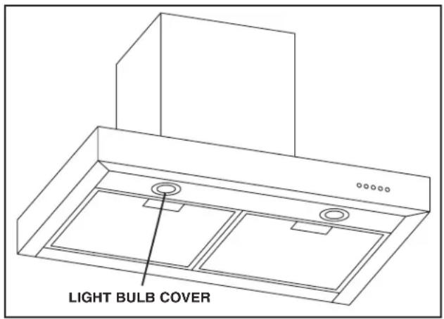
Bulbs may be hot. Always allow bulbs to cool down before removing them.
This range hood requires two halogen bulbs (Type JC, 12V, 20W Max, G-4 Base - included).
To change bulbs:
1. Remove light bulb cover by gently pushing it upward and turning it counterclockwise.
2. Replace bulb.
3. Re-install light bulb cover by gently pushing it upward and turning it clockwise.
CLEANING AND MAINTENANCE
Proper maintenance of the Range Hood will assure proper performance of the unit.
MOTOR
The motor is permanently lubricated and never needs oiling. If the motor bearings make excessive or unusual noise, replace the motor with the exact service motor. The impeller should also be replaced.
GREASE FILTER
The grease filter should be cleaned frequently. Use a warm detergent solution. Grease filter is dishwasher safe.
Clean all-metal filters in the dishwasher using a non-phosphate detergent. Discoloration of the filter may occur if using phosphate detergents, or as a result of local water conditions - but this will not affect filter performance. This discoloration is not covered by the warranty.
Remove grease filter by pushing back on the metal latch tab. This will disengage the filter from the hood. Tilt the filter downward and remove.
NON-DUCTED RECIRCULATION FILTERS
The non-ducted recirculation filters should be changed every 3-6 months. Replace more often if your cooking style generates extra grease, such as frying and wok cooking.
Rotate the filters to remove them from the blower and replace.
STAINLESS STEEL CLEANING
DO:
- Regularly wash with clean cloth or rag soaked with warm water and mild soap or liquid dish detergent.
Always clean in the direction of original polish lines. - Always rinse well with clear water (2 or 3 times) after cleaning. Wipe dry completely.
- You may also use a specialized household stainless steel cleaner.
DON'T:
- Use any steel or stainless steel wool or any other scrapers to remove stubborn dirt.
- Use any harsh or abrasive cleansers.
- Allow dirt to accumulate.
- Let plaster dust or any other construction residues reach the hood. During construction/renovation, cover the range hood to make sure no dust sticks to the stainless steel surface.
Avoid: When choosing a detergent
- Any cleaners that contain bleach will attack stainless steel
- Any products containing: chloride, fluoride, iodide, bromide will deteriorate surfaces rapidly.
- Any combustible products used for cleaning such as acetone, alcohol, ether, benzol, etc., are highly explosive and should never be used close to a range.
INSTALL THE DUCTWORK
(Ducted Hoods Only)
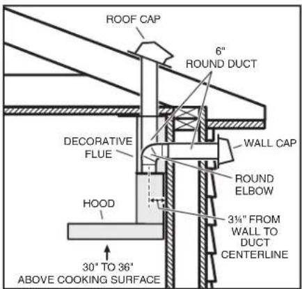
- Decide where the ductwork will run between the hood and the outside.
- A straight, short duct run will allow the hood to perform most efficiently.
- Long duct runs, elbows and transitions will reduce the performance of
the hood. Use as few of them as possible. Larger ducting may be required for best performance with longer duct runs.
- Install wall cap or roof cap. Connect round metal ductwork to cap and work back towards the hood location. Use duct tape to seal the joints between ductwork sections.
MEASURE THE INSTALLATION
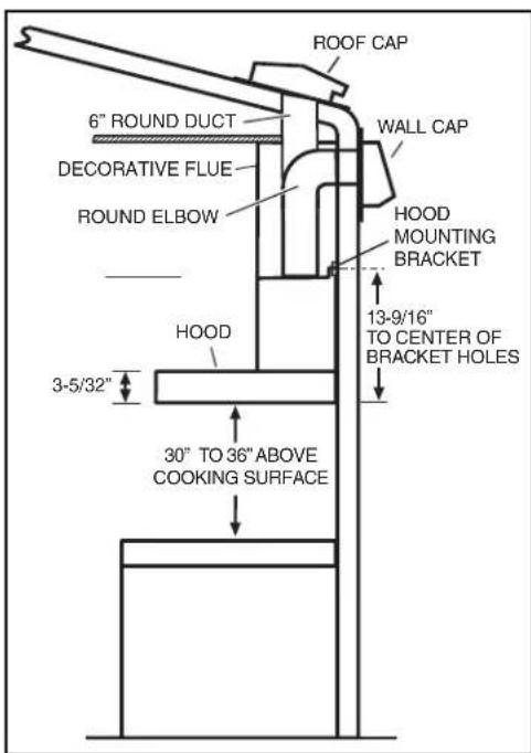
A maximum of 36" above cooktop is recommended for best capture of cooking impurities. The bottom of the hood MUST NOT BE LESS than 30" above the cooktop.
Distances over 36^ are at the installer and users discretion; providing that the ceiling height permits.
PREPARE THE HOOD
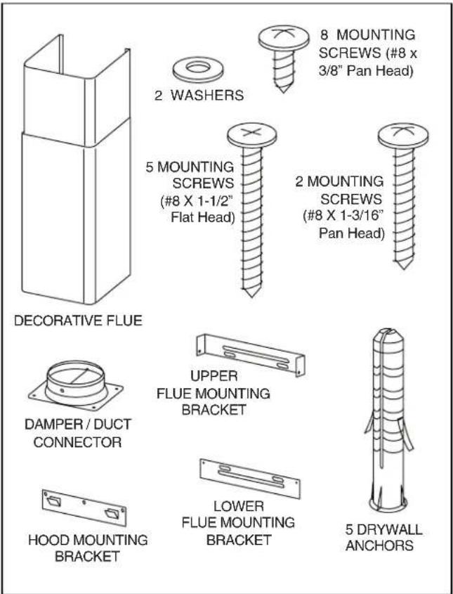
Unpack hood and check contents. You should receive:
1-Hood
1 - Decorative Flue Assembly
1 - Damper / Duct Connector
1 - Lower Flue Mounting Bracket
1 - Upper Flue Mounting Bracket
1 - Hood Mounting Bracket
2 - Aluminum Grease Filters (installed in hood)
1 - Parts Bag containing:
8 - Mounting Screws (#8 x 3/8" Pan Head)
5 - Mounting Screws (#8 x 1-1/2" Flat Head)
2 - Mounting Screws (#8 x 1-3/16" Pan Head)
5 - Drywall Anchors
2-Washers
1-Installation Manual
INSTALL THE WIRING
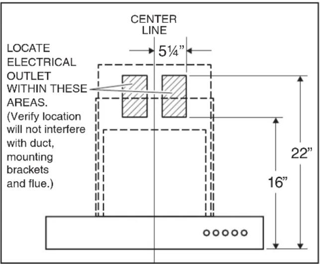
1. GROUNDING INSTRUCTIONS
This appliance must be grounded. In the event of an electrical short circuit, grounding reduces the risk of electric shock by providing an escape wire for the electric current. This appliance is equipped with a cord having a grounding wire with a grounding plug. The plug must be plugged into an outlet that is properly installed and grounded.
NOTE:
A recessed "clock" outlet is recommended.
- Position the electrical outlet within the space covered by the decorative flue and where it will not interfere with the round duct. Make sure the outlet is no further than 14" from where the cord exits from the hood and that the outlet does not interfere with a mounting bracket fastening area or where the decorative flue touches the wall.
INSTALL THE HOOD MOUNTING BRACKET
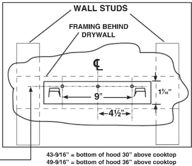
- Construct wood wall framing that is flush with interior surface of wall studs.
Make sure:
a) the framing is centered over installation location.
b) the height of the framing will allow the mounting bracket to be secured to the framing within the dimensions shown.
2. After wall surface is finished, carefully center and level the hood mounting bracket and secure it to wall framing with (3) # 8× 1 - 1 / 2 mounting screws. Tighten the screws completely.
Desired Hood Distance Above 36" High Cooktop (see note 1)
| 30" | 31" | 32" | 33" | 34" | 35" | 36" | ||
| Ceiling Height | Duct Method | Mounting Bracket Mounting Holes Location Above 36" High Cooktop — | ||||||
| 8 Feet | Ducted | 43-9/16" | 44-9/16" | 45-9/16" | 46-9/16" | 47-9/16" | 48-9/16" | 49-9/16" |
| Non-Ducted | 43-9/16" | 44-9/16" | 45-9/16" | |||||
| 9 Feet | Ducted | 43-9/16" | 44-9/16" | 45-9/16" | 46-9/16" | 47-9/16" | 48-9/16" | 49-9/16" |
| Non-Ducted | 43-9/16" | 44-9/16" | 45-9-16" | 46-9/16" | 47-9/16" | 48-9/16" | 49-9/16" | |
| 10 Feet (see note 2) | Ducted | 43-9/16" | 44-9/16" | 45-9/16" | 46-9/16" | 47-9/16" | 48-9/16" | 49-9/16" |
| Non-Ducted | 43-9/16" | 44-9/16" | 45-9/ 16" | 46-9/16" | 47-9/16" | 48-9/16" | 49-9/16" | |
Notes:
1 A maximum height of 36" above the cooktop is recommended for best capture of cooking impurities. The bottom of the hood MUST NOT BE LESS than 30" above the cooktop. Distances over 36" above the cooktop are at the installer's and user's discretion - providing that the ceiling height and flue length permit.
2 Requires 10-ft. flue extension accessory - Model Number FXN53SS.
INSTALL UPPER FLUE MOUNTING BRACKET
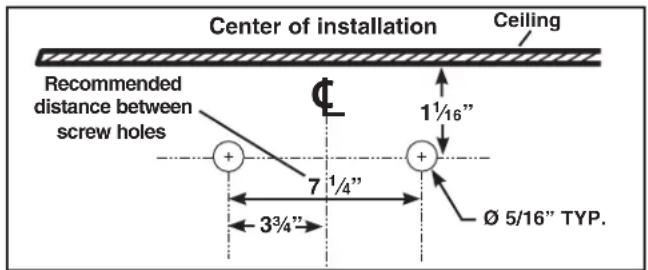
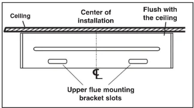
- Drill two 516 diameter holes where shown. Insert drywall anchors into the holes.
- Center the bracket over the hood location and flush with the ceiling. Make sure that the slots of the upper flue bracket are at the bottom. Secure the upper flue bracket to the wall using (2) #8 x 1½" mounting screws.
- Tighten the screws completely. Make sure that the bracket is tight against the wall.
INSTALL THE HOOD (Horizontally Ducted Hoods Only)
- DO NOT REMOVE the protective plastic film covering the decorative flue and the hood at this time.
- Lay the back side of the hood flat on a table. Use a piece of cardboard to avoid damaging the table or the hood.
- Attach damper / duct connector to top of hood using (4) #8 x 3/8" Pan Head mounting screws.
- Remove the grease filters by pushing back the metal latch tab and tilting filters downward to remove.
- Carefully rotate hood upright.
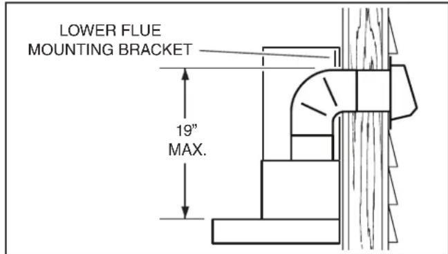
- To make sure there will be adequate clearance between top of hood and lower flue mounting bracket for ductwork: Elbow must be located below lower flue mounting bracket.
- Align the hood and center it above the hood mounting bracket. Gently lower the hood until it securely engages the bracket.
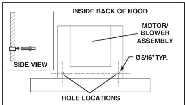
- With the hood hanging in place, drill through both holes located in the inside lower back of hood using a 5 / 16 drill bit. Insert the included drywall anchors into the drilled holes (one for each hole). Install (2) washers and (2) #8 x 1-3/16" pan head mounting screws through the hood back and into the drywall anchors. Verify that the hood is centered and leveled. Tighten all screws completely.
- Reinstall grease filters by aligning rear filter tabs with slots in the hood. Push back the metal latch tab, push filter into position and release. Make sure filters are securely engaged after installation.
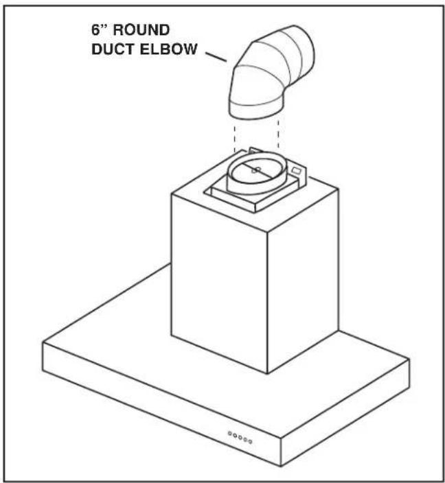
- Measure and install 6^ round steel ductwork to roof cap or wall cap and 90^ elbow over duct collar on hood. Use duct tape to make all joints secure and air tight.
- Plug hood power cord into the outlet.
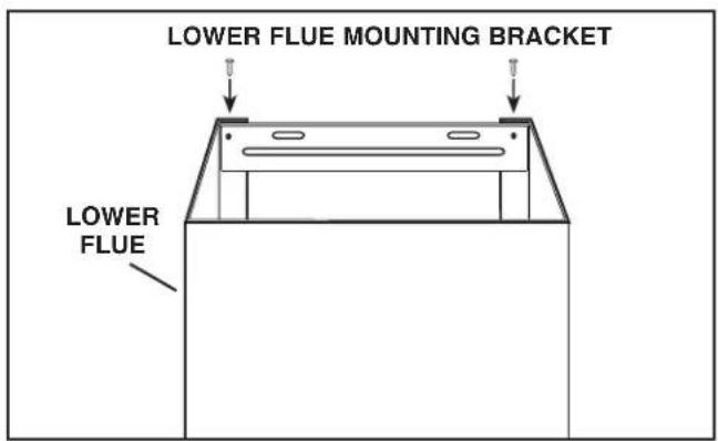
NOTE: 10-ft. ceilings require 10-ft. Flue Extension Model FXN53SS (purchase separately). Discard the upper flue supplied with your hood and replace it with the Model FXN53SS flue extension.
- Remove the upper flue from inside the lower flue. Install the lower flue bracket to the lower flue using (2) flue bracket screws # 8 × 3 / 8 make sure that the slots are at the top. Remove protective plastic film covering the lower flue only. Carefully replace the upper flue inside the lower flue.
- Carefully place both flues into the recessed area of hood top. Make sure tabs on the lower flue are pointing down and engage with the slots on the top of the hood.
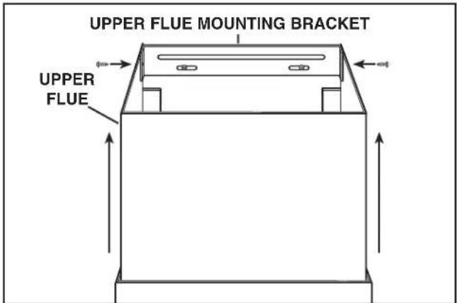
- Slide the upper flue upward until it is aligned with its upper mounting bracket. The bracket should be inside the flue. Secure the upper flue to the upper flue mounting bracket using (2) #8 x 3/8" mounting screws.
- Remove any protective plastic remaining on hood.
INSTALL THE HOOD (Vertically Ducted Hoods Only)
- DO NOT REMOVE the protective plastic film covering the decorative flue and the hood at this time.
- Lay the back side of the hood flat on a table. Use a piece of cardboard to avoid damaging the table or the hood.
- Attach damper / duct connector to top of hood using (4) #8 x 3/8" Pan Head mounting screws.
- Remove the grease filters by pushing back the metal latch tab and tilting filters downward to remove.
- Carefully rotate hood upright.
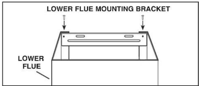
NOTE: 10-ft. ceilings require 10-ft. Flue Extension Model FXN53SS (purchase separately). Discard the upper flue supplied with your hood and replace it with the Model FXN53SS flue extension.
- Remove the upper flue from inside the lower flue. Install the lower flue bracket to the lower flue using (2) flue bracket screws #8 x 3/8", make sure that the slots are at the top. Remove protective plastic film covering both flues. Carefully replace the upper flue inside the lower flue.
- Carefully place both flues into the recessed area of hood top. Make sure tabs on the lower flue are pointing down and engage with the slots on the top of the hood.
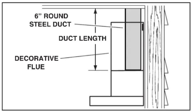
- Measure and install steel ductwork to hood duct connector. Use duct tape to make all joints secure and air tight.
- Hold hood up close to wall mounting location and plug power cord into wall outlet.
- Align the hood and center it above the hood mounting bracket. Make sure ductwork on hood lines up and attaches to ductwork in ceiling. Gently lower the hood until it securely engages the bracket.
- Use duct tape to make all joints secure and air tight.
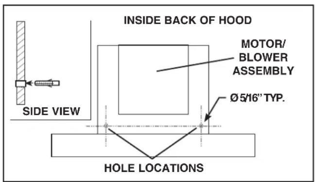
- With the hood hanging in place, drill through both holes located in the inside lower back of hood using a 5 / 16 drill bit. Insert the included drywall anchors into the drilled holes (one for each hole). Install (2) washers and (2) # 8 × 1 - 3 / 16 pan head mounting screws through the hood back and into the drywall anchors. Verify that the hood is centered and leveled. Tighten all screws completely.
- Reinstall grease filters by aligning rear filter tabs with slots in the hood. Push back the metal latch tab, push filter into position and release. Make sure filters are securely engaged after installation.
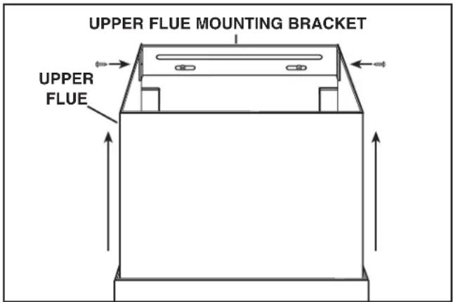
- Slide the upper flue upward until it is aligned with its mounting bracket. The bracket should be inside the flue. Secure the upper flue to the upper flue mounting bracket using (2) #8 x 3/8" mounting screws.
- Remove any protective plastic remaining on hood.
INSTALL THE HOOD (Non-Ducted Hoods Only)
NON-DUCT KIT MODEL RK56 CONTENTS
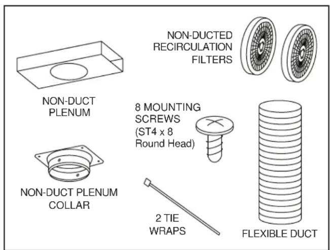
NOTE: Non-ducted installations require Non-Duct Kit, Model RK56 (purchase separately).
- CAUTION: Do not use plastic or rigid metal duct.
- Do not remove the protective plastic film covering the decorative flue and the hood at this time.
- Lay the back side of the hood flat on a table. Use a piece of cardboard to avoid damaging the table or the hood.
- Attach damper / duct connector to top of hood using (4) #8 x 3/8" Pan Head mounting screws.
-
Remove damper flaps from damper / duct connector and discard flaps.
-
Remove the grease filters by pushing back the metal latch tab and tilting filters downward to remove.
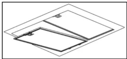
-
Attach non-duct collar to non-duct plenum using (4) ST4 x 8 round head screws.
-
Measure distance "A". This will be the length of the extended flex duct.
-
Attach aluminum flexible duct to the damper / duct connector with a tie wrap.
-
Attach flexible duct to non-duct plenum collar and secure with tie wrap. Tape all joints with duct tape.
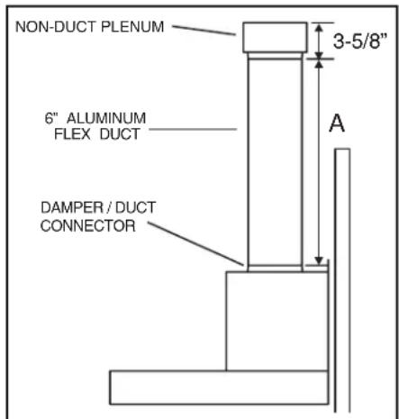
NOTE: 10-ft. ceilings require 10-ft. Flue Extension Model FXN53SS (purchase separately). Discard the upper flue supplied with your hood and replace it with the Model FXN53SS flue extension.
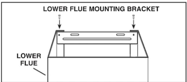
- Remove the upper flue from inside the lower flue. Install the lower flue bracket to the lower flue using (2) flue bracket screws #8 x 3/8", make sure that the slots are at the top. Remove protective plastic film covering both flues. Carefully replace the upper flue inside the lower flue.
- Carefully place both flues into the recessed area of hood top. Make sure tabs on the lower flue are pointing down and engage with the slots on the top of the hood.
-
Attach non-duct plenum with collar to upper flue using (4) ST4 x 8 round head screws.
-
Hold hood up close to wall mounting location and plug power cord into wall outlet.
- Align the hood and center it above the hood mounting bracket. Gently lower the hood until it securely engages the bracket.
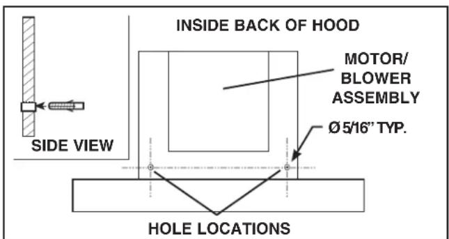
- With the hood hanging in place, drill through both holes located in the inside lower back of hood using a 5 / 16 drill bit. Insert the included drywall anchors into the drilled holes (one for each hole). Install (2) washers and (2) #8 x 1-3/6" pan head mounting screws through the back of the hood and into the drywall anchors. Verify that the hood is centered and leveled. Tighten all screws completely.
- Attach (2) two non-duct recirculation filters to sides of blower by aligning key lock slot and rotating until filters lock into place.
For replacement non-duct recirculation filters - purchase S97018030 or ROUNDFILTER.
- Reinstall grease filters by aligning rear filter tabs with slots in the hood. Push back the metal latch tab, push filter into position and release. Make sure filters are securely engaged after installation.
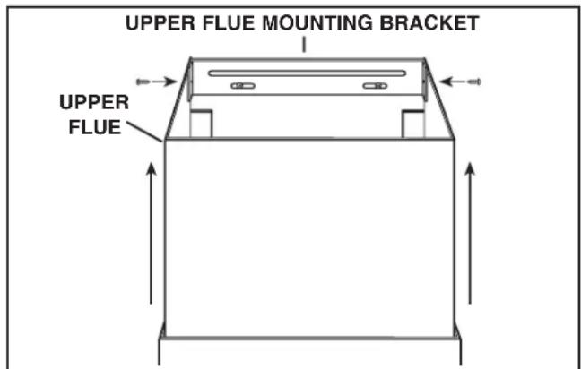
- Slide the upper flue upward until it is aligned with its mounting bracket. The bracket should be inside the flue. Secure the upper flue to the upper flue mounting bracket using (2) #8 x 3/8" mounting screws.
- Remove any protective plastic remaining on hood.
SERVICE PARTS
KEY PART NO. DESCRIPTION QTY.
| 1 | S99528454 | Decorative Upper and Lower Flues 1 | |
| 2 | S99526974 | Motor / Blower Assembly 1 | |
| 3 | S99526975 | Light Socket Assembly 2 | |
| 4 | S99527010 | Light Trim Ring / Lens Assembly 2 | |
| 5 | S99526976 | Push Button Assembly 1 | |
| 6 | S97018027 | Aluminum Grease Filters (2 per hood) B5330SS 1 | |
| S97018028 | Aluminum Grease Filters (3 per hood) B5336SS 1 | ||
| 7 | S97018030 | Non-Duct Recirculation Filters (pair) 1 | |
| 8 | S99526983 | Damper / Duct Connector 1 | |
| 9 | S99526984 | 6" Dia. Expandable Flexible Aluminum Duct 1 | |
| 10 | S99526985 | Non-Duct Plenum Assembly 1 | |
| 11 | S99526987 | Hood Mounting Bracket 1 | |
| 12 | S99526989 | Lower Flue Mounting Bracket 1 | |
| 13 | S99526991 | Upper Flue Mounting Bracket 1 | |
| 14 | S99527012 | Capacitor 1 | |
| 15 | S99527013 | Plastic Cover 1 | |
| S99527011 | Transformer (not shown) 1 | ||
| S99528455 | Parts Bag (not shown) 1 |
Order service parts by Part No. - not by Key No.
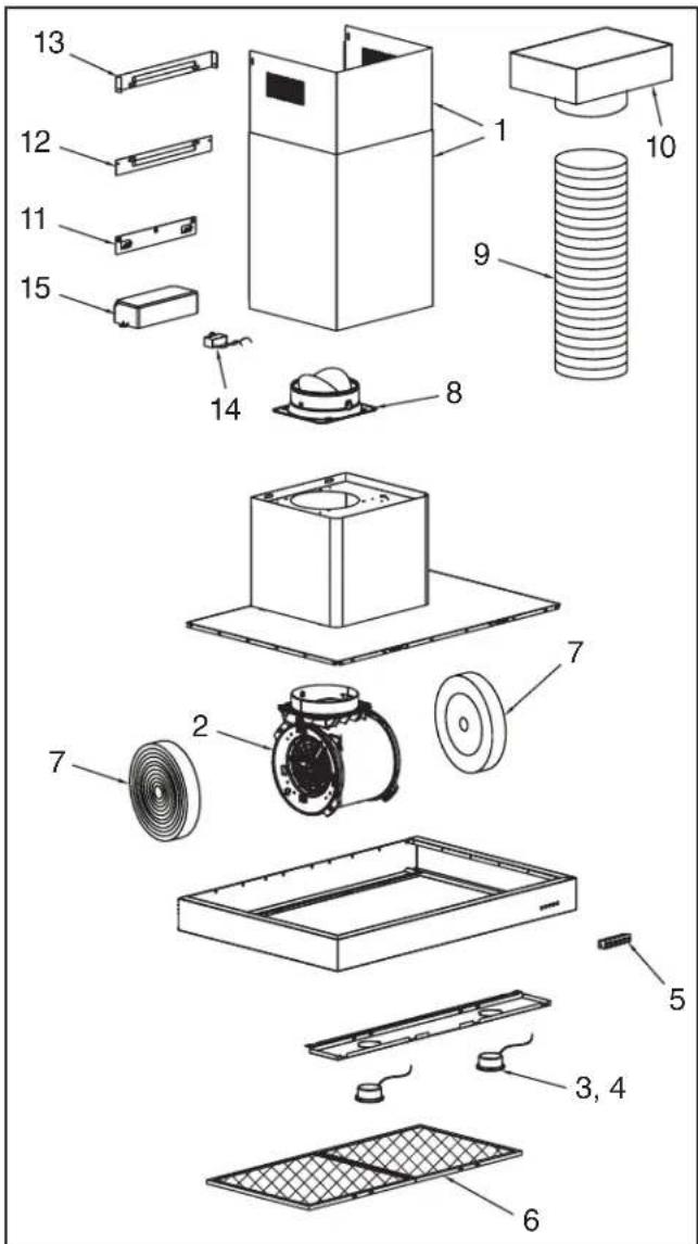
Replacement parts can be ordered on our website: www.broan.com
HOTTE DE
Warrty Period and Exclusions: Broan-NeTone LLC (the "Company") warrants to the original consumer purchaser of its product ("you") that the product (the "Product") will be free from material defects in the Product or its workmanship for a period of one TTI year from the date of original purchase.
The limited warranty period for any replacement parts provided by the Company and for any Products repaired or replaced under this limited warranty shall be the remainder of the original warranty period.
This warranty does not cover fluorescent lamp starters, tubes, halogen and incandescent bulbs, fuses, filters, ducts, roof caps, wall caps and other accessories for ducting that may be purchased separately and installed with the Product. This warranty also does not cover (a) normal maintenance and service, (b) normal wear and tear. (c) any Products or parts which have been subject to misuse, abuse, abnormal usage, negligence, accident, improper or insufficient maintenance, storage or repair (other than repair by the Company). (d) damage caused by faulty installation, or installation or use contrary to recommendations or instructions, (e) any Product that has been moved from its original point of installation. (f) damage caused by environmental or natural elements. (g) damage in transit. (h) natural wear of finish. (i) Products in commercial or nonresidential use, or (j) damage caused by fire, flood or other act of God. This warranty covers only Products sold to original consumers in the United States by the Company or U.S. distributors authorized by the Company.
This warranty supersedes all prior warranties and is not transferable from the original consumer purchaser
No Other Warranties: This Limited Warranty contains the Company's sole obligation and your sole remedy for defective products. The foregoing warranties are exclusive and in lieu of any other warranties, express or implied. THE COMPANY DISCTLMAS AND EXCLUDING ALL OTHER EXPRESS WARRANTY. AND DISCLAIMS AND EXCLUDING ALL WARRANTYES IMplied BY LAW. INCLUDING WITHOUT LIMITATION THOSE OF MERCHANTABILITIES AND FITNESS FOR A PARTICULAR PURPOSE. TO the extent that applicable law prohibits the exclusion of implied warranties, the duration of any applicable implied warranty is limited to the period specified for the express warranty above. Some states do not allow limitations on how long an implied warranty lasts, so the above limitation may not apply to you. Any oral or written description of the Product is for the sole purpose of identifying it and shall not be construed as an express warranty.
whent t the extent of such prohibition or invalidity, without invalidating the remainder of such provision or the other remaining provisions of the Limited Warranty.
Exclusion of Damages: THE COMPANY'S OBLIGATION TO PROVIDE REPLACEMENT PARTS, OR REPAIR OR REPLACE. AT THE COMPANY'S OPTION, SHALL BE YOUR SOLE AND EXCLUSIVE REMEDY UNDER THIS LIMITED WARRANTY AND THE COMPANY'S SOLE AND EXCLUSIVE OBLIGATION. THE COMPANY SHALL NOT BE LIABLE FOR INCIDENTAL, INDIRECT, CONSEQUENTIAL OR SPECIAL DAMAGES ASING OUT OF OR IN CONNECTION WITH THE PRODUCT, ITS USE OR PERFORMANCE.
Some states do not allow the exclusion or limitation of incidental or consequential damages, so the above limitation or exclusion may not apply to you. This warranty gives you specific legal rights, and you may also have other rights, which vary from state to state.
This warranty covers only replacement or repair of defective Products or parts thereof at the Company's main facility and does not include the cost of field service travel and living expenses.
any
The Company will not reimburse you for any expenses incurred by you in repairing or replacing any defective Product, except for those incurred with the Company's prior written permission.
How to obtain Warranty Service: To quality for warranty service, you must (a) notify the Company at the address or telephone number stated below within seven (7) days of discovering the covered defect, (b) give the model number and part identification and (c) describe the nature of any defect in the Product or part. At the time of requesting warranty service, you must present evidence of the original purchase date. If you cannot provide a copy of the original written limited warranty, then the terms of the Company's most current written limited warranty for your particular product will control. The most current limited written warranties for the Company's products can be found at: www.broan.com.
Bran-NuTone LLC 926 West State Street, Hartford, WI 53027 www.brian.com 800-637-1453
Garantie limitee
Pepre t 11 an a comr de la date d'achat originale.
Broan-NuTone LLC 926 West State Street, Hartford, WI 53027 www.broan.com 800-637-1453