
Laser FF 95 - Heating ZIBRO - Free user manual and instructions
Find the device manual for free Laser FF 95 ZIBRO in PDF.
| Product type | Liquid fuel heater (petroleum) |
| Brand | Zibro |
| Model | Laser FF 95 |
| Heating power (Low / Med / High) | 3.1 kW / 6.3 kW / 9.5 kW |
| Fuel consumption (Low / Med / High) | 0.38 L/h / 0.73 L/h / 1.08 L/h |
| Nominal efficiency | 92% |
| Power supply | 230 V ~ 50 Hz (estimated) |
| Power consumption (ignition / standby) | 280 W / 80 W |
| Fuel type | Non-aqueous petroleum (Zibro Extra or Zibro Kristal) |
| Recommended heating volume | 130 – 440 m³ |
| Fan air flow (Low / Med / High) | 0.8 / 1.9 / 2.9 m³/min |
| Temperature setting | 10 °C to 32 °C |
| Main functions | Programmable timer, room thermostat, SAVE mode, child safety |
| Safety | Overheat protection, automatic shutdown, key lock |
| Routine maintenance | Weekly cleaning of air filter, monthly cleaning of fuel filter |
| Warranty | 4 years (excluding consumables) |
Frequently Asked Questions - Laser FF 95 ZIBRO
User questions about Laser FF 95 ZIBRO
0 question about this device. Answer the ones you know or ask your own.
Ask a new question about this device
Download the instructions for your Heating in PDF format for free! Find your manual Laser FF 95 - ZIBRO and take your electronic device back in hand. On this page are published all the documents necessary for the use of your device. Laser FF 95 by ZIBRO.
USER MANUAL Laser FF 95 ZIBRO
| F | MANUEL D'UTILISATION | 3 |
| GB | OPERATING INSTRUCTIONS | 26 |
| NL | GEBRUIKSAANWIJZING | 49 |
natural_image
Technical line drawing of a mechanical device with no visible text or symbolsnatural_image
Technical line drawing of a rectangular electronic component with mounting holes and a central slot (no text or symbols)natural_image
Technical line drawings of four mechanical components: two rectangular plates with holes, a threaded screw, and a conical screw (no text or symbols)
natural_image
Simple line drawing of a rectangular arch structure with two side panels (no text or symbols)
natural_image
Simple line drawing of a four-legged stool (no text or symbols)Porte tuyau (1) Fixation de tuyauterie (1)
natural_image
Technical illustration of a mechanical assembly with three views: two screws, one threaded component, and one cylindrical part (no text or symbols)natural_image
Line drawing of a U-shaped pipe fitting with layered cylindrical components (no text or symbols)natural_image
Technical line drawing of a metal bracket component (no text or symbols)natural_image
Line drawing of a 10-inch pipe fitting (no text or symbols)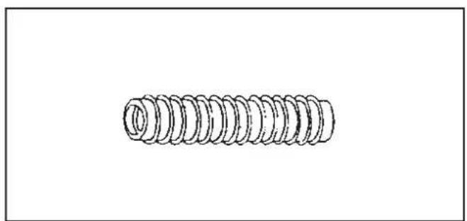
natural_image
Simple line drawing of a coiled spring (no text or symbols)natural_image
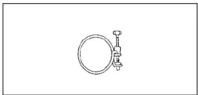
Simple line drawing of a mechanical clamp or bracket with a circular ring and fastener (no text or symbols)Fig. 5 Fig. 6
natural_image
Line drawing of a hand holding a tool with a ruler and measurement markings (no text or symbols)Fig. 14
Fig. 13
natural_image
Line drawing of a hand holding a small electronic device with a handle and label (no text or symbols present)(b)
).
natural_image
Technical line drawing of a mechanical bracket with screws and a handle (no text or symbols)Fig. 15
Chapter 1, INSTALLATION
Dear Sir, Madam,
Congratulations with your purchase of a portable domestic heater. You have purchased a quality product, which will serve you for many years to come. This, of course, provided you use the heater correctly. Please read these Directions for Use first, to ensure maximum lifetime for your heater.
Your heater comes with a 48-month manufacturer's warranty on all defects in materials or workmanship.
We wish you a warm and comfortable time with your heater.
Yours sincerely,
PVG Holding b.v.
Customer Service Department
1 READ THE DIRECTIONS FOR USE FIRST.
2 IN CASE OF ANY DOUBT, CONTACT YOUR ZIBRO DEALER.
WHAT YOU NEED TO KNOW IN ADVANCE
THE RIGHT FUEL
Only use Class C1 paraffin fuel in accordance with BS2869: Part 2, or equivalent. Your Zibro heater has been designed for use with high-quality water-free pure paraffin oil, such as Zibro Extra, Zibro Kristal or Zibro Bio. Only fuels of this kind will ensure clean and proper burning. Lower quality fuel may result in:
▶increased possibility of malfunctioning
▶incomplete burning
▶reduced heater lifetime
▶ smoke and/or smells
▶ deposits on the grid or mantle
Using the right fuel is therefore essential for safe, efficient, and comfortable use of your heater.
Always refer to your local Zibro dealer for the right fuel for your heater.

- The first time you ignite your heater it will smell like 'new' for a short time.
- Store your fuel in a cool and dark place.
- Fuel has a limited shelf life. Start every heating season with renewed fuel.
- The right quality of fuel will be assured, when you use Zibro Extra or Zibro Kristal for your heater.
- If you change to another brand and/or type of paraffin oil, you must first finish up all the remaining fuel in the heater.
TIPS FOR SAFE USE
1 Make sure that children are always aware of the presence of a burning heater.
2 Position the front of the heater at a distance of minimum 1.5 metres from walls, curtains, and furniture.
3 Do not use the heater in dusty rooms. You will not have optimum burning in such rooms. Do not use the heater in the immediate surrounding of a bath, a shower or a swimming pool.
4 Switch off the heater, before you leave or go sleeping. Unplug the heater as well, when you go away for a longer period of time (e.g. holidays).
5 Store and move fuel only in suitable tanks and jerrycans.
6 Make sure that the fuel is not exposed to heat or extreme temperature changes. Always store the fuel in a cool, dry and dark place (sunlight will affect the quality).
7 Never use the heater in places where harmful gasses or fumes may be present (e.g. exhaust gasses or paint fumes).
8 Beware that the grid of the heater becomes hot. If the appliance is covered there is a risk of fire.
9 Use only in accordance with state and/or local regulations, ordinances and codes.
10 Make sure the heater is on a level surface during operation
11 Do not service or refuel heater while in operation or still hot.
12 Do not operate in areas exposed to flammable vapors or high duel level to avoid fire or explosion.
13 This appliance is not intended for use by persons (including children) with reduced physical, sensory or mental capabilities, or lack of experience and knowledge, unless they have been given supervision or instruction concerning use of the appliance by a person responsible for their safety.
Chapter 1, INSTALLATION
1. Introduction
This chapter contains all the relevant information, specifically:
• Installation specifications
• List of installation tools
- Basic requirements for the installation of the fuel tank
- Instructions for the installation of the Laser System
The heater can be installed at any location, on condition that there is full compliance with electrical, fuel and emission regulations.
Before you start installing the heating system (including electrical wiring and fuel supply equipment), check the local building and fire safety regulations. The requirements stipulated in these regulations must be respected in order to guarantee a legally approved installation and correct operation.

The heater was designed to be used to a maximum altitude of 1000m above sea level. Contact your dealer for the necessary adjustments if you wish to use it at a higher altitude.
2. Moving the heater
In addition to the space required for the heater, extra room must be kept free for air circulation. The Laser System can be placed on any type of flooring and operate safely, unless fuel or fire safety regulations specify otherwise. Check the gaps in the manner stipulated in the instructions in the manual.
Recommended tool kit
- Crosshead screwdriver
- Steel tape measure
- Felt-tip pen or pencil
- Cement for exterior use
- Electric drill (clockwise and anti-clockwise recommended)
- Hole cutting saw, jig saw or other tools suitable for sawing a hole of 70\~80 mm for the exhaust pipe
- Long drill
- Standard screwdrivers
- Adjustable spanners (various sizes)
- Copper tube cutter
11.Reamer
12.Volt, Ohmmeter
13.Spirit level - Plumber's tape for tube screw thread
- Small range of self-tapping screws
- Range of pliers (pin tongs, needle nose pliers, cutting pliers, locking pliers)
- Insulated screwdriver
- Protective material for your floor
- Container for fuel exhaust pipe
3. The electrical supply system
The electrical system must be protected from overloads by an at least 5-Ampere fuse or contact breaker.

Some installations (such as for use in mobile homes) must be fitted with a permanent connection to the household power circuits. This must be done by a recognised electrician.
4. Fuel tank
Heater fuel (exclusively water-free, pure paraffin oil) in 200/1000 litre storage tanks located outside. If large tanks are used, a pressure regulator with a max. of 2.5 PSI ( ± 0.17 bar) must be fitted at the inlet on the heater. This must be carried out in strict adherence to all local standards and/or building regulations.
Chapter 1, INSTALLATION
5. Wiring for the room temperature sensor
A temperature sensor that can be fitted to a wall measures the room temperature in order to automatically regulate the heating. The standard sensor wire is approximately 2.5 m long.

The sensor may not be placed in a draught, direct sunlight or the warm air flowing out of the heater. This may cause incorrect temperature indications.
6. Unpacking
Save all packaging materials for possible future transportation.
A) Remove the cardboard (drilling) template and the user's manual from the packaging.
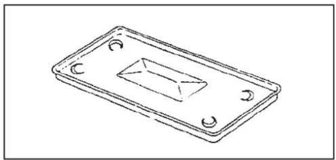
B) Remove the base plate and the box with the installation kit from the packaging.
C) Remove the heater from the packaging.
D) Remove the plastic bag covering the heater.
E) Remove the plastic bag containing the parts.
F) Remove the exhaust pipe from the bottom of the box.
G) Check that all parts are present.

Only the standard feed and exhaust system is supplied with the heater.
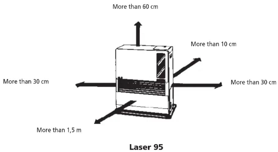
Fig. 1-1: Gaps heater/exhaust pipe
Chapter 1, INSTALLATION
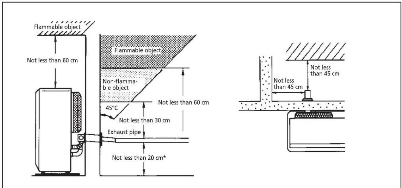
* This clearance has to be present also in case of snowfall, etc.
Fig. 1-1 (continued) gaps heater/exhaust pipe
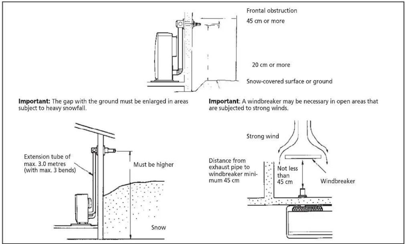
Fig. 1-2 Gaps heater/exhaust pipe
Chapter 1, INSTALLATION
After using the installation template as a guide for the drilling of the hole for the exhaust pipe, the Laser can be installed normally, according to the procedure in the illustration.
If the template is lost or the heater has to be moved, these are the dimensions and locations of the holes for the fuel pipe and exhaust pipe.
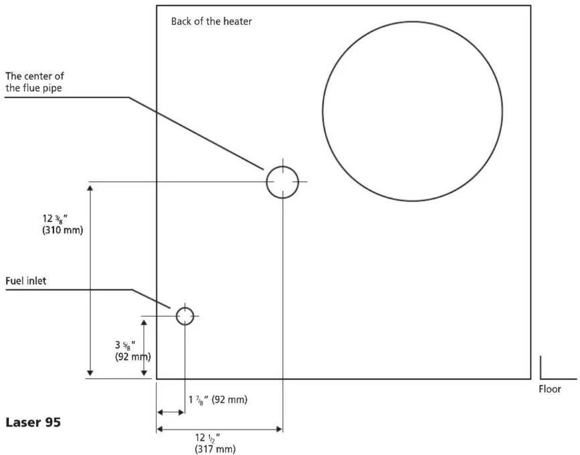
Fig. 1-3 Template

Do not remove any components from the heater. Always contact your dealer if repairs are required.
If the electricity cable is damaged, this may only be replaced with type H05 VV-F and by a recognised installer.
Chapter 1, INSTALLATION
Standard installation parts
The following list of standard installation parts is supplied with your heater. It may be necessary to order extra parts from your Zibro dealer if other installation methods are required.
natural_image
Line drawing of a rectangular electronic component with mounting holes and a central slot (no text or symbols)Base plate (1) Wall brackets (2 set)

natural_image
Technical line drawings of four different metal bracket components: two rectangular plates with holes, a threaded screw, and a conical screw (no text or symbols present)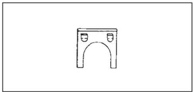
natural_image
Simple line drawing of a rectangular arch structure with two side panels (no text or symbols)
natural_image
Simple line drawing of a four-legged stool (no text or symbols)Pipe holder (1) Pipe lock (1)

natural_image
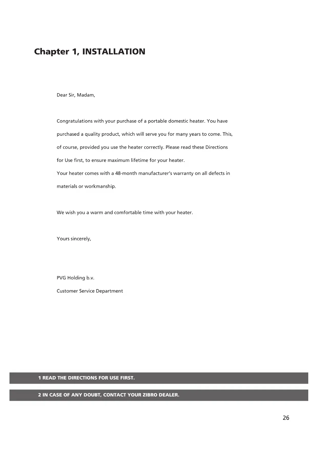
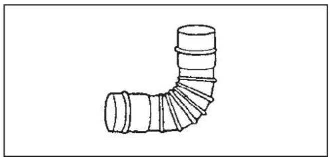
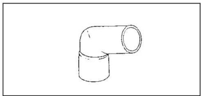
Technical illustration of a mechanical assembly with three views: two screws, one threaded bolt, and one cylindrical component (no text or symbols)Exhaust pipe (1) Right-angled exhaust pipe bend (1)
natural_image
Line drawing of a U-shaped pipe fitting with layered cylindrical components (no text or symbols)Chapter 1, INSTALLATION
natural_image
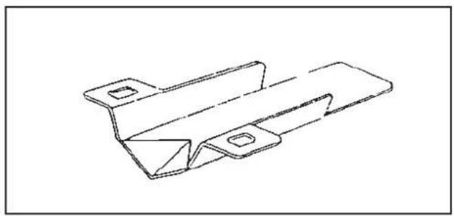
Technical line drawing of a metal bracket component (no text or symbols)Discharge chute (1) Right-angled air hose (2)
natural_image
Line drawing of a 10-inch pipe fitting (no text or symbols)
natural_image
Simple line drawing of a mechanical clamp or bracket with a circular ring and fastener (no text or symbols)
natural_image
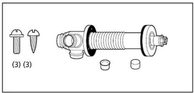
Simple line drawing of a coiled spring (no text or symbols)Flexible air hose (1) Hose clip (2)
Chapter 1, INSTALLATION
- For the standard installation, use the template supplied to position the hole for the exhaust pipe correct-
ly. Use cellotape or small nails to attach the template to the desired position on the wall (see Fig. 4).
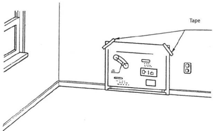
Fig. 4
Comment: The heater must be installed on a strong and stable floor. The floor must be flat and level. If this is not the case, the heater can be levelled by means of adjustable legs. This can be checked with the plumb line.
- Drill the hole for the exhaust pipe. Use a hole saw with a diameter of 70\~80 mm (see Fig. 5). The opening on the interior side of the wall must be a little higher than the opening on the outside in order to create a slight gradient in the feed-through and exhaust pipe
after installation (approximately 2°) (see Fig. 6). This ensures that condensed water in the exhaust pipe flows to the outside and prevents the penetration of rainwater and snow after installation.
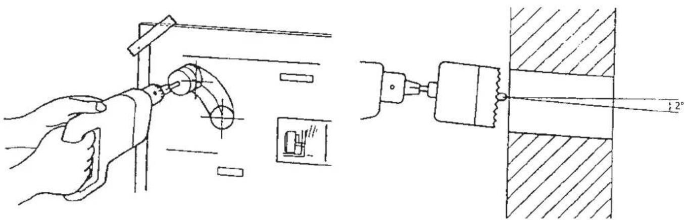
Fig. 5 Fig. 6
Chapter 1, INSTALLATION
3. Install the inner flue pipe.
a. For wall thickness 230\~320mm.
From inside the room, insert the inner flue pipe through the hole. Make sure the arrow on the inner flue pipe is pointing up. Secure the inner flue pipe to the wall with the three wood screws. (See Fig. 7)
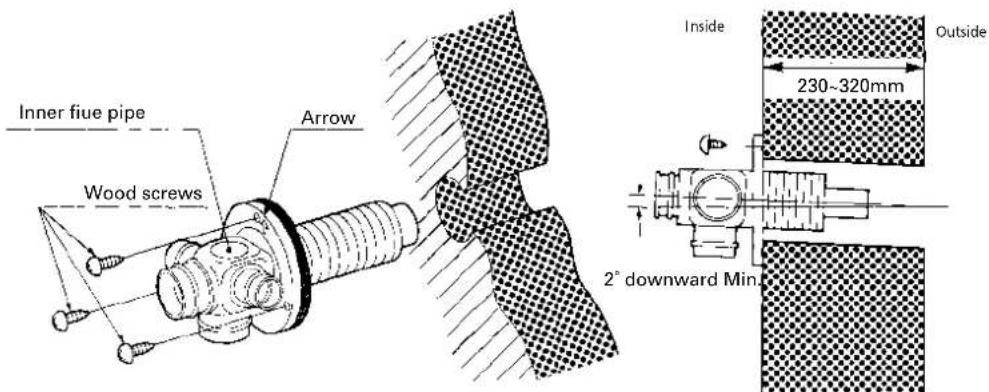
Fig. 7
b. For wall thickness 130\~230mm.
Remove Intake joint and Exhaust joint from Outer flue pipe (See Fig. 8).
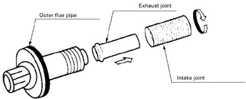
Fig. 8
Chapter 1, INSTALLATION
c. From outside, insert the outer flue pipe through the hole. Secure the outer flue pipe to the wall by turning it clockwise. This locks the two halves together (See Fig. 9).
IMPORTANT: Make sure the arrow on the outer flue pipe frange is pointing up. Make sure to secure the outer flue pipe well. (A-part shown in Fig. 9)
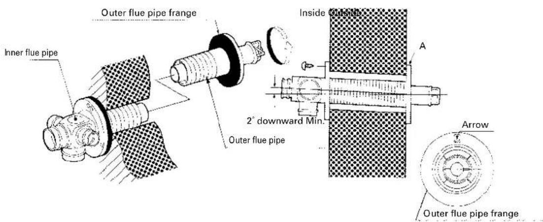
Fig. 9
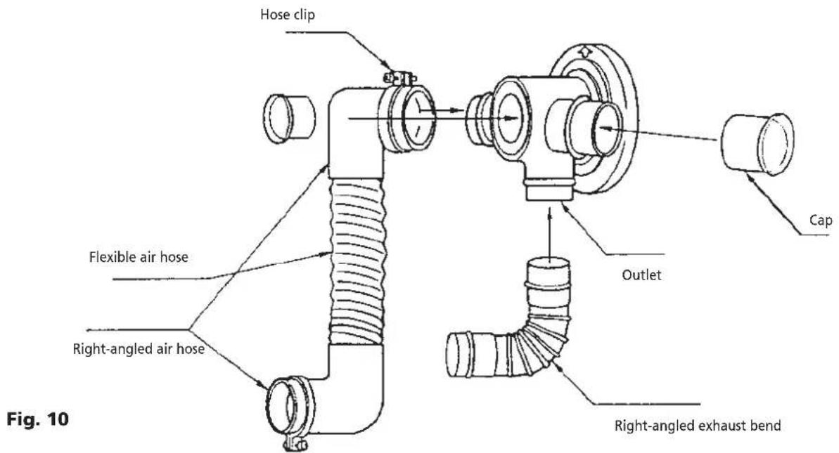
- Attach the right-angled exhaust pipe bend to the outlet of the exhaust pipe. Cut, if necessary, the flexible air hose to size. Fasten the right-angled air hose to both ends of the flexible air hose – now attach the right-angled air hose to the inlet of the exhaust pipe. Attach the right-angled air hose to both ends of the flexible air hose. Now fasten the right-angled air hose to the inlet of the exhaust pipe.
Fasten the right-angled air hose onto the inlet with a hose clip. Seal the inlets and outlets that are not being used with the caps supplied. Check that the caps are firmly in position (See Fig.10). Use water or soap suds to provide lubrication when fitting the right-angled air hose onto the flexible air hose. The total length of the exhaust pipe may be a maximum of 3 m (max. 3 bends).
Chapter 1, INSTALLATION
- Place the heater in the desired location. Attach the right-angled exhaust bend to the outlet (the top open-
ing) and attach the right-angled air hose to the inlet. Check that everything is firmly attached (See Fig. 11).
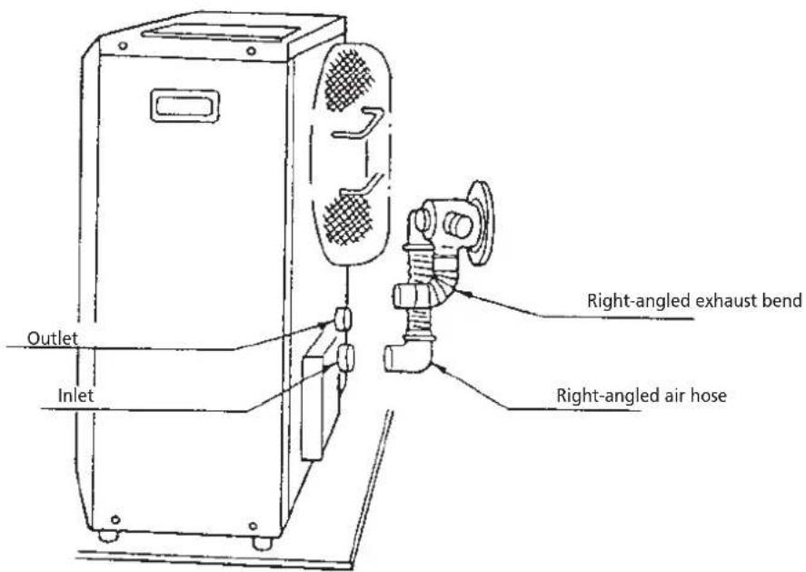
Fig. 11
- Fasten the right-angled air hose to the inlet with the hose clip. Attach the right-angled exhaust bend to the exhaust pipe with the pipe holder (attach the pipe holder to the connection of the right-angled exhaust
bend). Attach the right-angled exhaust bend to the outlet by sliding the pipe lock into the outlet clip (See Fig. 12).
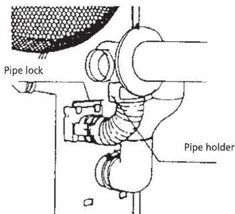
Fig. 12
- Installation of an external fuel tank The installation of an external fuel tank is illustrated in a diagram (Fig. 1-11). The fact that installation techniques for fuel tanks vary means that it is impossible to
provide a specific installation procedure. However, certain criteria determine the manner in which the heater is supplied with fuel. Use the following checklist as a guideline for the installation of an external tank.
Chapter 1, INSTALLATION
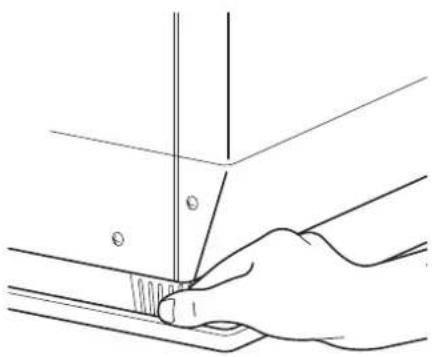
- Make sure the position of the heater is level by using the plumb bob located at the right side of the heater. The plumb bob weight should be within the circle. If
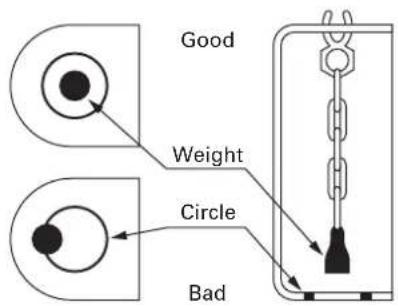
Plumb bob as viewed from above
Fig. 13
- A room temperature sensor is provided with a 2.5 m long extension wire. It is located on the rear of the cabinet. Make sure that the extension wire is not touching the exhaust pipe. The room temperature sensor can be installed either with the self adhesive tape on the back or with a wood screw provided with the sensor dependthe plumb bob weight is not within the circle, adjust the heater legs until the plumb bob weight is within the red circle (See Fig. 13 & 14).
natural_image
Line drawing of a hand holding a thin object with a ruler above, no text or symbols presentFig. 14
ing on the type of surface chosen for installation.

NOTE: Choose a location for the sensor that is not in the path of direct sunlight, drafts or the flow of warm air from the heater.
(a) Self Adhesive Tape
Peel off the protective tape on the back of the sensor and expose the adhesives. Place the sensor on the desired location on the wall and press down.
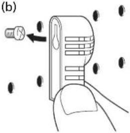
(b) Wood Screw
Screw down the wood screw provided with the heater into the desired location on the wall. Hook the back of the room temperature sensor.
-
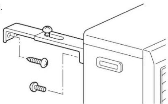
After installation is completed, secure heater to the wall with the wall brackets provided with the heater. Make sure the heater is parallel to the wall (See Fig. 15).
-
Before ignition, recheck the following:
a. All connections are tight and firm.
b. The heater and the flue pipe areas are free of any materials.
c. The heater is level and parallel to the wall.
(a)
natural_image
Line drawing of a hand holding a small electronic device with a handle and cable (no text or symbols)(b)


natural_image
Technical line drawing of a mechanical bracket with two screws inserted (no text or symbols)Fig. 15
Chapter 1, INSTALLATION
CHECKLIST
- Check whether the heater has been connected to a suitable socket.
- Check that a suitable quantity of petroleum is in the fuel tank.
- Ensure that the fuel is free of water or other contaminants.
- Check that the fuel tank is in good working order – it must be free of rust, corrosion and/or leaks.
- Inspect the fuel pipe for signs of leaks, loose connections, cracks, air bubbles or blockages.
- Check that the fuel valves on the fuel tank and the fire safety valve are open in order to allow the free flow of fuel.
- Check outside the building in order to ascertain that there is no fuel or obstructions to the free circulation of air in the area immediately adjacent to the exhaust pipe.
- Inspect the inlet air hose for cracks, loose connections or blockages.
- Check the outlet air hose for cracks, loose connections or blockages.
- Check the back of the heater to ensure that the airflow to the air circulation ventilator is not obstructed.
- Inspect the interior of the building to ensure that the area immediately adjacent to the heater is free of fuel and objects that may obstruct the free flow of air.
- Check that the room sensor is not exposed to draughts, direct sunlight or heat radiated directly from the heater.
- Use a spirit level to check that the heater is level.
If this inspection brings any faults to light, resolve these problems before using the heater.

Use only water-free high quality pure paraffin oil. Never use gasoline, LPG, camping gas or other flammable liquids. The use of these substances may cause explosions or fire.
Available fuel supply options
The fuel supply of the Laser 95 can be set up as follows:
Large gravity-operated exterior tank
To install a large gravity-operated exterior tank, follow the instructions below. We recommend that you call in a recognised installer.
The inlet pressure to the heater may not exceed 2.5 psi. Use a pressure reduction valve with a maximum thrust of 2.5 psi ( ± 0.17 bar).
The installation height of the bottom of the fuel tank must be 40 cm or more above the level of the floor on which the heater is standing. This will ensure that there is sufficient fuel inlet pressure. The distance between the floor surface on which the heater is standing and the top of the fuel tank may not exceed 2.5 metres. This will prevent excessive fuel inlet pressures.
The pipe may not have any inverted U-bends (to prevent air pockets that may block the fuel supply).
We recommend using a water-blocking filter in the fuel pipe leading into the tank. A cut-off valve must be fitted to the tank.
We recommend installing a fire safety valve and a fuel filter in the fuel pipe.
The use of a cut-off valve, placed just before the pipe enters the building, will limit the quantity of fuel to be tapped off to a minimum if the heater requires maintenance.
Chapter 1, INSTALLATION
If a fuel pipe inside the building is more than 90 cm long, you must use an extra cut-off valve.
The external fuel tank must be placed at least 2 metres away from any heat source.
The external fuel tank must have a filling opening on the top and a ventilation opening with a weather-resistant cap on the side. Some tanks use the same opening for ventilation and filling.
Important: Ensure that the fuel pipe is free of dust and waste particles. These particles may cause problems in the fuel receptacle.
Copper tubing with an exterior diameter of 3/8" must be used for the fuel pipe.
The external tank and the installation of the external tank must meet fire applicable (local) regulations. Refer to the local authorities for these regulations.
Installation may be done by a qualified person only.
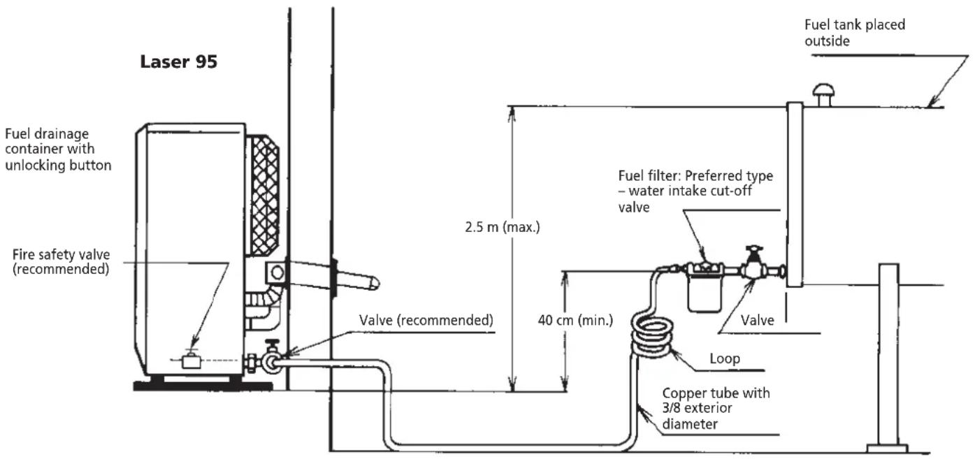
Fig.1-11 Connection to the fuel pipe
The Laser 95 is an easy to use vented petroleum heater. It provides considerable quantities of heat, automatically regulates the room temperature, uses very little fuel and electricity and has options for automatic or manual operation.
This chapter provides all the information required for the operation of the Laser heater system. All specified operating procedures must be carried out in the order in which they are described.
2. Laser FF 95 heater specifications
Low Medium High
Heat yield (W) 3.100 6.300 9.500
Fuel consumption (l/h) 0.38 0.73 1.080
Fuel consumption (g/h) 304 584 864
- Nominal yield
(as applied to petroleum heaters): \~92%
• Power consumption:
Ignition Burning
280 W 80 W
Ventilator capacity: 2.9/1.9/0.8 cubic metre/min.
- Fuel source: external tank
- Room volume indication when used as main heating source: 130 - 440m ^3
3. Operating elements and lights
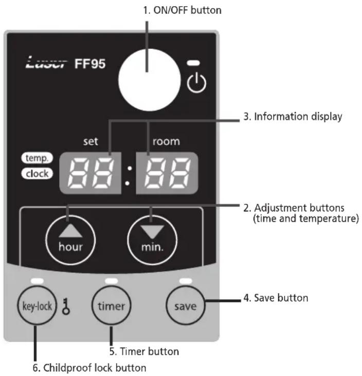
Fig. 2-1 Operation panel
1. ON/OFF button:
The main switch to turn the heater on and off. Switch it "ON" to activate the heater. Combustion will start after a 3-9 minutes pre-heating period. The heater has 4 settings "HIGH", "MEDIUM", "LOW" and "OFF".
2. Adjustment buttons:
Temperature selection switches offer the user the option to select the desired temperature during operation.
3. Information display
Displays the clock, set temperature, room temperature and error codes.
4. SAVE button:
Allows you to limit the temperature.
When this function is activated, the heater will automatically switch off and on again.
5. TIMER button:
Allows you to switch on the heater automatically at a preset time.
6. CHILDPROOF LOCK button:
Can be used to prevent children accidentally changing the heater settings.
Step 1: Open the valve(s)
Screw the valve on the top of the removable tank open or open the valve for the external fuel tank and the fire safety valve of the heater (if present).
Step 2: Start the fuel supply
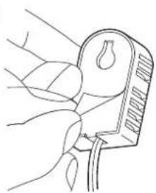
Carefully press the red unlocking button for one second to release the float in the fuel receptacle.
The fuel receptacle only has to be unlocked when the heater is activated for the first time or after it has run out of fuel, or if the heater has not been used for an extended period of time. Unlocking may also be required if the fuel inlet pressure exceeds 2.5 psi ( ± 0.17 bar). In this case, a pressure reduction valve must be installed.
Step 3: Adjust the clock
Important: The clock on the heater must always be set to the correct time.
A. Switch the time selector switch to "CLOCK SET"
B. Press the "HOUR" and the "MINUTE" buttons to adjust the hours and minutes. Pressing the "HOUR" or "MINUTE" button once will adjust the time by one unit (hours or minutes respectively). Holding the button down accelerates the adjustment of the time display.
All clock and timer settings are deleted if the power is cut off for a period longer than 10 seconds. The information display flashes "PM 12:00" when the heater is switched off. The clock and timer now have to be reprogrammed.
C. Set the timer switch to the "NORMAL" setting after completing the clock adjustment. The current time is then displayed on the digital indicator.
5. Igniting the heater
The heater is operated directly by the user. However, the heat yield is controlled automatically in accordance with the room temperature registered by the temperature sensor.
Step 1: Switch the heater ON
Press the ON/OFF button. The current room temperature and the set temperature are displayed on the information display.
The ON/OFF light starts to flash, after which the heater will switch on.
Note: (*) The start-up time depends on the room temperature.
After 9-15 minutes, the heater will automatically select the correct operating mode and the ON/OFF button will now be illuminated continuously.
Room temperature:
under 0°C 11 minutes
0°C - 15°C 9 minutes
15°C 8.5 minutes
If no flames are visible after the start-up period, the heater will deactivate and then restart automatically. If flames are still not detected, the heater will deactivate and will have to be restarted manually (error code E-2 on the information display).
Step 2: Setting the room temperature
The temperature setting can only be adjusted, when the heater is burning. Use the adjustment buttons to adjust the temperature. First press either of the two buttons to switch on the function (the TEMP light next to the information display will start blinking). Next, adjust the temperature using the button on the right (▼min.) to set the temperature to a higher setting and the button on the left (▲hour) to lower the temperature. Press once to increase the value one step. After approximately 10 seconds the light will stop blinking and setting will be locked. The available temperature settings range from 10°C minimum to 32°C maximum. When the heater has been unplugged (or after a power failure), the temperature will reset to the factory setting of 20°C.
The operating mode is automatically controlled in accordance with the room temperature detected by the room temperature sensor. The heater works in the "HIGH" operating mode until the room temperature has reached the desired level.
When the room temperature reaches the chosen setting, the heater automatically switches to the "MED" or "LOW" operating mode in order to maintain the desired temperature.
Step 3: The correct use of 'SAVE'
The 'SAVE' function allows you to limit the temperature. When this function is activated, the heater will automatically switch off, when the room temperature exceeds the set temperature by 2°C. Subsequently, when the room temperature has dropped again to the set temperature, the heater will automatically switch on again. Activate the 'SAVE' setting by pressing the appropriate button. The SAVE indicator light will light up. Switch off the function by pressing the SAVE button once again.

Without the 'SAVE' setting your heater will maintain the set temperature by approximation as well, by adjusting its heating capacity. 'SAVE' is an economy setting, which you can use when, for instance, you are not present in the room or to keep it frost-free.
Step 4: The 'FUEL' indicator light
When the FUEL indicator light lights up, it means that there is only fuel left for 10 more minutes. The count-down of the remaining heating time can be seen in the information display. You remove the fuel tank and refill it outside the living room. If you don't refill it, you will hear an alarm signal every two minutes, warning you to refill the removable tank and after 10 minutes the heater will switch off automatically.
6. Timer operation
The timer allows you to switch on the heater automatically at a preset time.
In order to switch on the timer, the correct time must have been set and the heater should be off. Follow the procedure below:
[1] Press the TIMER button. The TIMER light and the information display will start blinking.
[2] Use the adjustment buttons to set the time at which the heater must ignite. Use the button on the left (▲hour) to set the hours and the button on the right (▼min.) to set the minutes (interval of 10 minutes).
[3] Press the ON/OFF button while the information display is blinking.
[4] After approximately 10 seconds the information dis-
play will show CLOCK again and the TIMER indicator light will light up, indicating that the timer function has been activated.
To clear the timer setting, press the ON/OFF button once.

Note: When the room temperature is less than 15^ C, the preset time is changed automatically depending on the room temperature in order to heat the room by the desired time.
Room temperature Ignition time
More than 15°C Set time
0°C \~ 15°C 10 minutes before set time
Less than 0°C 20 minutes before set time
7. Room temperature sensor
The room temperature sensor is fitted with a 2.5 meter cable. This is located on the back of the heater. Ensure that the cable does not touch the outlet tube. The room temperature sensor can be installed with cello tape or with a wood screw.
Select the location where the sensor is to be installed in such a way that it will not be exposed to direct sunlight, draughts or the warm air flowing out of the heater.
8. Childproof lock
The childproof lock can be used to prevent children accidentally changing the heater settings. When the heater is burning and the childproof lock is on, the heater can only be switched off. Other functions are blocked then. If the heater has already been switched off, the childproof lock also prevents accidental ignition of the heater. Activate the childproof lock by pressing the appropriate button and holding it down for more than 3 seconds. The KEY-LOCK indicator light will light up, indicating that the childproof lock has been activated. Switch off the childproof lock by pressing the button and holding it down for more than 3 seconds once again.
9. Switching off the heater
There are two ways to switch off the heater.
[1] Press the ON/OFF button. The information display
will show the CLOCK signal. The air circulation ventilator and the ventilator motor continue to operate for approximately 3 minutes in order to cool the heater down.
[2] Press the TIMER button, when you want to switch off the heater and ignite it again with the timer the next time. This not only switches off the heater, but it also activates the timer function. You can change the required time with the adjustment buttons.
10. Recovery after overheating
The heater is protected against damage caused by overheating.
A sensor will activate if the temperature in the housing exceeds 90^ C.
Step 1: Switch the heater OFF.
Step 2: Allow the heater to cool down.

Ensure that the metal housing has cooled sufficiently before touching it.
Under normal conditions, a period of 30 to 45 minutes is sufficient to allow the heater to cool down completely.
Step 3: Pull the heater plug out of the socket.
Step 4: Look for the source of the overheating.
Overheating is usually caused by objects that obstruct the free flow of air. Check that the circulation ventilator or exhaust pipes are not blocked. Check that there are no objects blocking the outlet system.
Step 5: Remove the front panel.
Step 6: Clean the inside of the heater.

Before starting to clean the heater, ensure that the interior is cool enough to touch. Wipe all dust off the outside of the housing with a clean, non-fluffy, damp cloth or another suitable cleaning aid. Do not forget to clean the outside of the heat chamber and the heat exchanger.
Step 7: Re-attach the front panel.
Step 8: Insert the heater plug into the socket.
Step 9: Switch the heater ON.
Step 10: Re-program the heater (clock and timer).

If the heater overheats after the completion of a recovery procedure, contact your dealer and do not switch the heater on until the problem has been resolved.
11. Cleaning the filter (monthly)
Switch off the heater and let it cool down, before you start any maintenance work. Also disconnect the plug from the mains.
Your Zibro needs hardly any maintenance. It is, however, important that you clean the louvers, grilles and circulation fan cover on the back of the heater weekly. Periodically check the flue pipe connection for leakage or separation.
Regularly inspect the fuel filter as well:
[1] Remove the removable tank from the heater and remove the fuel filter. Some drops may leak from the filter; keep a cloth at hand.
[2] Remove the dirt by tapping the fuel filter upside-down against a hard surface. (Never clean it with water!)
[3] Reinstall the fuel filter into the heater.
We recommend that you remove dust and stains in time with a damp cloth, because otherwise these may cause stains that are hard to remove.

Do not remove any heater components yourself. Always contact your Zibro dealer for repairs. When the power cord is damaged, it may only be replaced by an authorized fitter. Use a new cord of the type H05 VV-F.
12. Before consulting an expert
The following situations do not indicate defects.
While switching the heater on or off.
White smoke can be seen when the heater is switched on for the first time.
Machine oil or dust on the burner chamber or heat exchanger is burning.
The flames flicker for several minutes after the heater has
The ignition rod continues to function when the heater is cold, even several minutes after ignition. This may cause the flames to be a little larger.
The heater makes intermittent creaking sounds when warming up or cooling down.
Expansion and shrinkage of metal parts may cause a slight creaking sound.
Circulation of air in the room does not start immediately when the heater is lit.
To prevent unpleasant cold draughts, the ventilator only switches on when the heater has become warm.
A loud clicking sound can be heard during the first use or when the fuel runs out.
There is air in the fuel pump. This should be gone within approximately 1 minute.
Note: The fuel pump may make a slight ticking sound during normal operation. This does not indicate a problem.
While the heater is in operation
A part of the burner pot and/or heat exchanger becomes red in color during operation.
This is normal and does not indicate a problem.
Chapter 3, ERROR MESSAGES
ERROR CODE INFORMATION WHAT TO DO
E-0 Power interrupted. Re-ignite the heater
E-2 Ignition safety feature is activated. Contact your dealer
E-6 Extinguished during operation. Contact your dealer
E-8 Blower motor malfunction. Contact your dealer
E-12 Overheating safety feature is activated. Clean the air filter and
remove dust.
E-13 Burner thermistor malfunction Contact your dealer
Excess fuel in the burner Contact your dealer
E-22 Ignition failure three times Contact your dealer
-- : -- No fuel. Refill removable tank.
| Timer is not setting. | Set the timer. | |
| Hi | Room temperature is higher than 35°C. | Check the position of room temperature sensor. |
| Position of room temperature sensor is not correct. | ||
| Lo | Room temperature is lower than -10°C. Room thermistor malfunction or disconnected. | Check the position of room temperature sensor. |
Chapter 4, WARRANTY PROVISIONS
Your heater comes with a 48-months warranty starting on the date of purchase. Within this period all defects in material or workmanship will be repaired without any charge. The following provisions shall apply regarding this warranty:
Waste electrical products should not be disposed with household waste. Please recycle where facilities exist. Check with your local authority or retailer for recycling advice.
1 We expressly dismiss all other claims for damages, including consequential damages.
2 Any repairs or replacements of components within the term of warranty will not result in an extension of the term of warranty.
3 The warranty shall no longer apply, when the heater has been modified, non-original parts have been used, or when it is repaired by third parties.
4 The warranty shall not apply to parts that are subject to normal wear, such as the burner mat and the manual fuel pump.
5 The warranty shall only apply, when you present the original, dated proof of purchase, provided no changes have been made to it.
6 The warranty shall not apply to damages caused by actions not in compliance with the Directions for Use, neglect, and the use of an incorrect type of fuel, or fuel past its use-by date. The use of incorret fuel can even be dangerous*.
7 Transportation costs and the risks involved during the transportation of the heater or heater components shall always be for the account of the purchaser.
In order to avoid unnecessary costs, we recommend that you always read the 'Directions for Use' carefully first. In case they offer no solution, please take the heater to your dealer for repair.
* Highly inflammable substances may induce uncontrollable burning, causing flames to break out. Should this happen, never try to move the heater, but always switch off the heater immediately. In case of emergency you may use a fire extinguisher, but only a type B extinguisher: a carbon dioxide or powder extinguisher.
WAT U VOORAF MOET WETEN
DE JUISTE BRANDSTOF
natural_image
Technical line drawing of a mechanical assembly with no visible text or symbolsnatural_image
Technical line drawing of a rectangular electronic component with mounting holes and a central slot (no text or symbols)natural_image
Technical line drawings of four different metal bracket components: two rectangular plates with holes, a threaded screw, and a conical screw (no text or symbols present)
natural_image
Simple line drawing of a rectangular arch structure with two side panels (no text or symbols)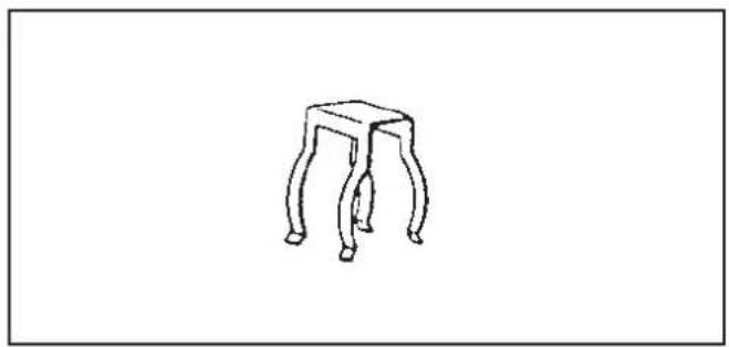
natural_image
Simple line drawing of a four-legged stool (no text or symbols)natural_image
Line drawing of a U-shaped pipe fitting with layered segments (no text or symbols)
natural_image
Technical illustration of a mechanical assembly with three views: two screws, one threaded component, and one cylindrical part (no text or symbols)natural_image
Technical line drawing of a metal bracket component (no text or symbols)natural_image
Line drawing of a 10-inch pipe fitting (no text or symbols)
natural_image
Simple line drawing of a coiled spring (no text or symbols)Flexi-luchtslang (1) Slangklem (2)
natural_image
Simple line drawing of a mechanical clamp or bracket with a circular ring and fastener (no text or symbols)Fig. 5 Fig. 6
natural_image
Line drawing of a hand holding a tool with a ruler, no text or symbols presentFig. 14
Fig. 13
natural_image
Line drawing of a hand holding a small electronic device with a handle and cable (no text or symbols)(b)
natural_image
Technical line drawing of a door handle assembly with screws and screw holes (no text or symbols)Fig. 15
FOUT CODE INFORMATIE OPLOSSING
Distributed in Europe by PVG Holding B.V.
Benötigen Sie weitere Informationen oder treten Probleme auf, besuchen Sie bitte unsere Website www.zibro.com, oder setzen Sie sich mit unserem Kundendienst in Verbindung (Telefonnummer auf www.zibro.com).
For alle yderligere oplysninger eller ved eventuelle problemer med apparatet henvises til www.zibro.com eller det lokale Kundecenter (telefonnumre findes i www.zibro.com).
Si necesita información o si tiene algún problema, visite nuestra página Web www.zibro.com, o póngase en contacto con el servicio cliente (hallará el número de teléfono en www.zibro.com).
(F) Si vous souhaitez obtenir des informations supplémentaires ou si vous rencontrez un problème, rendez-vous sur notre site Web (www.zibro.com) ou contactez le notre service client (vous trouverez l'adresse et numéro de téléphone sur www.zibro.com).
FHN Jos haluat huoltoapua, lisätietoja tai laitteen kanssa tulee ongelmia, tutustu verkkosivustoon osoitteessa www.zibro.com tai kysy neuvoa PVG kuluttajapalvelukeskuksesta (www.zibro.com).
If you need information or if you have a problem, please visit the our website (www.zibro.com) or contact our sales support (you find its phone number on www.zibro.com)
① Per informazioni e in caso di problemi, visitate il sito Web www.zibro.com oppure contattate il Centro Assistenza Clienti (per conoscere il numero di telefono, consultate www.zibro.com).
Hvis du trenger informasjon, eller hvis du har et problem med produktet, kan du gå til nettsidene www.zibro.com. Alternativt kan du kontakte med PVG' forbrukertjeneste (telefonnummeret i www.zibro.com).
NL Als u informatie nodig hebt of als u een probleem hebt, bezoek dan de onze website (www.zibro.com) of neem contact op met de afdeling sales support (adres en telefoon op www.zibro.com).
Se necessitar de informações ou se tiver problemas, visite o Web site www.zibro.com ou contacte o Centro de Assistência (número de telefone o www.zibro.com)
PL W przypadku problemów i w celu uzyskania szczegółowych informacji odwiedź stronę internetową Zibro dostępną pod adresem www.zibro.com lub skontaktuj się z Centrum kontaktów Zibro (www.zibro.com)
⑧ Om du behöver service eller information eller har problem med apparaten kan du besöka www.zibro.com eller kontakta Zibro kundtjänst (du hittar telefonnumret på www.zibro.com).
Če želite dodatne informacije, obiščite spletno mesto podjetja na naslovu www.zibro.com ali pokličite na telefonsko (www.zibro.com).
Daha fazla bilgiye ihtiyaç duyarsanız veya bir sorunla karşılaşırsanız, www.zibro.com adresindeki Zibro Internet sitesini ziyaret edin veya ülkenizde bulunan Zibro müşteri merkeziyle iletişim kurun (telefon numarasını: www.zibro.com).
Zibro® is registered trademark of TOYOTOMI Co., Ltd. for paraffi n heaters.
ZIBRO brand paraffi n heaters are made in Japan and imported by PVG Holding B.V.


- Chapter 1, INSTALLATION
- WHAT YOU NEED TO KNOW IN ADVANCE
- THE RIGHT FUEL
- TIPS FOR SAFE USE
- Introduction
- Moving the heater
- Recommended tool kit
- The electrical supply system
- Fuel tank
- Wiring for the room temperature sensor
- Unpacking
- Standard installation parts
- Install the inner flue pipe.
- CHECKLIST
- Available fuel supply options
- Large gravity-operated exterior tank
- Laser FF 95 heater specifications
- Operating elements and lights
- ON/OFF button:
- Adjustment buttons:
- Information display
- SAVE button:
- TIMER button:
- CHILDPROOF LOCK button:
- Igniting the heater
- Timer operation
- Room temperature sensor
- Childproof lock
- Switching off the heater
- Recovery after overheating
- Cleaning the filter (monthly)
- Before consulting an expert
- Chapter 3, ERROR MESSAGES
- ERROR CODE INFORMATION WHAT TO DO
- Chapter 4, WARRANTY PROVISIONS
- WAT U VOORAF MOET WETEN
- DE JUISTE BRANDSTOF
- Distributed in Europe by PVG Holding B.V.
Brand : ZIBRO
Model : Laser FF 95
Category : Heating