
IKE96654FB - Cooker AEG - Free user manual and instructions
Find the device manual for free IKE96654FB AEG in PDF.
| Technical specifications | Built-in cooker, convection oven, 90 cm wide |
|---|---|
| Cooking type | Induction |
| Number of burners | 4 induction burners |
| Oven capacity | 70 liters |
| Energy | Electric |
| Oven features | Fan oven, grill, convection cooking |
| Dimensions (W x H x D) | 90 x 85 x 60 cm |
| Weight | 75 kg |
| Usage | Touch controls, digital display, built-in timer |
| Maintenance | Easy cleaning thanks to glass surface and enamelled interior |
| Safety | Overheat protection, child safety lock |
| Energy consumption | Energy class A |
| Included accessories | Grill rack, roasting pan, user manual |
| Warranty | 2 years |
Frequently Asked Questions - IKE96654FB AEG
User questions about IKE96654FB AEG
0 question about this device. Answer the ones you know or ask your own.
Ask a new question about this device
Download the instructions for your Cooker in PDF format for free! Find your manual IKE96654FB - AEG and take your electronic device back in hand. On this page are published all the documents necessary for the use of your device. IKE96654FB by AEG.
USER MANUAL IKE96654FB AEG
natural_image
Four simple gray circles arranged in a 2x2 grid within a square frame (no text or symbols)PËR REZULTATE PERFEKTE
How to install your AEG Induction Hob - Worktop installation

4. PËRSHKRIM I PRODUKTIT
text_image
Safety warning illustration showing a cooking pot with warning symbol and three safety symbols: crossed-out, no warning, and cooking pan.text_image
Diagram showing a device with labeled buttons and a speech bubble containing numeric values 0, 1, 2.natural_image
Two schematic diagrams showing a belt drive system with two pulleys and a central cylinder, each marked with checkmarks (no text or symbols present)
text_image
Two safety warning symbols: crossed-out cross symbol and triangular warning triangle with exclamation marknatural_image
Pure diagram of three identical rectangular frames with vertical double-headed arrows, no text or symbols present.natural_image
Diagram of a smart heating or monitoring system with a pot, antenna, and wireless signal icon (no text labels)
How to install your AEG Induction Hob - Worktop installation
4. ОПИСАНИЕ НА УРЕДА
text_image
Safety warning illustration showing cooking process with a pot, warning symbol, and crossed-out safety symbols.text_image
Diagram showing a speech bubble with numbered indicators and a ruler, likely illustrating a measurement or calibration system.natural_image
Two schematic diagrams showing a belt drive system with two pulleys and a central cylinder, each with checkmark indicators (no text or labels)
text_image
Two warning symbols with crosshairs and triangular warning indicators, one containing a circular symbol with 'R' and an exclamation mark.natural_image
Pure diagram of three identical vertical arrows within rectangular frames, no text or symbols present6. ПРЕПОРЬКИ И СЪВЕТИ

ВНИМАНИЕ!
natural_image
Diagram of a smart air lift or control system with a tank, sensor, and signal icon (no text labels)
| How to install your AEG Induction Hob - Worktop installation |
4. OPIS PROIZVODA
4.1 Izgled površine za kuhanje
flowchart
graph TD
    A["1"] --> B["Process Step 1"]
    B --> C["Process Step 2"]
    C --> D["Decision/Branch Path"]
    D --> E["1"]
    D --> F["2"]
5. SVAKODNEVNA UPORABA

UPOZORENJE!
text_image
Safety warning illustration showing cooking process with warning triangle and cross symbolPosuđe stavite na sredinu odabrane zone.
Indukcijske polja za kuhanje automatski se prilagođavaju dimenzijama dna posuđa. Kada posuđe za kuhanje stavite u ispravan položaj, ploča za kuhanje ga prepoznaje i uključuje se odgovarajuća upravljačka traka. Iznad upravljačke trake pojavljuje se crveni pokazatelj zone kuhanja koji označava položaj lonca.

text_image
Diagram showing a device interface with labeled buttons and a speech bubble containing binary code (0, 1, 2)natural_image
Two schematic diagrams showing a vertical structure with circular elements and directional arrows, no text or symbols present.
text_image
Safety warning symbols for electrical hazard, showing crossed warning signs and triangular warning symbols with exclamation marks.natural_image
Diagram of a smart heating or monitoring system with a pot, antenna, and wireless signal icon (no text labels)
How to install your AEG Induction Hob - Worktop installation

4. POPIS SPOTŘEBIČE
text_image
Safety warning illustration showing a cooking pot with warning symbol and three safety symbols: crossed-out, no cross, and open with a pipe.text_image
Diagram showing a device with labeled buttons and a speech bubble containing numeric values 0, 1, 2.natural_image
Two schematic diagrams showing mechanical or electrical components with circular elements and directional arrows, no text or symbols present.
text_image
Two safety warning symbols: crossed cross symbol and triangular warning triangle, both with exclamation marks.natural_image
Pure diagram of three identical rectangular frames with vertical double-headed arrows, no text or symbols present.6. TIPY A RADY

VAROVÁNÍ!
natural_image
Diagram of a smart air lift or control system with a tank, sensor, and signal icon (no text labels)
text_image
How to install your AEG Induction Hob - Worktop installation4. PRODUKTBESKRIVELSE
text_image
Safety warning illustration showing cooking process with warning symbol and three safety symbols: no cross, allowed, and checked.text_image
Diagram showing a device with a speech bubble containing icons and numerical labels, likely illustrating a measurement or status.natural_image
Two schematic diagrams showing a pulley system with two wheels and a central cylinder, each with checkmark indicators (no text or symbols)
text_image
Two safety warning symbols: crossed-out cross symbol and circular warning symbol with exclamation marknatural_image
Pure diagram of three identical vertical arrows within rectangular frames, no text or symbols present6.1 Kogegrej

6.2 Lyden under drift
Hvis du kan høre:
6.3 Öko Timer (Eco-timer)
natural_image
Diagram of a cooking setup with a pot, ladder, and Wi-Fi signal (no text or symbols)
Thank you for choosing this AEG product. We have created it to give you impeccable performance for many years, with innovative technologies that help make life simpler – features you might not find on ordinary appliances. Please spend a few minutes reading to get the very best from it.
Visit our website to:

Get usage advice, brochures, trouble shooter, service and repair information: www.aeg.com/support

Register your product for better service: www.registeraeg.com

Buy Accessories, Consumables and Original spare parts for your appliance: www.aeg.com/shop
CUSTOMER CARE AND SERVICE
Always use original spare parts.
When contacting our Authorised Service Centre, ensure that you have the following data available: Model, PNC, Serial Number.
The information can be found on the rating plate.

Warning / Caution-Safety information

General information and tips

Environmental information
Subject to change without notice.
CONTENTS
- SAFETY INFORMATION...... 102
- SAFETY INSTRUCTIONS.... 104
- INSTALLATION....107
- PRODUCT DESCRIPTION....108
- DAILY USE....109
- HINTS AND TIPS....114
- CARE AND CLEANING.... 117
- TROUBLESHOOTING....117
- TECHNICAL DATA.... 119
- ENERGY EFFICIENCY....119
- ENVIRONMENTAL CONCERNS....120
1. ⚠SAFETY INFORMATION
Before the installation and use of the appliance, carefully read the supplied instructions. The manufacturer is not responsible for any injuries or damage that are the result of incorrect
installation or usage. Always keep the instructions in a safe and accessible location for future reference.
1.1 Children and vulnerable people safety
- This appliance can be used by children aged from 8 years and above and persons with reduced physical, sensory or mental capabilities or lack of experience and knowledge if they have been given supervision or instruction concerning the use of the appliance in a safe way and understand the hazards involved. Children of less than 8 years of age and persons with very extensive and complex disabilities shall be kept away from the appliance unless continuously supervised.
- Children should be supervised to ensure that they do not play with the appliance.
- Keep all packaging away from children and dispose of it appropriately.
- WARNING: Keep children and pets away from the appliance when it operates or when it cools down. Accessible parts become hot during use.
- If the appliance has a child safety device, it should be activated.
- Children shall not carry out cleaning and user maintenance of the appliance without supervision.
1.2 General Safety
- WARNING: The appliance and its accessible parts become hot during use. Care should be taken to avoid touching heating elements.
- WARNING: Unattended cooking on a hob with fat or oil can be dangerous and may result in fire.
- NEVER try to extinguish a fire with water, but switch off the appliance and then cover flame e.g. with a lid or a fire blanket.
-
WARNING: The appliance must not be supplied through an external switching device, such as a timer, or connected to a circuit that is regularly switched on and off by a utility.
-
CAUTION: The cooking process has to be supervised. A short term cooking process has to be supervised continuously.
- WARNING: Danger of fire: Do not store items on the cooking surfaces.
- Metallic objects such as knives, forks, spoons and lids should not be placed on the hob surface since they can get hot.
- Do not use the appliance before installing it in the built-in structure.
- Do not use a steam cleaner to clean the appliance.
- After use, switch off the hob element by its control and do not rely on the pan detector.
- If the glass ceramic surface / glass surface is cracked, switch off the appliance and unplug it from the mains. In case the appliance is connected to the mains directly using junction box, remove the fuse to disconnect the appliance from power supply. In either case contact the Authorised Service Centre.
- If the supply cord is damaged, it must be replaced by the manufacturer, an authorized Service or similarly qualified persons in order to avoid a hazard.
- WARNING: Use only hob guards designed by the manufacturer of the cooking appliance or indicated by the manufacturer of the appliance in the instructions for use as suitable or hob guards incorporated in the appliance. The use of inappropriate guards can cause accidents.
2. SAFETY INSTRUCTIONS
2.1 Installation

WARNING!
Only a qualified person must install this appliance.

WARNING!
Risk of injury or damage to the appliance.
- Remove all the packaging.
- Do not install or use a damaged appliance.
- Follow the installation instructions supplied with the appliance.
-
Keep the minimum distance from other appliances and units.
• Always take care when moving the appliance as it is heavy. Always use safety gloves and enclosed footwear. -
Seal the cut surfaces with a sealant to prevent moisture from causing swelling.
- Protect the bottom of the appliance from steam and moisture.
- Do not install the appliance next to a door or under a window. This prevents hot cookware from falling from the appliance when the door or the window is opened.
• Each appliance has cooling fans on the bottom. - If the appliance is installed above a drawer:
- Do not store any small pieces or sheets of paper that could be pulled in, as they can damage the cooling fans or impair the cooling system.
- Keep a distance of minimum 2 cm between the bottom of the appliance and parts stored in the drawer.
- Remove any separator panels installed in the cabinet below the appliance.
2.2 Electrical Connection

WARNING!
Risk of fire and electric shock.
- All electrical connections should be made by a qualified electrician.
• The appliance must be earthed. - Before carrying out any operation make sure that the appliance is disconnected from the power supply.
- Make sure that the parameters on the rating plate are compatible with the electrical ratings of the mains power supply.
- Make sure the appliance is installed correctly. Loose and incorrect electricity mains cable or plug (if applicable) can make the terminal become too hot.
- Use the correct electricity mains cable.
- Do not let the electricity mains cable tangle.
- Make sure that a shock protection is installed.
- Use the strain relief clamp on the cable.
- Make sure the mains cable or plug (if applicable) does not touch the hot appliance or hot cookware, when you connect the appliance to a socket.
-
Do not use multi-plug adapters and extension cables.
-
Make sure not to cause damage to the mains plug (if applicable) or to the mains cable. Contact our Authorised Service Centre or an electrician to change a damaged mains cable.
- The shock protection of live and insulated parts must be fastened in such a way that it cannot be removed without tools.
- Connect the mains plug to the mains socket only at the end of the installation. Make sure that there is access to the mains plug after the installation.
- If the mains socket is loose, do not connect the mains plug.
- Do not pull the mains cable to disconnect the appliance. Always pull the mains plug.
- Use only correct isolation devices: line protecting cut-outs, fuses (screw type fuses removed from the holder), earth leakage trips and contactors.
- The electrical installation must have an isolation device which lets you disconnect the appliance from the mains at all poles. The isolation device must have a contact opening width of minimum 3 mm.
2.3 Use

WARNING!
Risk of injury, burns and electric shock.
- Remove all the packaging, labelling and protective film (if applicable) before first use.
- This appliance is for household (indoors) use only.
- Do not change the specification of this appliance.
- Make sure that the ventilation openings are not blocked.
- Do not let the appliance stay unattended during operation.
- Set the cooking zone to "off" after each use.
- Do not put cutlery or saucepan lids on the cooking zones. They can become hot.
- Do not operate the appliance with wet hands or when it has contact with water.
- Do not use the appliance as a work surface or as a storage surface.
- If the surface of the appliance is cracked, disconnect immediately the appliance
from the power supply. This to prevent an electrical shock.
- Users with a pacemaker must keep a distance of minimum 30 cm from the induction cooking zones when the appliance is in operation.
- When you place food into hot oil, it may splash.

WARNING!
Risk of fire and explosion
- Fats and oil when heated can release flammable vapours. Keep flames or heated objects away from fats and oils when you cook with them.
- The vapours that very hot oil releases can cause spontaneous combustion.
• Used oil, that can contain food remnants, can cause fire at a lower temperature than oil used for the first time. - Do not put flammable products or items that are wet with flammable products in, near or on the appliance.

WARNING!
Risk of damage to the appliance.
- Do not keep hot cookware on the control panel.
- Do not put a hot pan cover on the glass surface of the hob.
- Do not let cookware boil dry.
- Be careful not to let objects or cookware fall on the appliance. The surface can be damaged.
- Do not activate the cooking zones with empty cookware or without cookware.
- Do not put aluminium foil on the appliance.
- Cookware made of cast iron, aluminium or with a damaged bottom can cause scratches on the glass / glass ceramic. Always lift these objects up when you have to move them on the cooking surface.
- This appliance is for cooking purposes only. It must not be used for other purposes, for example room heating.
2.4 Care and cleaning
- Clean the appliance regularly to prevent the deterioration of the surface material.
- Switch off the appliance and let it cool down before cleaning.
- Do not use water spray and steam to clean the appliance.
- Clean the appliance with a moist soft cloth. Use only neutral detergents. Do not use abrasive products, abrasive cleaning pads, solvents or metal objects.
2.5 Service
• To repair the appliance contact the Authorised Service Centre. Use original spare parts only.
- Concerning the lamp(s) inside this product and spare part lamps sold separately: These lamps are intended to withstand extreme physical conditions in household appliances, such as temperature, vibration, humidity, or are intended to signal information about the operational status of the appliance. They are not intended to be used in other applications and are not suitable for household room illumination.
2.6 Disposal

WARNING!
Risk of injury or suffocation.
- Contact your municipal authority for information on how to dispose of the appliance.
- Disconnect the appliance from the mains supply.
- Cut off the mains electrical cable close to the appliance and dispose of it.
3. INSTALLATION

WARNING!
Refer to Safety chapters.
3.1 Before the installation
Before you install the hob, write down the information below from the rating plate. The rating plate is on the bottom of the hob.
Serial number ....
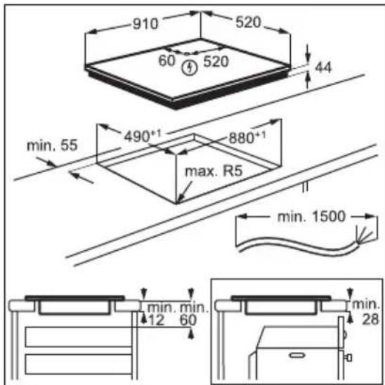
3.2 Built-in hobs
Only use the built-in hobs after you assemble the hob into correct built-in units and work surfaces that align to the standards.
3.3 Connection cable
- The hob is supplied with a connection cable.
• To replace the damaged mains cable, use the cable type: H05V2V2-F which withstands a temperature of 90 °C or higher. Contact an Authorised Service Centre. The connection cable may only be replaced by a qualified electrician.
3.4 Assembly
If you install the hob under a hood, please see the installation instructions of the hood for the minimum distance between the appliances.
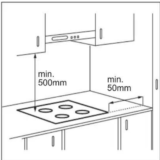
If the appliance is installed above a drawer, the hob ventilation can warm up the items stored in the drawer during the cooking process.
Find the video tutorial "How to install your AEG Induction Hob - Worktop installation" by typing out the full name indicated in the graphic below.

YouTube
www.youtube.com/electrolux www.youtube.com/aeg
| How to install your AEG Induction Hob - Worktop installation |
4. PRODUCT DESCRIPTION
4.1 Cooking surface layout

flowchart
graph TD
    A["1"] --> B["Process Step 1"]
    B --> C["Process Step 2"]
    C --> D["Decision/Branch Path"]
    D --> E["1"]
    D --> F["2"]
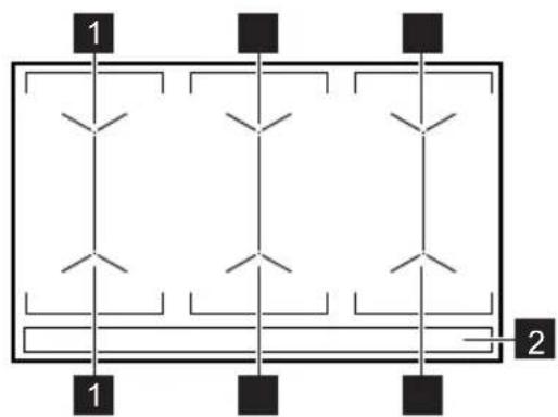
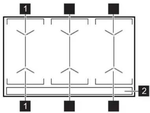
1 Induction cooking surface
2 Control panel
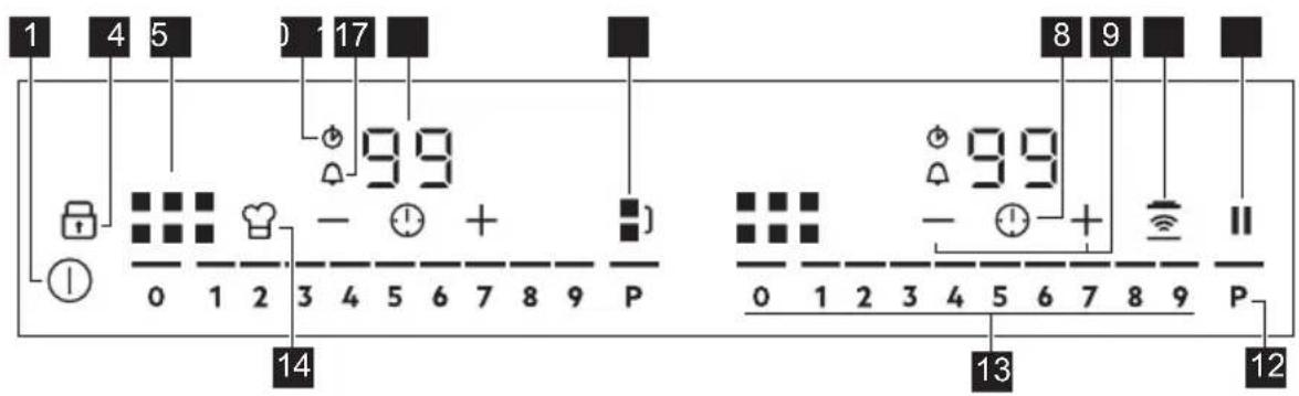
4.2 Control panel layout
text_image
1 4 5 0 17 ■ 99 8 9 0 1 2 3 4 5 6 7 8 9 P 14 99 - + ■ 0 1 2 3 4 5 6 7 8 9 P 13 12Use the sensor fields to operate the appliance. The displays, indicators and sounds tell which functions operate.
Sensor field Comment
| 1 | ➊ | To activate and deactivate the hob. |
| 2 | To activate and deactivate Lock or Child Safety Device. | |
| 3 | To show the active zone. | |
| 4 | CountUp Timer indicator. | |
| 5 | Count Down Timer indicator. | |
| 6 | - Timer display: 00 - 99 minutes. | |
| 7 | To activate and deactivate Bridge and to switch between the modes. | |
| 8 | To select Timer functions. | |
| 9 | +/- | To increase and decrease the time. |
Sensor field Comment
| 10 | To activate and deactivate Hob^2Hood . | |
| 11 | || | To activate and deactivate Pause. |
| 12 | P | To activate PowerBoost. |
| 13 | - To set a heat setting: 0 - 9. | |
| 14 | To activate and deactivate PowerSlide. | |
5. DAILY USE

WARNING!
Refer to Safety chapters.
5.1 Activating and deactivating
Touch for 1 second to activate or deactivate the hob.
The control panel comes on after you activate the hob and goes off after you deactivate the hob.
5.2 Automatic Switch Off
The function deactivates the hob automatically if:
- you do not place any cookware on the hob for 50 seconds,
- you do not set the heat setting for 50 seconds after you place the cookware,
- you spill something or put something on the control panel for more than 10 seconds (a pan, a cloth). When you hear the acoustic signal, the hob deactivates. Remove the object or clean the control panel.
- the hob gets too hot (e.g. when a saucepan boils dry). Let the cooking zone cool down before you use the hob again.
- you do not deactivate a cooking zone or change the heat setting. After some time, the hob deactivates.
The relation between the heat setting and the time after which the hob deactivates:
Heat setting The hob deactivates after
| 1 - 2 6 hours |
| 3 - 4 5 hours |
| 5 4 hours |
| 6 - 9 1.5 hours |
5.3 Using the cooking zone

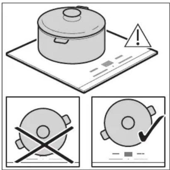
CAUTION!
Do not place hot cookware on the control panel. There is a risk of damage to the electronic parts.
text_image
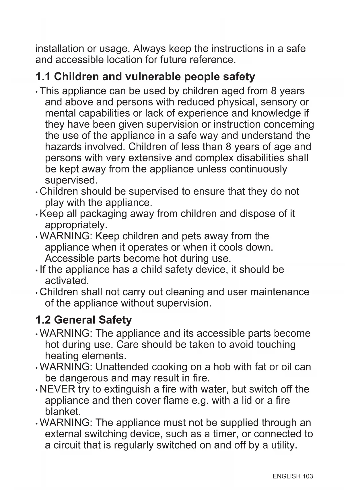
Safety warning illustration showing cooking process with warning symbol and crosshair instructionsPlace the cookware in the centre of the selected zone.
Induction cooking zones adapt to the dimension of the bottom of the cookware automatically.
When you place the cookware in the correct position, the hob recognizes it and the appropriate control bar comes on. A red cooking zone indicator appears above the control bar and indicates the position of the pot.
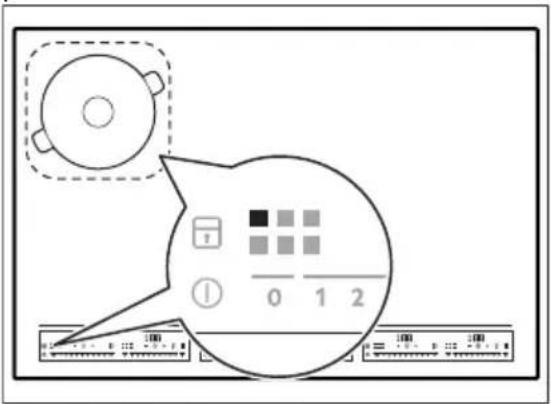
text_image
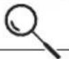
Diagram showing a device interface with labeled buttons and a speech bubble containing binary code, likely for digital display or control.Each square on the control panel represents one cooking zone on the induction cooking surface. Zone indicators show which cooking zone is controlled by the appropriate control bar.
5.4 Heat setting
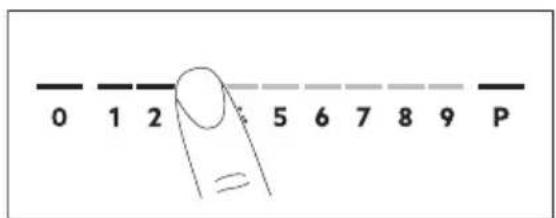
text_image
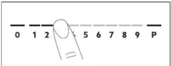
0 1 2 5 6 7 8 9 P-
Press the desired heat setting on the control bar. You can also move your finger along the control bar to set or change the heat setting for a cooking zone.
-
To deactivate a cooking zone, press 0. Once you place a pot on the cooking zone and set the heat setting, it remains the same for 2 minutes after you remove the pot. The control bar and the cooking zone indicator blink for 2 minutes. If you place the pot on the cooking zone again within this time, the heat setting reactivates. Otherwise the cooking zone deactivates.
5.5 PowerBoost
This function activates more power for the appropriate induction cooking zone, depending on the cookware size. The function can be activated only for a limited period of time.
Touch P to activate the function for the cooking zone.
The symbol turns red.
The function deactivates automatically.

For maximum duration values, refer to "Technical data".
5.6 OptiHeat Control (3 step Residual heat indicator)

WARNING!
=/F As long as the indicator is on, there is a risk of burns from residual heat.
The induction cooking zones produce the heat necessary for the cooking process directly in the bottom of the cookware. The glass ceramic is heated by the heat of the cookware.
The indicators / appear when a cooking zone is hot. They show the level of the residual heat for the cooking zones you are currently using.
The indicator may also appear:
• for the neighbouring cooking zones even if you are not using them,
- when hot cookware is placed on cold cooking zone,
- when the hob is deactivated but the cooking zone is still hot.
The indicator disappears when the cooking zone has cooled down.
5.7 Timer

Count Down Timer
Use this function to specify how long a cooking zone should operate during a single cooking session.
First set the heat setting, then set the function.
- Touch to activate the function or change the time.
The timer digits and the indicators and come on the display. turns red, and ☑ turns white.
If the timer is not set, all indicators disappear after 4 seconds.
- Touch or to set the time (00 - 99 minutes).
After 3 seconds, the timer starts to count down automatically. The indicators ⏻, + and — disappear. 🔒 stays red.
When the time comes to an end, a signal sounds and flashes. To stop the signal, touch ⏻.
To deactivate the function: touch ⚠The indicators and come on. Use or —
to set on the display. Alternatively, set the heat level to 0. As a result, a signal sounds and the timer is cancelled.
CountUp Timer
You can use this function to monitor how long a cooking zone operates.
Touch twice to activate the function.
The indicator turns red, the timer starts to count up automatically.
To deactivate the function: touch ⏻. When the indicators light up, touch —
Minute Minder
You can use this function when the hob is activated but no cooking zone operates.
To see the control panel, place a pot on a cooking zone.
-
Touch, until the indicator turns red, to activate the function.
-
Touch or to set the time.
The function starts automatically after 4 seconds. The indicators ⏻, and disappear. 🔒stays red.
When you set the function, you can remove the pot.
When the time comes to an end, a signal sounds and flashes. Touch to stop the signal.
To deactivate the function: touch ⚠. The indicators and light up. Use or — + to set on the display.
The function has no effect on the operation of any cooking zone.
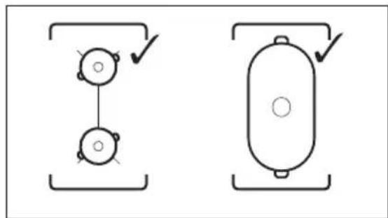
5.8 Bridge
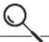
This function connects two cooking zones and they operate as one. You can use the function with large cookware.
- Place the cookware on two cooking zones. The cookware must cover the centres of both zones.
■) turns white.
-
Touch to activate the function.
-
Set the heat setting.
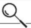
The cookware must cover the centres of both zones but not go beyond the area marking.
natural_image
Two schematic diagrams showing mechanical or electrical components with no text or symbols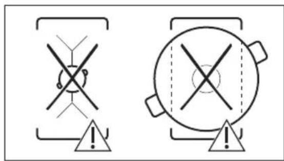
text_image
Warning symbols for safety or hazard detection, showing crossed warning signs and triangular warning elementsTo deactivate the function, touch ■The cooking zones operate independently.
5.9 PowerSlide
This function allows you to adjust the temperature by moving the cookware to a different position on the induction cooking area.
The function divides the induction cooking area into three areas with different heat settings. The hob detects the position of the cookware and adjust the heat setting corresponding with the position.

Use only one pot when you operate the function.
If you want to change the heat setting, lift up the cookware and place it on a different zone.
Sliding the cookware can cause scratches and discolouration of the surface.
- The zone indicator shows both zones in a bridge even if only one of the zones is used.
- You may adjust the heat setting manually only if at least one of the zones is activated automatically.
- You can change the heat settings for each position separately. When you deactivate the hob, it remembers your heat settings and applies it next time you activate the function.
- If you want to change the heat setting, lift up the cookware and place it on a different zone. Sliding the cookware can cause scratches and discolouration of the surface.
Touch 🎨 to activate the function.
The symbol turns red and the control bar displays the default heat setting. All cooking zones operate for 9 minutes.
After 9 minutes, an acoustic signal sounds and the empty cooking zones are
deactivated. Touch 🤒 to resume this function. You can move the pot or place it in a new position.
To modify the default heat setting manually touch the control bar and choose the appropriate level.
- You may change the default heat setting only if the function is active.
- You can change the default heat settings for each position separately. When you deactivate the hob, it remembers your settings and applies them the next time you activate the function.
To deactivate the function, touch 🙏The symbol turns white.
5.10 Pause
When the function is active, and symbols can be used.
The function does not stop the timer functions.
Press || to activate the function.
The symbol turns red. The heat setting is lowered to 1.
To deactivate the function: press ||The symbol turns white. The previous heat setting comes on.
5.11 Lock
You can lock the control panel while the hob operates. It prevents an accidental change of the heat setting.
Set the heat setting first.
Touch 🔒 to activate the function.
The symbol turns red and blinks.
To deactivate the function, touch 🔍 The symbol turns white.

When you deactivate the hob, you also deactivate this function.
5.12 Child Safety Device
This function prevents an accidental operation of the hob.
Activate the hob first and do not set the heat setting.
Touch 🔒 until it turns red to activate the function.
The control bars disappear. Deactivate the hob.

When you deactivate the hob, the function is still active.
To deactivate the function for only one cooking time: Activate the hob with ⏻ ≡ comes on. Touch ⏱ until it turns white. The control bars appear. Set the heat setting within 50 seconds. You can operate the hob. When you deactivate the hob with ⏱ the function is still active.
To deactivate the function permanently: Activate the hob and do not set the heat setting. Touch 📋 until it turns white. The control bars appear. Deactivate the hob.
5.13 OffSound Control (Deactivating and activating the sounds)
Deactivate the hob first.
- Touch for 3 seconds to activate the function. The display comes on and goes out.
- Touch for 3 seconds. b0 or bcomes on.
- Touch of the timer to choose one of the following:
- the sounds are off
- the sounds are on
-
Wait until the hob deactivates automatically to confirm your selection. When the function is set to byou can hear the sounds only when:
-
you touch ①
• Minute Minder comes down - Count Down Timer comes down
- you put something on the control panel.
5.14 Hob²Hood
It is an advanced automatic function which connects the hob to a special hood. Both the hob and the hood have an infrared signal communicator. Speed of the fan is defined automatically on the basis of the mode setting and temperature of the hottest cookware on the hob. You can also operate the fan from the hob manually.
For most of the hoods, the remote system is originally deactivated. Activate it before you use the function. For more information refer to the hood user manual.
Operating the function automatically
To operate the function automatically set the automatic mode to H1 - H6. The hob is originally set to H5. The hood reacts whenever you operate the hob. The hob recognizes the temperature of the cookware automatically and adjusts the speed of the fan.
Activating the light
You can set the hob to activate the light automatically whenever you activate the hob. To do so set the automatic mode to H1 - H6.
The light on the hood deactivates 2 minutes after deactivating the hob.
Automatic modes
| Auto- | Boiling1) | |
| matic light | Frying2) | |
| Mode H0 Off Off Off | ||
| Mode H1 On Off Off | ||
| Mode H23) | On Fan speed 1 | Fan speed 1 |
| Mode H3 On Off Fan speed | 1 | |
| Mode H4 On Fan speed | 1 | Fan speed 1 |
| Mode H5 On Fan speed | 1 | Fan speed 2 |
| Mode H6 On Fan speed | 2 | Fan speed 3 |
1) The hob detects the boiling process and activates the fan speed in accordance with the automatic mode.
2) The hob detects the frying process and activates the fan speed in accordance with the automatic mode.
3) This mode activates the fan and the light and does not rely on the temperature.
Changing the automatic mode
- Deactivate the appliance.
- Touch for 3 seconds.
The display comes on and goes off. - Touch for 3 seconds.
- Touch a few times until comes on.
- Touch of the Timer to select an automatic mode.
When you finish cooking and deactivate the hob, the hood fan may still operate for a certain period of time. After that time the system deactivates the fan automatically and prevents you from an accidental activation of the fan for the next 30 seconds.

To operate the hood directly on the hood panel deactivate the automatic mode of the function.
Operating the fan speed manually
You can also operate the fan from the hob manually.
Touch when the hob is active.
This deactivates automatic operation of the function and allows you to change the fan speed manually.
When you press 📋 you raise the fan speed by one. When you reach an intensive level and press 📋 again, you set the fan speed to 0 which deactivates the hood fan. To start the fan again with the fan speed 1 touch 📋

To activate an automatic operation of the function, deactivate the hob and activate it again.
6. HINTS AND TIPS

WARNING!
Refer to Safety chapters.
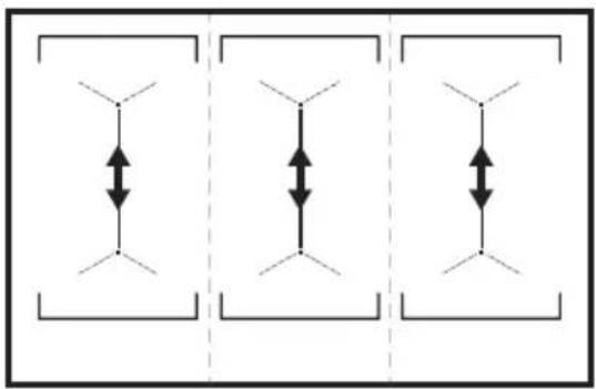
5.15 Power management
If multiple zones are active and the consumed power exceeds the limitation of the power supply, this function divides the available power between all cooking zones. The hob controls heat settings to protect the fuses of the house installation.
- Cooking zones are grouped according to the location and number of the phases in the hob. Each phase has a maximum electricity loading of 3680 W. If the hob reaches the limit of maximum available power within one phase, the power of the cooking zones will be automatically reduced.
- For cooking zones that have a reduced power, the control panel shows the maximum possible heat settings.
- If a higher heat setting is not available reduce it for the other cooking zones first.
• The activation of the function depends on the number and size of pots.
Refer to the illustration for possible combinations in which power can be distributed among the cooking zones.
natural_image
Pure diagram of three identical vertical arrows within rectangular frames, no text or symbols present6.1 Cookware

For induction cooking zones a strong electro-magnetic field creates the heat in the cookware very quickly.
Use the induction cooking zones with suitable cookware.
- The bottom of the cookware must be as thick and flat as possible.
- Ensure pan bases are clean and dry before placing on the hob surface.
- In order to avoid scratches, do not slide or rub the pot across the ceramic glass.
Cookware material
- correct: cast iron, steel, enamelled steel, stainless steel, multi-layer bottom (with a correct marking from a manufacturer).
- not correct: aluminium, copper, brass, glass, ceramic, porcelain.
Cookware is suitable for an induction hob if:
• water boils very quickly on a zone set to the highest heat setting.
- a magnet pulls on to the bottom of the cookware.
Cookware dimensions
- Induction cooking zones adapt to the dimension of the bottom of the cookware automatically.
- The cooking zone efficiency is related to the diameter of the cookware. The cookware with a diameter smaller than the minimum receives only a part of the power generated by the cooking zone.
- For both safety reasons and optimal cooking results, do not use cookware larger than indicated in "Cooking zones specification". Avoid keeping cookware close to the control panel during the cooking session. This might impact the functioning of the control panel or accidentally activate hob functions.

Refer to "Technical data".
6.2 The noises during operation
If you can hear:
- crack noise: cookware is made of different materials (a sandwich construction).
- whistle sound: you use a cooking zone with a high power level and the cookware is made of different materials (a sandwich construction).
- humming: you use a high power level.
- clicking: electric switching occurs.
- hissing, buzzing: the fan operates.
The noises are normal and do not indicate any malfunction.
6.3 Öko Timer (Eco Timer)
To save energy, the heater of the cooking zone deactivates before the count down timer sounds. The difference in the operation time depends on the heat setting level and the length of the cooking operation.
6.4 Examples of cooking applications
The correlation between the heat setting of a zone and its consumption of power is not linear. When you increase the heat setting, it is not proportional to the increase of the consumption of power. It means that a cooking zone with the medium heat setting uses less than a half of its power.

The data in the table is for guidance only.
| Heat setting Use to: Time | Hints (min) | |
| 1 Keep cooked food warm. as neces- | sary | Put a lid on the cookware. |
| 1 - 2 Hollandaise sauce, melt: butter, choco-late, gelatine. | 5 - 25 Mix from time to time. | |
| 1 - 2 Solidify: fluffy omelettes, baked eggs. 10 - 40 Cook with a lid on. | ||
| Heat setting Use to: Time | Hints(min) |
| 2 - 3 Simmer rice and milkbased dishes,heat up ready-cooked meals. | 25 - 50 Add at least twice as much liquid as rice, mix milk dishes halfway through the procedure. |
| 3 - 4 Steam vegetables, fish, meat. 20 - 45 Add a couple of tablespoons of liquid. | |
| 4 - 5 Steam potatoes. 20 - 60 Use max. 14 I of water for 750 g of po-tatoes. | |
| 4 - 5 Cook larger quantities of food, stewsand soups. | 60 - 150 Up to 3 l of liquid plus ingredients. |
| 6 - 7 Gentle fry: escalope, veal cordon bleu,cutlets, rissoles, sausages, liver, roux,eggs, pancakes, doughnuts. | as neces-sary Turn halfway through. |
| 7 - 8 Heavy fry, hash browns, loin steaks,steaks. | 5 - 15 Turn halfway through. |
| 9 Boil water, cook pasta, sear meat (goulash, pot roast), deep-fry chips. | |
| P | Boil large quantities of water. PowerBoost is activated. |
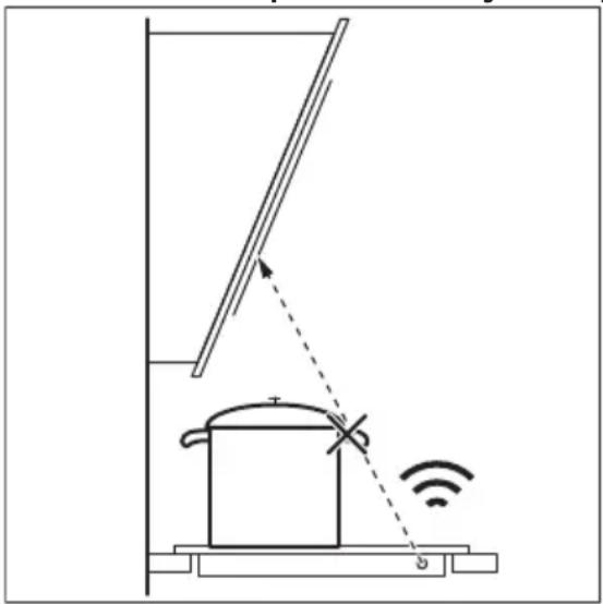
6.5 Hints and Tips for Hob ^2 Hood
When you operate the hob with the function:
- Protect the hood panel from direct sunlight.
- Do not spot halogen light on the hood panel.
- Do not cover the hob control panel.
- Do not interrupt the signal between the hob and the hood (e.g. with the hand, a cookware handle or a tall pot). See the picture.
The hood in the picture is only exemplary.
natural_image
Diagram of a smart heating or monitoring system with a pot, antenna, and wireless signal icon (no text labels)
Other remotely controlled appliances may block the signal. Do not use any such appliances near to the hob while Hob ^2 Hood is on.
Cooker hoods with the Hob ^2 Hood function To find the full range of cooker hoods which work with this function refer to our consumer website. The AEG cooker hoods that work with this function must have the symbol 📞
7. CARE AND CLEANING

WARNING!
Refer to Safety chapters.
7.1 General information
- Clean the hob after each use.
• Always use cookware with a clean base. - Scratches or dark stains on the surface have no effect on how the hob operates.
- Use a special cleaner suitable for the surface of the hob.
- Use a special scraper for the glass.
7.2 Cleaning the hob
- Remove immediately: melted plastic, plastic foil, sugar and food with sugar,
otherwise, the dirt can cause damage to the hob. Take care to avoid burns. Use a special hob scraper on the glass surface at an acute angle and move the blade on the surface.
- Remove when the hob is sufficiently cool: limescale rings, water rings, fat stains, shiny metallic discoloration. Clean the hob with a moist cloth and a non-abrasive detergent. After cleaning, wipe the hob dry with a soft cloth.
- Remove shiny metallic discoloration: use a solution of water with vinegar and clean the glass surface with a cloth.
8. TROUBLESHOOTING

WARNING!
Refer to Safety chapters.
8.1 What to do if...
Problem Possible cause Remedy
| You cannot activate or operate the hob. | The hob is not connected to an electrical supply or it is connected incorrectly. | Check if the hob is correctly connected to the electrical supply. |
| The fuse is blown. Make sure that the fuse is the cause of | the malfunction. If the fuse is blown again and again, contact a qualified electrician. | |
| You touched 2 or more sensor fields at the same time. | Touch only one sensor field. | |
| Pause operates. Refer to "Daily use". | ||
| There is water or fat stains on the control panel. | Clean the control panel. | |
| You cannot select the maximum heat setting for one of the cooking zones. | The other zones consume the maximum available power. Your hob works properly. | Reduce the heat setting of the other cooking zones connected to the same phase. Refer to "Power management". |
| An acoustic signal sounds and the hob deactivates. An acoustic signal sounds when the hob is deactivated. | You put something on one or more sensor fields. | Remove the object from the sensor fields. |
Problem Possible cause Remedy
| The hob deactivates. You put something on the sensor field 1 | Remove the object from the sensor field. | |
| Residual heat indicator does not come on. | The zone is not hot because it operated only for a short time or the sensor is damaged. | If the zone operated sufficiently long to be hot, speak to an Authorised Service Centre. |
| Hob2Hood does not work. You covered the control panel. Remove the object from the control panel. | ||
| You use a very tall pot which blocks the signal. | Use a smaller pot, change the cooking zone or operate the hood manually. | |
| There is no sound when you touch the panel sensor fields. | The sounds are deactivated. Activate the sounds. Refer to "Daily use". | |
| comes on. | Child Safety Device or Lock operates. | Refer to "Daily use". |
| The control bar blinks. There is no cookware on the zone or the zone is not fully covered. | Put cookware on the zone so that it fully covers the cooking zone. | |
| The cookware is unsuitable. Use suitable cookware. Refer to "Hints and tips". | ||
| The diameter of the bottom of the cookware is too small for the zone. | Use cookware with correct dimensions. Refer to "Technical data". | |
| PowerSlide operates. Two pots are placed on the flexible induction cooking area. | Use only one pot. Refer to "Flexible induction cooking area". | |
| and a number come on. | There is an error in the hob. Deactivate the hob and activate it again after 30 seconds. If comes on again, disconnect the hob from the electrical supply. After 30 seconds, connect the hob again. If the problem continues, speak to an Authorised Service Centre. | |
| You can hear a constant beep noise. | The electrical connection is incorrect. | Disconnect the hob from the electrical supply. Ask a qualified electrician to check the installation. |
8.2 If you cannot find a solution...
If you cannot find a solution to the problem yourself, contact your dealer or an Authorised Service Centre. Give the data from the rating plate. Make sure, you operated the hob correctly. If not the
servicing by a service technician or dealer will not be free of charge, also during the warranty period. The information about guarantee period and Authorised Service Centres are in the guarantee booklet.
9. TECHNICAL DATA
9.1 Rating plate
Model IKE96654FB PNC 949 597 619 00
Typ 61 E6A 04 AA 400 V 3N 50 - 60 Hz
Induction 11.0 kW Made in: Germany
Ser.Nr. 11.0 kW
AEG
9.2 Cooking zones specification
| Cooking zone Nominal power (maximum heat setting) [W] | PowerBoost [W] | PowerBoost maximum duration [min] | Cookware diameter [mm] |
| Left front 2300 3200 10 125 - 210 | |||
| Left rear 2300 3200 10 125 - 210 | |||
| Middle front 2300 3200 10 125 - 210 | |||
| Middle rear 2300 3200 10 125 - 210 | |||
| Right front 2300 3200 10 125 - 210 | |||
| Right rear 2300 3200 10 125 - 210 |
The power of the cooking zones can be different in some small range from the data in the table. It changes with the material and dimensions of the cookware.
For optimal cooking results use cookware no larger than the diameter in the table.
10. ENERGY EFFICIENCY
10.1 Product Information\*
Model identification IKE96654FB
| Type of hob Built-In Hob | ||
| Number of cooking areas | 3 | |
| Heating technology Induction | ||
| Length (L) and width (W) of the cooking area | Left | L 37.9 cmW 22.0 cm |
| Length (L) and width (W) of the cooking area | Middle | L 37.9 cmW 22.0 cm |
| Length (L) and width (W) of the cooking area | Right L 37.9 cm | W 22.0 cm |
| Energy consumption of the cooking area (EC electric cooking) | Left 186.8 Wh / kg |
| Energy consumption of the cooking area (EC electric cooking) | Middle 186.8 Wh / kg |
| Energy consumption of the cooking area (EC electric cooking) | Right 186.8 Wh / kg |
| Energy consumption of the hob (EC electric hob) 186.8 Wh / kg |
* For European Union according to EU 66/2014. For Belarus according to STB 2477-2017, Annex A. For Ukraine according to 742/2019.
EN 60350-2 - Household electric cooking appliances - Part 2: Hobs - Methods for measuring performance.
The energy measurements referring to the cooking area are identified by the markings of the respective cooking zones.
10.2 Energy saving
You can save energy during everyday cooking if you follow below hints.
- When you heat up water, use only the amount you need.
- If it is possible, always put the lids on the cookware.
- Before you activate the cooking zone put the cookware on it.
- Put the smaller cookware on the smaller cooking zones.
- Put the cookware directly in the centre of the cooking zone.
- Use the residual heat to keep the food warm or to melt it.
11. ENVIRONMENTAL CONCERNS
Recycle materials with the symbol Put the packaging in relevant containers to recycle it. Help protect the environment and human health by recycling waste of electrical and electronic appliances. Do not dispose of
appliances marked with the symbol with the household waste. Return the product to your local recycling facility or contact your municipal office.
PARIMATE TULEMUSTE SAAVUTAMISEKS
text_image
How to install your AEG Induction Hob - Worktop installation4. TOOTE KIRJELDUS
text_image
Safety warning illustration showing a cooking pot with warning symbols and three safety symbols below.text_image
Diagram showing a speech bubble with numbered buttons and a timer, likely representing a digital interface or control panel.natural_image
Two schematic diagrams showing a vertical structure with circular elements connected by lines, each enclosed in a rectangular frame (no text or symbols)
text_image
Warning symbols for safety or hazard detection, showing crossed warning signs and triangular warning symbols with exclamation marks.natural_image
Pure diagram of three identical vertical arrows within rectangular frames, no text or symbols presentnatural_image
Diagram of a cooking pot setup with a lever and sensor, showing no text or symbols1. ⚠TURVALLISUUSTIEDOT
How to install your AEG Induction Hob - Worktop installation

4. TUOTEKUVAUS
4.1 Keittoalueet
flowchart
graph TD
    A["1"] --> B["1"]
    C["1"] --> D["1"]
    E["1"] --> F["1"]
    G["1"] --> H["1"]
    I["1"] --> J["1"]
    K["1"] --> L["1"]
    M["1"] --> N["1"]
    O["1"] --> P["1"]
    Q["1"] --> R["1"]
    S["1"] --> T["1"]
    U["1"] --> V["1"]
    W["1"] --> X["1"]
    Y["1"] --> Z["1"]
    AA["1"] --> AB["1"]
    AC["1"] --> AD["1"]
    AE["1"] --> AF["1"]
    AG["1"] --> AH["1"]
    AI["1"] --> AJ["1"]
    AK["1"] --> AL["1"]
    AM["1"] --> AN["1"]
    AO["1"] --> AP["1"]
    AQ["1"] --> AR["1"]
    AS["1"] --> AT["1"]
    AU["1"] --> AV["1"]
    AW["1"] --> AX["1"]
    AY["1"] --> AZ["1"]
    BA["1"] --> BB["1"]
    BC["1"] --> BD["1"]
    BE["1"] --> BF["1"]
    BG["1"] --> BH["1"]
    BI["1"] --> BJ["1"]
    BK["1"] --> BL["1"]
    BM["1"] --> BN["1"]
    BO["1"] --> BP["1"]
    BQ["1"] --> BR["1"]
    BS["1"] --> BT["1"]
    BU["1"] --> BV["1"]
    BW["1"] --> BX["1"]
    BY["1"] --> BZ["1"]
    CA["1"] --> CB["1"]
    CC["1"] --> CD["1"]
    CE["1"] --> CF["1"]
    DG["1"] --> DH["1"]
    DI["1"] --> DJ["1"]
    DK["1"] --> DL["1"]
text_image
Safety warning illustration showing a cooking pot with warning symbols and three safety instructions for cross-sections.text_image
Diagram showing a speech bubble with numbered buttons and a timer, likely representing a timer or dial indicator system.natural_image
Two schematic diagrams showing a pulley system with two circular components and directional arrows, no text or symbols present.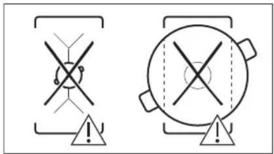
text_image
Two safety warning symbols: crossed-out cross symbol and circular warning symbol with exclamation marknatural_image
Pure diagram of three identical rectangular boxes with vertical double-headed arrows, no text or symbols present.natural_image
Diagram of a smart heating or monitoring system with a pot, antenna, and wireless signal icon (no text labels)
How to install your AEG Induction Hob - Worktop installation

4. DESCRIPTION DE L'APPAREIL
text_image
Safety warning illustration showing a cooking pot with warning symbol and three safety symbols: crossed-out circle, no cross, and checkmark.text_image
Diagram showing a device with a speech bubble containing a color-coded grid, alongside a ruler and a speaker icon.natural_image
Two schematic diagrams showing mechanical or electrical components with no text or symbols
text_image
Two warning symbols with crosshairs and triangular warning indicators, one containing a crossed-out circle and the other a filled circle.natural_image
Pure diagram of three identical vertical arrows within rectangular frames, no text or symbols present6. CONSEILS

AVERTISSEMENT!
natural_image
Diagram of a smart air lift with a tank and signal icon, no text or symbols present
Type 61 E6A 04 AA 400 V 3N, 50 - 60 Hz
How to install your AEG Induction Hob - Worktop installation
4. TERMÉKLEÍRÁS
text_image
Safety warning illustration showing a cooking pot with warning symbol and three safety symbols: crossed-out circle, no cross, and checkmark.text_image
Diagram showing a speech bubble with numbered buttons and a ruler, likely illustrating a timer or timer function.natural_image
Two schematic diagrams showing mechanical or electrical components with no text or symbols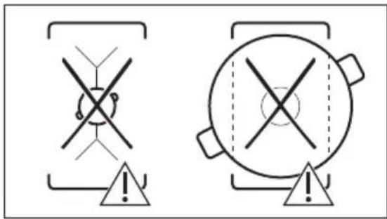
text_image
Warning symbols for safety or hazard detection, showing crossed warning signs and triangular warning symbols with exclamation marks.natural_image
Pure diagram of three identical vertical arrows within rectangular frames, no text or symbols present6. HASZNOS TANÁCSOK ÉS JAVASLATOK

FIGYELMEZTETÉS!
natural_image
Diagram of a smart air lift system with a tank and sensor, showing signal flow (no text or symbols)
FYRIR FULLKOMINN ÁRANGUR
text_image
How to install your AEG Induction Hob - Worktop installation4. VÖRULÝSING
4.1 Uppsetning eldunarhellu

flowchart
graph TD
    A["1"] --> B["1"]
    C["1"] --> D["1"]
    E["1"] --> F["1"]
    G["1"] --> H["1"]
    I["1"] --> J["1"]
    K["1"] --> L["1"]
    M["1"] --> N["1"]
    O["1"] --> P["1"]
    Q["1"] --> R["1"]
    S["1"] --> T["1"]
    U["1"] --> V["1"]
    W["1"] --> X["1"]
    Y["1"] --> Z["1"]
    AA["1"] --> AB["1"]
    AC["1"] --> AD["1"]
    AE["1"] --> AF["1"]
    AG["1"] --> AH["1"]
    AI["1"] --> AJ["1"]
    AK["1"] --> AL["1"]
    AM["1"] --> AN["1"]
    AO["1"] --> AP["1"]
    AQ["1"] --> AR["1"]
    AS["1"] --> AT["1"]
    AU["1"] --> AV["1"]
    AW["1"] --> AX["1"]
    AY["1"] --> AZ["1"]
    BA["1"] --> BB["1"]
    BC["1"] --> BD["1"]
    BE["1"] --> BF["1"]
    BG["1"] --> BH["1"]
    BI["1"] --> BJ["1"]
    BK["1"] --> BL["1"]
    BM["1"] --> BN["1"]
    BO["1"] --> BP["1"]
    BQ["1"] --> BR["1"]
    BS["1"] --> BT["1"]
    BU["1"] --> BV["1"]
    BW["1"] --> BX["1"]
    BY["1"] --> BZ["1"]
    CA["1"] --> CB["1"]
    CC["1"] --> CD["1"]
    CE["1"] --> CF["1"]
    DG["1"] --> DH["1"]
    DI["1"] --> DJ["1"]
    DK["1"] --> DL["1"]
text_image
Safety warning illustration showing cooking process with warning triangle and cross symboltext_image
Diagram showing a device with a speech bubble containing icons and numerical labels, likely illustrating a measurement or control interface.natural_image
Two schematic diagrams showing a pulley system with two wheels and a central cylinder, each enclosed in a rectangular frame (no text or symbols)
text_image
Warning symbols for safety or hazard detection, showing crossed warning signs and triangular warning symbols with exclamation marks.natural_image
Pure diagram of three identical rectangular blocks with vertical double-headed arrows, no text or symbols present.6. GÓD RÁD

AĐVÖRUN!
natural_image
Diagram of a cooking setup with a pot, ladder, and Wi-Fi signal (no text or symbols)
text_image
How to install your AEG Induction Hob - Worktop installation4. IZSTRĀDĀJUMA APRAKSTS
text_image
Safety warning illustration showing a cooking pot with warning symbols and three safety instructions for crosshair detection.text_image
Diagram showing a speech bubble with numbered indicators and control buttons, likely representing a system or interface design.natural_image
Two schematic diagrams showing a vertical structure with circular elements and directional arrows, no text or symbols present.
text_image
Two safety warning symbols: crossed-out cross symbol and circular warning symbol, both with triangular warning indicators.natural_image
Pure diagram of three identical vertical arrows within rectangular frames, no text or symbols present6. PADOMI UN IETEIKUMI

BRĪDINĀJUMS!
natural_image
Diagram of a smart heating or monitoring system with a pot, antenna, and wireless signal icon (no text labels)
How to install your AEG Induction Hob - Worktop installation
4. GAMINIO APRAŠYMAS
text_image
Safety warning illustration showing cooking process with warning symbol and three safety symbols belowtext_image
Diagram showing a speech bubble with numbered indicators and a circular icon containing a grid, likely representing a UI or control panel.natural_image
Two schematic diagrams showing circular components connected by lines, with checkmarks indicating alignment or adjustment (no text or symbols)
text_image
Two safety warning symbols: crossed-out cross symbol and circular warning symbol with exclamation marknatural_image
Pure diagram of three identical vertical arrows within rectangular frames, no text or symbols present6. PATARIMAI

JSPÈJIMAS!
Žr. saugos skyrius.
6.1 Indai

Indukcinèse kaitvietèse veikiantis stiprus
natural_image
Diagram of a smart heating setup with a pot, antenna, and wireless signal icon (no text or symbols)| How to install your AEG Induction Hob - Worktop installation |  |
4. ОПИС НА ПРОИЗВОДОТ
text_image
Safety warning illustration showing a cooking pot with warning symbols and three safety instructions for cross-sections.text_image
Diagram showing a device interface with a speech bubble containing a color-coded grid and control buttons, alongside a ruler for scale.natural_image
Two schematic diagrams showing mechanical or electrical components with no text or symbols
text_image
Two safety warning symbols: crossed cross and triangle with warning arrows, indicating incorrect or invalid conditions.natural_image
Pure diagram of three identical rectangular boxes with vertical double-headed arrows, no text or symbols present.6. ПОМОШ И СОВЕТИ

ПРЕДУПРЕДУВАЊЕ!
natural_image
Diagram of a smart air lift or control system with a tank, sensor, and signal icon (no text labels)
How to install your AEG Induction Hob - Worktop installation
4. PRODUKTBESKRIVELSE
text_image
Diagram showing a device with a speech bubble containing binary code (0, 1, 2) and control buttons, alongside a ruler for scale.Hvert kvadrat i betjeningspanelet representerer en kokesone på induksjonskokeoverflaten. Soneindikatorer viser hvilken kokesone som kontrolleres av passende betjeningslinje.
5.4 Varmeinnstilling
text_image
0 1 2 5 6 7 8 9 P- Trykk på ønsket effekttrinn på betjeningslinjen. Du kan også bevege fingeren langs betjeningslinjen for å angi eller endre effekttrinnet for en kokesone.
- For å deaktivere en kokesone, trykk på 0. Så snart du setter et kokekar på sonen og stiller inn varmen forblir det likt i 2 minutter etter at du tar bort karet. Betjeningslinjen og kokesoneindikatoren blinker i 2 minutter. Hvis du plasserer kokekaret på konesonen igjen innenfor denne tiden, reaktiveres varmeinnstillingen. Ellers deaktiveres konesonen.
5.5 PowerBoost
natural_image
Two schematic diagrams showing a pulley system with circular components and directional arrows, no text or symbols present.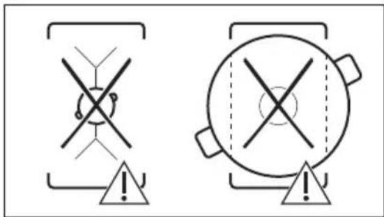
text_image
Two safety warning symbols: crossed-out cross symbol and circular warning symbol with exclamation marknatural_image
Pure diagram of three identical vertical arrows within rectangular frames, no text or symbols present6. RÅD OG TIPS

ADVARSEL!
natural_image
Diagram of a smart air lift system with a tank, sensor, and signal waves (no text or symbols)
text_image
How to install your AEG Induction Hob - Worktop installation4. OPIS URZĄDZENIA
text_image
Safety warning illustration showing a cooking pot with warning symbol and three safety symbols below.text_image
Diagram showing a device interface with labeled buttons and a speech bubble containing binary code (0, 1, 2)natural_image
Two schematic diagrams showing mechanical or electrical components with no text or symbols
text_image
Warning symbols for safety or hazard detection, showing crossed warning signs and triangular warning symbols with exclamation marks.natural_image
Pure diagram of three identical vertical arrows within rectangular frames, no text or symbols present6. WSKAZÓWKI I PORADY

OSTRZEŻENIE!
natural_image
Diagram of a smart heating or monitoring system with a pot, antenna, and wireless signal icon (no text labels)
Typ 61 E6A 04 AA 400 V, 3N, 50–60 Hz
How to install your AEG Induction Hob - Worktop installation

4. ОПИС ПРОИЗВОДА
text_image
Safety warning illustration showing a cooking pot with warning symbols and three safety diagrams below.text_image
Diagram showing a device with labeled buttons and a speech bubble containing a grid, likely illustrating a control or measurement system.natural_image
Two schematic diagrams showing mechanical or electrical components with no text or symbols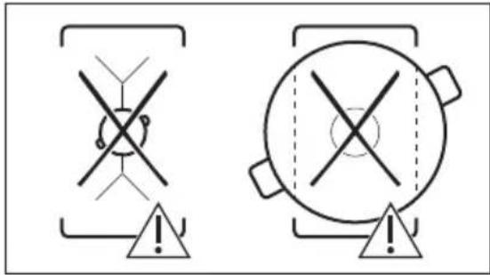
text_image
Two warning symbols with crosshairs and triangular warning elements, one containing a circular symbol and the other a circular target.natural_image
Pure diagram of three vertical arrows within rectangular frames, no text or symbols present6. КОРИСНИ САВЕТИ

УПОЗОРЕЊЕ!
natural_image
Diagram of a cooking pot setup with a lever and sensor, showing no text or symbolsHow to install your AEG Induction Hob - Worktop installation
4. POPIS VÝROBKU
text_image
Safety warning illustration showing a cooking pot with warning symbols and three safety diagrams below.text_image
Diagram showing a device with labeled buttons and a speech bubble containing numeric values 0, 1, 2.natural_image
Two schematic diagrams showing a pulley system with circular components and directional arrows, no text or symbols present.
text_image
Two safety warning symbols: crossed-out cross symbol and circular target with cross symbol, both marked with an exclamation mark.natural_image
Pure diagram of three identical vertical arrows within rectangular frames, no text or symbols present6. TIPY A RADY

VAROVANIE!
natural_image
Diagram of a cooking pot setup with a lever and sensor, showing no text or symbols
Iné spotrebiče ovládané na diaľku môžu blokovat' signál. Nepoužívajte takéto spotrebiče v blízkosti varného panela pri zapnutej funkcií Hob²Hood.
Odsávače pár s funkciou Hob²Hood
How to install your AEG Induction Hob - Worktop installation

4. OPIS IZDELKA
text_image
Safety warning illustration showing a cooking pot with warning symbols and three safety instructions for cross-sections.text_image
Diagram showing a speech bubble with numbered indicators and a ruler, likely illustrating a measurement or calibration system.natural_image
Two schematic diagrams showing mechanical or electrical components with no text or symbols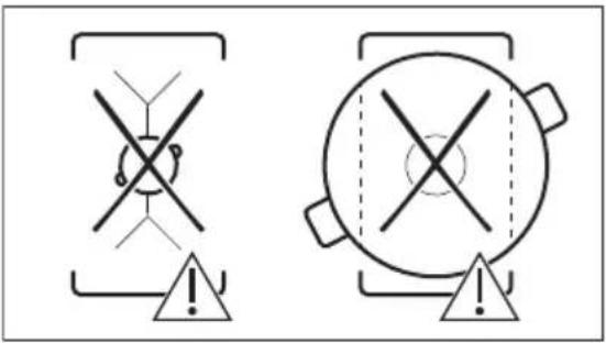
text_image
Two safety warning symbols: crossed-out cross symbol and circular warning circle with cross symbol, both enclosed in triangular warning envelopes.natural_image
Pure diagram of three identical vertical arrows within rectangular frames, no text or symbols present6. NAMIGI IN NASVETI

OPOZORILO!
natural_image
Diagram of a smart air lift or control system with a pot, sensor, and signal icon (no text labels)Vrsta 61 E6A 04 AA 400 V, 3N, 50–60 Hz
How to install your AEG Induction Hob - Worktop installation

4. PRODUKTBESKRIVNING
text_image
Safety warning illustration showing a cooking pot with warning symbols and three safety diagrams below.text_image
Diagram showing a speech bubble with numbered buttons and icons, likely representing a timer or timer interface.natural_image
Two schematic diagrams showing mechanical or electrical components with no text or symbols
text_image
Safety warning symbols for crosshair and circular device, both marked with exclamation marksnatural_image
Pure diagram of three identical vertical arrows within rectangular frames, no text or symbols present6. RÅD OCH TIPS

WARNING!
natural_image
Diagram of a smart air lift or control system with a tank, sensor, and signal icon (no text labels)