USER MANUAL AVD97 AIWA
For assistance and information
call toll free 1-800-BUY-AIWA
(United States and Puerto Rico)
WARNING
TO REDUCE THE RISK OF FIRE OR ELECTRIC SHOCK, DO NOT EXPOSE THIS APPLIANCE TO RAIN OR MOISTURE.

Explanation of Graphical Symbols:

The lightning flash with arrowhead symbol, within an equilateral triangle, is intended to alert the user to the presence of uninsulated "dangerous voltage" within the product's enclosure that may be of sufficient magnitude to constitute a risk of electric shock to persons.

The exclamation point within an equilateral triangle is intended to alert the user to the presence of important operating and maintenance (servicing) instructions in the literature accompanying the appliance.
Owner's record
For your convenience, record the model number and serial number (you will find them on the rear of your unit) in the space provided below. Please refer to them when you contact your Aiwa dealer in case of difficulty.
| Model No. Serial No. (Lot No.) |
| AV-D97 | |
1 ENGLISH
PRECAUTIONS
Read the Operating Instructions carefully and completely before operating the unit. Be sure to keep the Operating Instructions for future reference. All warnings and cautions in the Operating Instructions and on the unit should be strictly followed, as well as the safety suggestions below.
Installation
1 Water and moisture - Do not use this unit near water, such as near a bathtub, washbowl, swimming pool, or the like.
2 Heat - Do not use this unit near heat sources, including heating vents, stoves, or other appliances that generate heat. It also should not be placed in temperatures less than 5^ (41^) or higher than 35^ (95^) .
3 Mounting surface - Place the unit on a flat, even surface.
4 Ventilation - The unit should be situated with adequate space around it so that proper heat ventilation is assured. Allow 10cm (4 in.) clearance from the rear and the top of the unit, and 5cm (2 in.) from each side.
- Do not place the unit on a bed, rug, or similar surface that may block the ventilation openings.
- Do not install the unit in a bookcase, cabinet, or airtight rack where ventilation may be impeded.
5 Objects and liquid entry - Take care that objects or liquids do not get inside the unit through the ventilation openings.
6 Carts and stands When placed or mounted on a stand or cart, the unit should be moved with care. Quick stops, excessive force, and uneven surfaces may cause the unit or cart to overturn or fall.
7 Wall or ceiling mounting—The unit should not be mounted on a wall or ceiling, unless specified in the Operating Instructions.

Electric Power
1 Power sources — Connect this unit only to power sources specified in the Operating Instructions, and as marked on the unit.
2 Polarization - As a safety feature, some units are equipped with polarized AC power plugs which can only be inserted one way into a power outlet. If it is difficult or impossible to insert the AC power plug into an outlet, turn the plug over and try again. If it is not still inserted easily into the outlet, please call a qualified service technician to service or replace the outlet. To avoid defeating the safety feature of the polarized plug, do not force it into a power outlet.
3 AC power cord
- When disconnecting the AC power cord, pull it out by the AC power plug. Do not pull the cord itself.
- Never handle the AC power plug with wet hands, as this could result in fire or shock.
- Power cords should be firmly secured to avoid being severely bent, pinched, or walked upon. Pay particular attention to the cord from the unit to the power socket.
- Avoid overloading AC outlets and extension cords beyond their capacity, as this could result in fire or shock.
4 Extension cord - To help prevent electric shock, do not use a polarized AC power plug with an extension cord, receptacle, or other outlet unless the polarized plug can be completely inserted to prevent exposure of the blades of the plug.
5 When not in use — Unplug the AC power cord from the AC power outlet if the unit will not be used for several months or more. When the cord is plugged in, a small amount of current continues to flow to the unit, even when the power is turned off.
Outdoor Antenna
1 Power lines - When connecting an outdoor antenna, make sure it is located away from power lines.
2 Outdoor antenna grounding - Be sure the antenna system is properly grounded to provide protection against unexpected voltage surges or static electricity build-up. Article 810 of the National Electrical Code, ANSI/NFPA70, provides information on proper grounding of the mast, supporting structure, and the lead-in wire to the antenna discharge unit, as well as the size of the grounding unit, connection to grounding terminals, and requirements for grounding terminals themselves.
Antenna Grounding According to the National Electrical Code
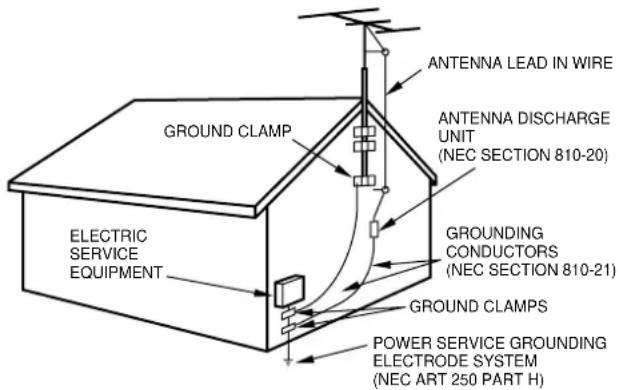
NEC-NATIONAL ELECTRICAL CODE
Maintenance
Clean the unit only as recommended in the Operating Instructions.
Damage Requiring Service
Have the unit serviced by a qualified service technician if:
- The AC power cord or plug has been damaged
- Foreign objects or liquid have gotten inside the unit
- The unit has been exposed to rain or water
- The unit does not seem to operate normally
- The unit exhibits a marked change in performance
- The unit has been dropped, or the cabinet has been damaged
DO NOT ATTEMPT TO SERVICE THE UNIT YOURSELF.
Check your accessories
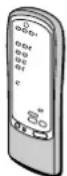
Remote control

FM antenna AM antenna

Operating Instructions, etc.
TABLE OF CONTENTS
PRECAUTIONS 1
PREPARATIONS
CONNECTIONS 3
BEFORE OPERATION 7
SOUND
CUSTOM AUDIOADJUSTMENT 8
ELECTRONIC GRAPHIC EQUALIZER 9
DSP SURROUND 10
BASIC OPERATIONS
SELECTION OF AUDIO/VIDEO SOURCE. 11
RECORDING AN AUDIO SOURCE 12
RADIO RECEPTION
MANUAL TUNING 13
PRESETTING STATIONS 14
DOLBY SURROUND AND DTS SURROUND
TROUBLESHOOTING GUIDE 24
PARTS INDEX 24
APPENDIX
ID CODES FOR TV. A-1
ID CODES FOR CABLE TV A-3
ID CODES FOR VCR A-4
ID CODES FOR CD PLAYER A-5
ID CODES FOR DSS SATELLITE A-6
CONNECTIONS
Before connecting the AC cord
The rated voltage of your unit shown on the rear panel is 230 V AC. Check that the rated voltage matches your local voltage.
IMPORTANT
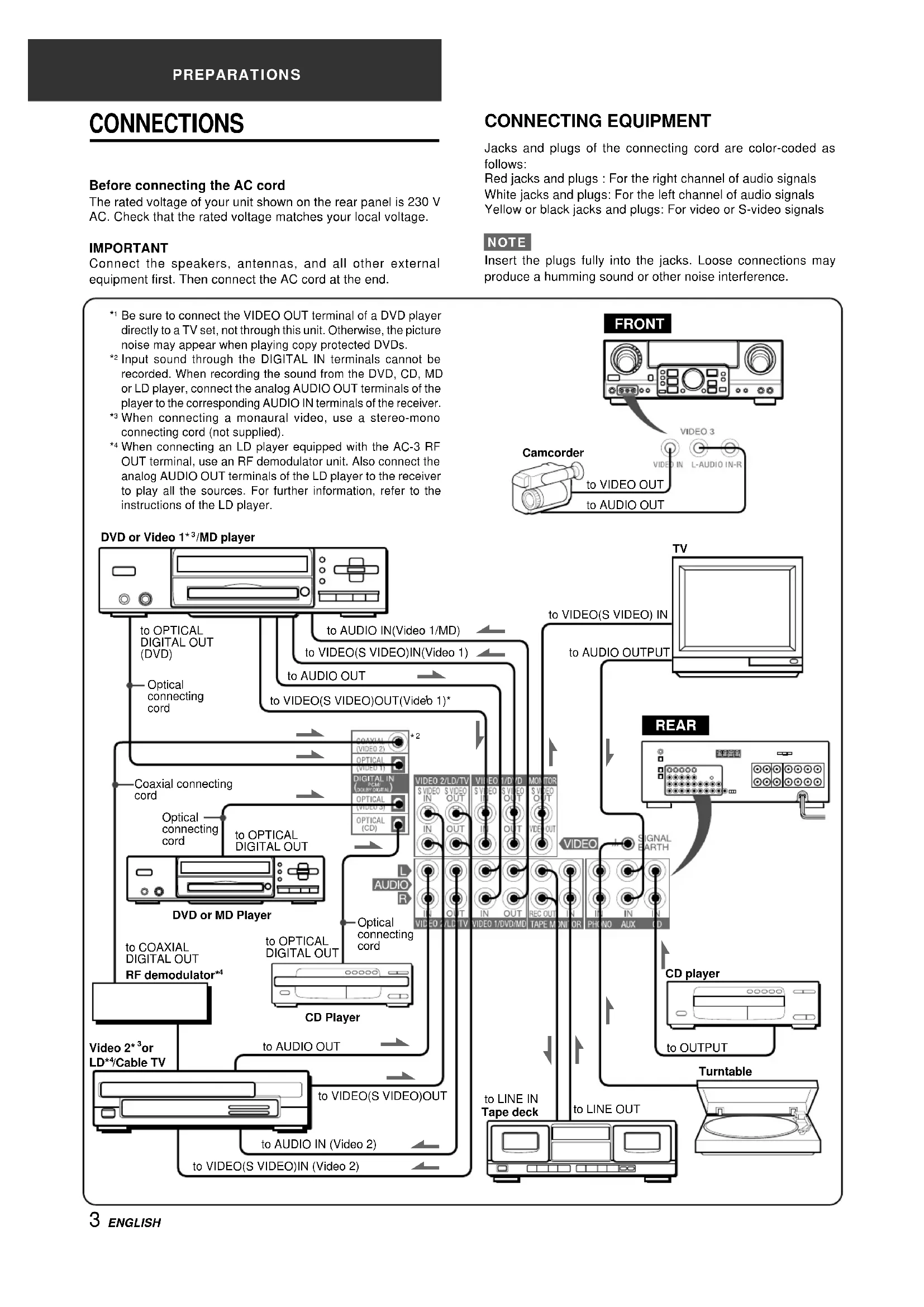
Connect the speakers, antennas, and all other external equipment first. Then connect the AC cord at the end.
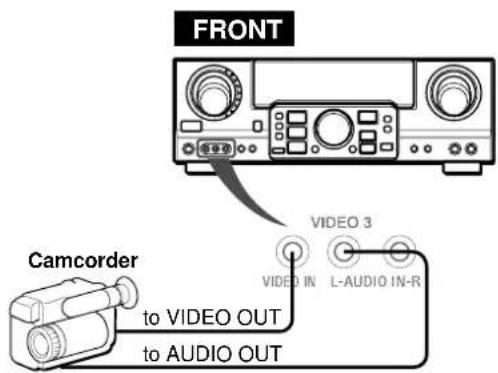
CONNECTING EQUIPMENT
Jacks and plugs of the connecting cord are color-coded as follows:
Red jacks and plugs : For the right channel of audio signals White jacks and plugs: For the left channel of audio signals Yellow or black jacks and plugs: For video or S-video signals
NOTE
Insert the plugs fully into the jacks. Loose connections may produce a humming sound or other noise interference.
1 Be sure to connect the VIDEO OUT terminal of a DVD player directly to a TV set, not through this unit. Otherwise, the picture noise may appear when playing copy protected DVDs.
2 Input sound through the DIGITAL IN terminals cannot be recorded. When recording the sound from the DVD, CD, MD or LD player, connect the analog AUDIO OUT terminals of the player to the corresponding AUDIO IN terminals of the receiver.
3 When connecting a monaural video, use a stereo-mono connecting cord (not supplied).
4 When connecting an LD player equipped with the AC-3 RF OUT terminal, use an RF demodulator unit. Also connect the analog AUDIO OUT terminals of the LD player to the receiver to play all the sources. For further information, refer to the instructions of the LD player.
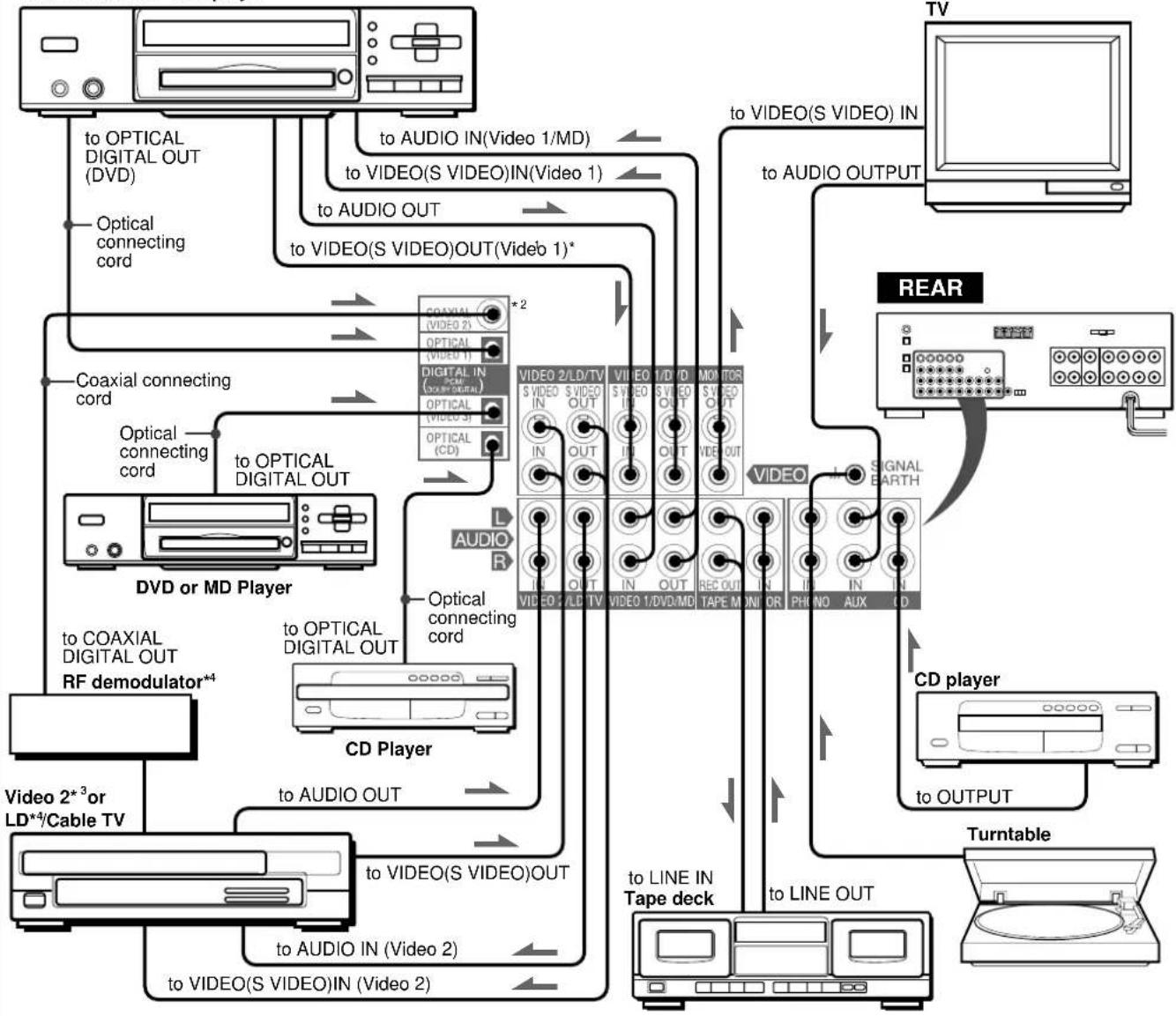
DVD or Video 1^*3 /MD player
①,② and ③ in the illustration correspond to the following details.

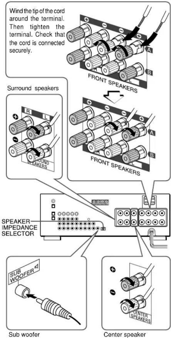
Connect front speakers (system A and/or B), a center speaker, surround speakers and subwoofer to the corresponding speaker terminals on the unit:
- the front speaker cords to the FRONT SPEAKERS terminals
- the center speaker cord to the CENTER SPEAKER terminals
- the surround speaker cords to the SURROUND SPEAKERS terminals.
- for more powerful bass, the sub woofer (with a built-in amplifier) cord to the SUB WOOFER jack
When connecting the sub woofer, be sure to select the "SUBW ON" (sub woofer on) mode (see page 5).
Speaker impedance
- Front and center speakers
Use the same impedance for both the front and center speakers. The SPEAKER IMPEDANCE SELECTOR on the rear should be set to the position that matches the impedance value of the front and center speakers.
When using 4 ohm speakers, set the selector to IMP:4Ω. When using 8 ohm speakers, set the selector to IMP:8Ω. Please unplug the AC cord before setting the selector.
- Surround speakers and sub woofer
The SPEAKER IMPEDANCE SELECTOR has no effect on the SURROUND SPEAKERS terminals and the SUB WOOFER jack. For the surround speakers and sub woofer, use speakers of 8 ohms or more.
Connecting ^+ to +, -to- terminals
To get the proper sound effect, the speaker terminals on the unit and the speaker should be connected with proper polarity; the + terminal on the unit should be connected to the + terminal on the speaker (and - to -).
NOTE
- Be sure to connect the speaker cords correctly as shown in the illustration on the right column. Improper connections can cause short circuits in the SPEAKER(S) terminals.
- Do not leave objects generating magnetism near the speakers.
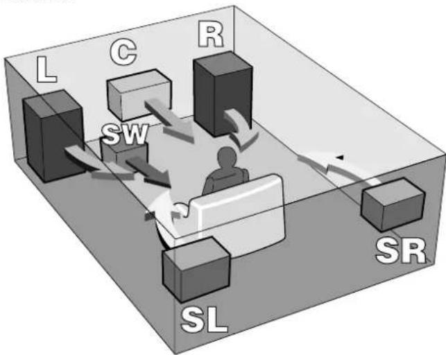
Front speakers
Position the speakers to make the most of DOLBY SURROUND, DTS SURROUND or DSP surround effect.
Front speakers (L/R)
Center speaker (C)
Position in the center of the two front speakers. In addition, position on or below the TV set, if connecting a TV set to the unit.
Surround speakers (SL/SR)
Place the surround speakers directly to the side of or slightly behind the listening area. Align them horizontally, about 1 meter (3.2 feet) above ear height.
Sub woofer (SW)
Place the sub woofer in any place between the two front speakers.
When connecting a sub woofer
Select "SUBW ON" mode.
-
Press the MANUAL SELECT button on the remote control once so that "SUBW OFF" appears on the display.
-
Within 4 seconds, press the TUNING (DOWN) button or turn the MULTI JOG to the left to display "SUBW ON." If a sub woofer is not connected, be sure to select "SUBW OFF."
Display "SUBW ON" in step 1 and press the TUNING (UP) button or turn the MULTI JOG to the right in step 2.
NOTE
Sound from the surround speakers or center speaker depends on the setting of DOLBY SURROUND, DTS SURROUND or DSP surround.
USING AC OUTLETS ON THE UNIT ②
The unit is equipped with AC outlets. You can use them once the unit is connected to an AC outlet on a wall.
SWITCHED: Electric current flows through it when the unit is turned on.
UNSWITCHED: Electric current always flows through it.
Do not connect equipment beyond their capacity (120 W, 1 A MAX. and TOTAL)
CONNECTING THE SUPPLIED ANTENNAS ③
Connect the FM antenna to the FM 75Ω terminals and the AM antenna to the AM LOOP terminals.
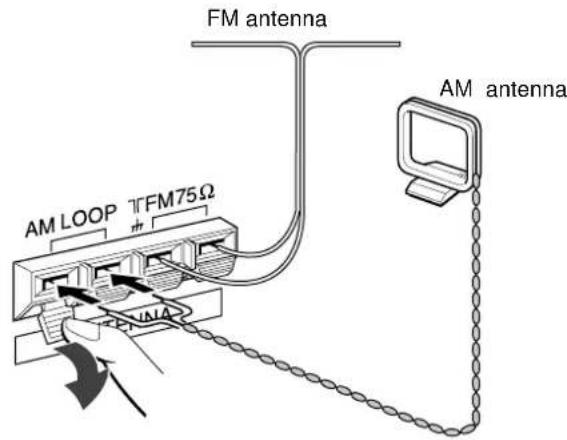
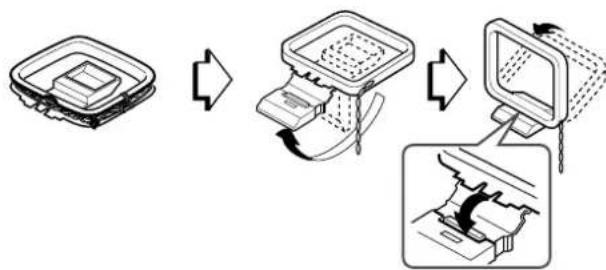
To stand the AM loop antenna on a surface
Fix the claw to the slot as shown in the illustration.
To position the antennas
FM feeder antenna:
Extend this antenna horizontally in a T shape and fix its ends to the wall.
AM loop antenna:
Position for the best reception.
NOTE
- Do not bring the FM antenna near metal objects or curtain rails.
- Do not bring the AM antenna near other external equipment, the unit itself, the AC power cord or speaker cords, as noise will be picked up.
- Do not unwind the AM loop antenna wire.
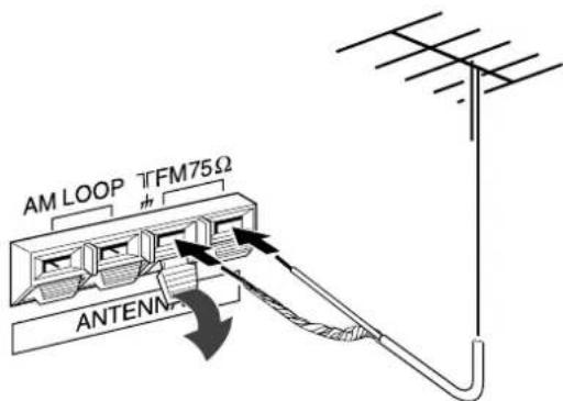
CONNECTING AN OUTDOOR ANTENNA
For better FM reception, use of an outdoor antenna is recommended. Connect the outdoor antenna to the FM 75Ω terminals.
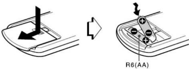
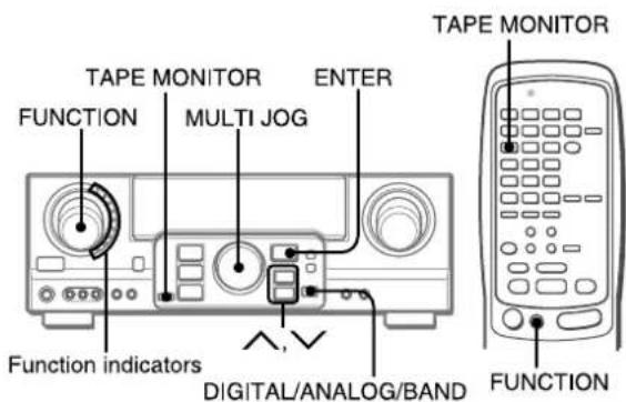
ABOUT THE REMOTE CONTROL
Inserting batteries
Detach the battery cover on the rear of the remote control and insert two R6 (size AA) batteries.
When to replace the batteries
The maximum operational distance between the remote control and the sensor on the unit should be approximately 5 meters (16 feet). When this distance decreases, replace the batteries with new ones.
Important
- The ENTER buttons on the remote control do not substitute for the ENTER button on the main unit. They are for operating AIWA DVD players or other audio/video equipment.
- In principal, the UP and DOWN buttons on the remote control substitute for the and buttons on the main unit except when selecting the TUNER function.
NOTE
- If the unit is not going to be used for an extended period of time, remove the batteries to prevent possible electrolyte leakage.
- The remote control may not operate correctly when:
- The line of sight between the remote control and the remote sensor in the display window is exposed to intense light, such as direct sunlight.
- Other remote controls are used nearby (those of a television, etc.)
Remote control operation
This remote control system allows you to operate other external equipment besides the AIWA receiver. For details of the remote control operation for other external equipment, see "REMOTE CONTROL" on page 20.
The following is an explanation on how to operate the AIWA receiver and the AIWA DVD players.
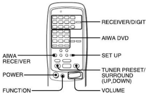
Each time this button is pressed, the sound source changes cyclically.
Tune in the station which has been preset on the receiver.
To go to a higher preset number, press the UP button. To go to a lower preset number, press the DOWN button.
This button is also used when adjusting the speaker level balance of DOLBY SURROUND, DTS SURROUND or DSP surround etc.
NOTE
It is not necessary to press the AIWA RECEIVER button each time you operate the AIWA receiver unless another mode has already been set. (See "REMOTE CONTROL" on page 20.)
Operating AIWA DVD players
You can control basic functions of AIWA DVD players with the remote control. In principle, the AIWA DVD buttons have the same function as those on the DVD players.
For more details, refer to the operating instructions of the player.
If the receiver cannot be operated with the remote control
Follow the steps below using the remote control.
The indicator on the top of the remote control blinks twice while pressing the button.
To turn the unit on
Operation is possible after four seconds. The VOL (volume) level or function name is displayed one after the other for the first four seconds.
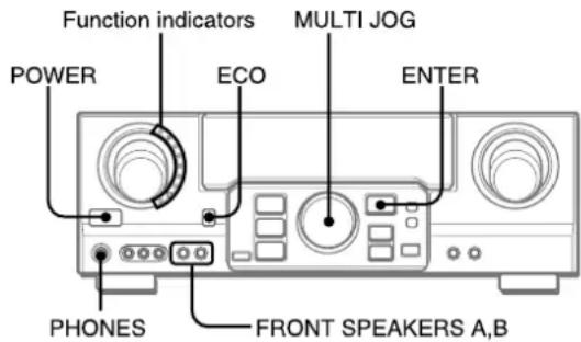
The selected function indicator lights up in red.
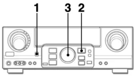
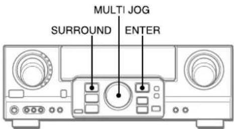
To change the brightness level of the display
1 Press the ECO button repeatedly until "DIM MODE" is displayed.
2 Within 4 seconds, press the ENTER button.
3 Within 4 seconds, turn the MULTI JOG to select the dimmer mode as below.
The mode will be automatically set after 4 seconds. It will also be set if the ENTER button is pressed within 4 seconds after step 3.

DIM-OFF: The normal display.
DIMMER 1: The illumination of the display is dimmer than usual.
DIMMER 2: The illumination of the display is dimmer than DIMMER 1. The function indicator turns off.
Using the headphones
Connect headphones to the PHONES jack with a standard stereo plug ( 6.3mm,1 / 4 inch). Be sure to set the FRONT SPEAKERS A and B buttons to OFF. Otherwise sound is output from the speakers.
NOTE
When the headphones are plugged in:
- The Dolby Pro Logic or DSP system is automatically canceled
- The Dolby Digital surround mode or the DTS surround mode is changed to the "2chSTEREO (2CH DOWNMIX)" mode
To select the front speaker system
To use speaker system A: Set the FRONT SPEAKERS A button to ON.
To use speaker system B: Set the FRONT SPEAKERS B button to ON.
To use both speaker systems: Set both the buttons to ON.
Set the button(s) to OFF to turn off the speaker system(s).
NOTE
As the front speaker systems A and B are connected in series:
- The sound will decrease slightly when using both speaker systems
- No sound can be heard if the FRONT SPEAKERS A and B buttons are set to ON when only one speaker system is connected
To turn the unit off, press the POWER button.
POWER ECONOMIZING (ECO) MODE
Setting this unit to the ECO mode reduces power consumption as below.
Initial setting of the ECO mode is ON.
- When the current time is set, the clock display disappears immediately.
- While the power is off, all the display lights turn off, and only the indicator on the left side of the display window lights in red.
To cancel the ECO mode
1 Press the ECO button to display ECO MODE while the unit is turned on.
2 Within 4 seconds, press the ENTER button.
3 Within 4 seconds, turn the MULTI JOG to select ECO OFF. The mode will be automatically set after 4 seconds. It will also be set if the ENTER button is pressed within 4 seconds after step 3.
CUSTOM AUDIOADJUSTMENT
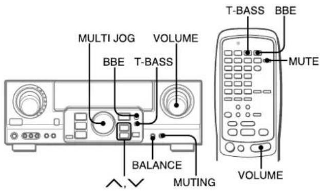
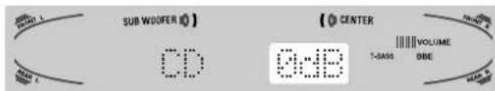
VOLUME CONTROL
Turn the VOLUME control on the unit, or press the VOLUME buttons on the remote control.
The volume level is shown on the display for four seconds. It can be adjusted between 0 and MAX (31). It flashes when set over the level of 27.
The volume level remains memorized even after the power is turned off. However, if the power is turned off when the volume is set to 17 or more, it is automatically set to 16 the next time the power is turned on.
To adjust the left/right balance of the front speakers
Press the BALANCE button to display "L/R 0dB". Then press the or button repeatedly or turn the MULTI JOG within four seconds.
Note that the front speaker balance for DOLBY SURROUND and DTS SURROUND is also changed.
To mute the sound temporarily
Press the MUTING (MUTE) button (-20 dB).
"MUTE ON" appears on the display for four seconds. While muting the sound, the selected function indicator flashes. Press the MUTING button again to restore the sound.
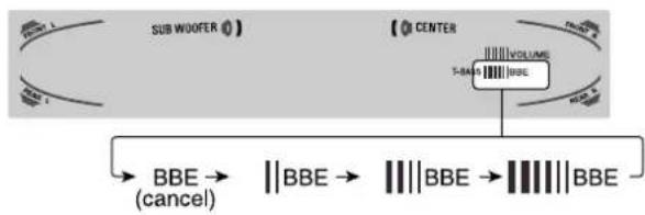
BBE SYSTEM
The BBE system enhances the clarity of high-frequency sound. Press the BBE button.
Each time it is pressed, the level changes. Select one of the three levels, or the off position to suit your preference.
NOTE
-
The BBE system is automatically canceled and cannot be turned on:
-
When the DIGITAL mode is selected
-
When the Dolby Pro Logic is turned on
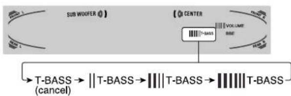
SUPERT-BASS SYSTEM
The T-BASS system enhances the realism of low-frequency sound.
Each time it is pressed, the level changes. Select one of the three levels, or the off position to suit your preference.
NOTE
Low-frequency sound may be distorted when the T-BASS system is used for a disc or tape in which low-frequency sound is originally emphasized. In this case, cancel the T-BASS system.
SOUND ADJUSTMENT DURING RECORDING
The output volume and tone of the speakers or headphones may be freely varied without affecting the level of the recording.
ELECTRONIC GRAPHIC EQUALIZER
This unit provides the following five different equalization modes.
ROCK: Powerful sound emphasizing treble and bass
POP: More presence in the vocals and midrange
JAZZ: Accented lower frequencies for jazz-type music
CLASSIC: Enriched sound with heavy bass and fine treble
BGM: Calm tone with suppressed bass and treble
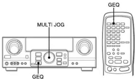
Press the GEQ (Graphic Equalizer) button, and turn the MULTI JOG until the desired equalization mode is displayed.
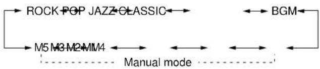
The GEQ modes are displayed cyclically as follows.
The selected mode name is displayed for four seconds, and the GEQ indicator lights up.
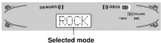
To cancel the selected mode
Press the GEQ button to display the GEQ mode name, and press the button again within 4 seconds. "GEQ OFF" appears on the display.
To select with the remote control
Press the GEQ button repeatedly until the desired equalization mode is displayed.
Five preset modes, the manual modes GEQ M1 to GEQ M5 and "GEQ OFF" can be selected.
SETTING NEW EQUALIZATION CURVES
Up to 5 equalization curves can be stored as the manual modes M1 to M5.
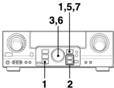
1 Press the GEQ button and press the ENTER button within 4 seconds.
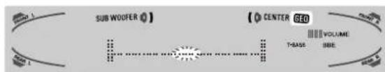
2 Press the or button to select a frequency. The level indicator of the selected frequency flashes.
3 Turn the MULTI JOG to adjust the level of the selected frequency.
4 Repeat steps 2 and 3 to make the desired equalization curve.
In steps 2 and 3, the unit returns to normal mode when no operation is made for about 8 seconds.
5 Within 8 seconds, press the ENTER button.
"GEQ M1" appears on the display.
6 Turn the MULTI JOG to select a preset number from M1 to M5.
7 Within 4 seconds, press the ENTER button.
The equalization curve is stored. The selected preset number and the equalization curve are displayed for a few seconds each.
To adjust the GEQ curve temporarily
Follow the steps from 1 to 4 above. The adjusted GEQ curve still remains before changing or canceling the GEQ mode.
To select the manual preset curve
Press the GEQ button, and turn the MULTI JOG until the desired manual preset number is displayed.
The DSP (Digital Signal Processor) surround circuits can recreate the effect of sounds reflected from walls or ceilings, to obtain the sound presence of real environments. The unit provides 30 DSP preset modes. Some of them are accompanied with the matching GEQ preset mode, and you can also select or turn off the GEQ to suit your preference.
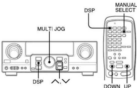
Press the DSP button, and turn the MULTI JOG or press the or button repeatedly until the desired DSP mode is displayed.
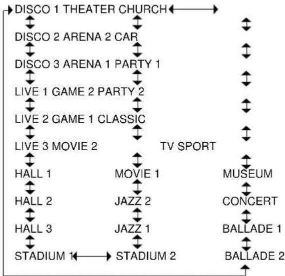
The selected mode name is displayed for four seconds, and the DSP indicator lights up. When the selected DSP mode is accompanied with the matching GEQ mode, the GEQ indicator lights up as well.

When the music source is monaural
The DSP system may not work effectively.
To cancel the selected mode
Press the DSP button to display the DSP mode name, and press the button again within 4 seconds. "DSP OFF" appears on the display. Even if canceling the selected DSP mode, the matching or selected GEO mode still remains.
To select with the remote control
1 Press the DSP button.
2 Within 4 seconds, press the UP or DOWN button repeatedly until the desired DSP mode is displayed. 30 preset modes can be selected.
To change the mode rapidly, hold down the UP or DOWN button.
To adjust the volume and balance of the surround speakers
Press the MANUAL SELECT button on the remote control three times to display "SUR 0dB" while the DSP system is turned on. Then press the (UP) or (DOWN) button repeatedly or turn the MULTI JOG within four seconds.
NOTE
The DSP surround system is automatically canceled and cannot be turned on:
- When the headphones are plugged in
- When the input signal is 96kHz
SELECTION OF AUDIO/VIDEO SOURCE
1 Select the program source.
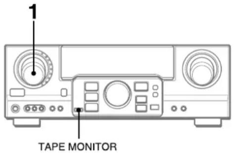
Turn the FUNCTION selector or press the TAPE MONITOR button. The selected function indicator lights in red.
| To listen to or watch | The indicator in red |
| Tape TAPE MONITOR | |
| Radio TUNER | |
| Record PHONO | |
| Compact disc CD | |
| Television, etc. | AUX |
| Video | VIDEO 1/DVD/MD,
VIDEO 2/LD/TV,VIDEO 3 |
| LD or Cable TV | VIDEO 2/LD/TV |
| MD or DVD | VIDEO 1/DVD/MD |
The function to be selected (except PHONO) depends on the equipment connected to the input terminals on the rear panel of the unit.
To select with the remote control
Press the TAPE MONITOR button or the FUNCTION button repeatedly.
NOTE
When using a turntable with a built-in equalizer amplifier, set the switch of the equalizer amplifier to off. See the instructions of the turntable for further information.
2 Start the selected program source.
3 Adjust the sound.
About the video source to the monitor or TV
The selected video source is indicated on the display and the video signal through the MONITOR VIDEO (SVIDEO) OUT jack is output on the TV.
To select the video source
1 Turn the FUNCTION to select PHONO, CD or AUX.
2 Press the ENTER button to display VIDEO 1.
3 Turn the MULTI JOG to select VIDEO 2 or VIDEO 3.
To change a displayed name for the VIDEO 1 andVIDEO2
When the VIDEO 1 function is selected,VIDEO 1 is displayed initially. It can be changed to DVD or MD.
Press the DIGITAL/ANALOG/BAND button while pressing the ENTER button, then release the ENTER button first.
The displayed name for the VIDEO 2 function can be changed toVIDEO2, LD or TV; while theVIDEO2 function is selected, press the DIGITAL/ANALOG/BAND button while pressing the ENTER button, then release the ENTER button first.
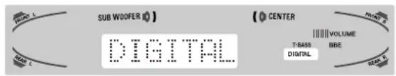
To select the "ANALOG" or "DIGITAL" (Dolby Digital or DTS surround) mode of the CD,VIDEO 1,VIDEO 2 orVIDEO 3 function
Press the DIGITAL/ANALOG/BAND button when the CD,VIDEO 1,VIDEO 2 orVIDEO 3 is selected. The selected mode "ANALOG" or "DIGITAL" appears on the display.
In the DIGITAL mode: Equipment connected to the OPTICAL DIGITAL IN terminal is selected as a source for the CD,VIDEO 1 orVIDEO 3 function, and equipment connected to the COAXIAL DIGITAL IN terminal for theVIDEO 2 function. The DIGITAL indicator lights in red.
In the ANALOG mode: Equipment connected to the CD,VIDEO 1/DVD/MD IN orVIDEO 3 terminals is selected as a source for the CD,VIDEO 1 orVIDEO 3 function, and equipment connected to theVIDEO 2/LD/TV terminals for theVIDEO 2 function.
NOTE
The "DIGITAL" mode changes to the "ANALOG," when pressing the TAPE MONITOR button.
When the "OVER LEVEL" indicator lights up
The unit is equipped with the OVER LEVEL indicator. When input analog signals from the connected equipment are too high to accept, the indicator lights on the right side of the display. In this case, adjust the input level as mentioned below so that the indicator disappears.
To adjust the sound level of the connected source
The input sensitivity level of each function can be adjusted (except the TUNER, CD(DIGITAL), VIDEO 1 (DIGITAL), VIDEO 2 (DIGITAL) and VIDEO 3 (DIGITAL) functions).
When the sound level of the connected source is higher or lower than that of the TUNER, adjust it as follows.
1 Select the function to be adjusted.
Turn the FUNCTION or press the TAPE MONITOR button and play the source.
Adjust the level so that the "OVER LEVEL" indicator does not light on the display.
- The level can be adjusted between -6dB (MIN) and +8dB (MAX) in 2dB steps. Adjust the level so that the sound is output at the same level as the TUNER.
The input sensitivity level of the TAPE MONITOR can be adjusted to 0dB or -6dB.
TO PLAY A DVD OR LD RECORDED IN DOLBY DIGITAL OR DTS SURROUND
This receiver is equipped with the Dolby Digital decoder and DTS decoder, and has the DIGITAL IN (both OPTICAL and COAXIAL) terminals. When a DVD or LD player is connected to the DIGITAL IN terminal of the receiver, you can enjoy theater-quality audio right in your home when playing discs recorded in Dolby Digital surround or DTS surround.
Before operation
- Check that the TAPE MONITOR is not selected. If the TAPE MONITOR is selected, press the TAPE MONITOR button so that "TAPE OFF" appears on the display.
- When connecting an LD player equipped with the AC-3 RF OUT terminal, use an RF demodulator unit. Also connect the analog AUDIO OUT terminals of the LD player to the receiver to play all the sources. For further information, refer to the instructions of the LD player.
The DVD (LD) player connected to the OPTICAL (COAXIAL) DIGITAL IN terminal is selected as a source.
2 Start playing the DVD (LD) recorded in Dolby Digital surround or DTS surround.
- The "DOLBY DIGITAL" indicator will light on the display when the bit stream of the Dolby Digital surround comes in the unit.
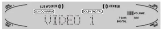
To select the Dolby Digital surround mode according to your speakers, see "SELECTING DOLBY SURROUND" on page 15.
- The "dts" indicator will light on the display when the bit stream of the DTS surround comes in the unit.
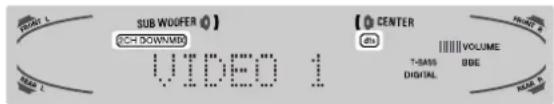
To select the DTS surround mode according to your speakers, see "SELECTING DTS SURROUND" on page 19.
NOTE
- While the TAPE MONITOR is selected and the TAPE MONITOR indicator turns red, "DIGITAL" cannot be selected.
- When headphones are plugged in, the Dolby Digital surround mode or DTS surround mode is automatically changed to "2chSTEREO" and the "2CH DOWNMIX" indicator lights on the display.
Even if the SURROUND button is pressed while the headphones are plugged in, the mode cannot be changed.
- This unit supports input signals of the Dolby Digital surround bit stream, DTS surround bit stream and linear PCM whose sampling frequency is 32kHz , 44.1kHz , 48kHz and 96kHz .
- When connecting some DVD players to the receiver through the DIGITAL IN terminals, noise may be heard in the DVD operation: e.g. searching a disc, skipping a chapter.
RECORDING AN AUDIO SOURCE
1 Select the program source to be recorded. Turn the FUNCTION.
2 Set the tape deck or MD recorder to the recording mode.
3 Start the selected program source.
To monitor recorded sound during recording (when the connected tape deck is a three-head system)
Press the TAPE MONITOR button. "TAPE ON" appears on the display for four seconds, and then the source name selected in step 1 comes back on. To cancel the tape monitor, press it again so that "TAPE OFF" appears.
NOTE
- Any sound control system has no effect on recording (see page 8).
- Input sound through the DIGITAL IN terminals cannot be recorded. When recording the sound from the DVD, CD, MD or LD player, connect the analog AUDIO OUT terminals of the player to the corresponding AUDIO IN terminals of the receiver.
The sound will be recorded in 2 ch stereo.
- When recording audio sources by the MD recorder connected to the VIDEO 1/DVD/MD AUDIO OUT terminals, the selected video source (see page 11) should be V2 or V3. Recording cannot be done while the V1 (VIDEO 1) is selected and displayed on the window.
- Input sound from the tape deck connected to the TAPE MONITOR IN terminals cannot be recorded.
To play a DTS audio CD
There are some audio CDs recorded in DTS surround like DVDs and LDs.
They will present you with a live-quality audio in your home.
1 Select the CD function.
2 Select the DIGITAL mode (see page 11).
The CD player connected to OPTICAL DIGITAL IN (CD) terminal is selected as a source.
3 Start playing the CD recorded in DTS surround.
To select the DTS surround mode, see page 19.
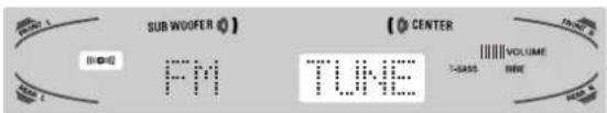
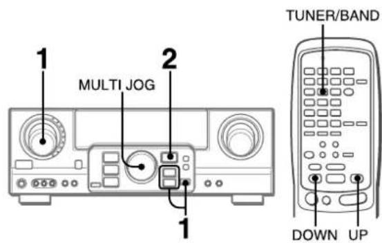
MANUAL TUNING
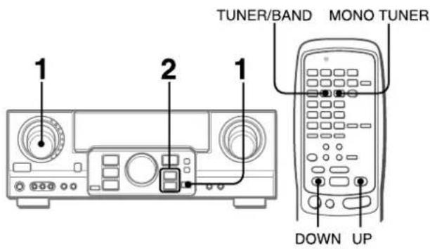
1 Turn the FUNCTION to select the TUNER function, and press the DIGITAL/ANALOG/BAND button repeatedly to select the desired band.

The display changes to frequency indications after indicating band and video source (V1, V2 or V3) for two seconds.
2 Press the or button to select a station.
Each time the button is pressed, the frequency changes. When a station is received, "TUNE" is displayed for two seconds. During FM stereo reception, (110) is displayed.
NOTE
To tune in to a station with the remote control, preset the stations first (see the next page). You can select the desired band with the TUNER/BAND button and tune in to the preset stations by pressing the UP or DOWN button.
To search for a station quickly (Auto Search)
Keep the or button pressed until the tuner starts searching for a station. After tuning in to a station, the search stops.
To stop the Auto Search manually, press the or button.
The Auto Search may not stop at stations with very weak signals.
When an FM stereo broadcast contains noise
Press the MONO TUNER button on the remote control so that "MONO" appears on the display.
Noise is reduced, although reception is monaural.
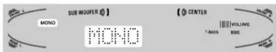
To restore stereo reception, press the button so that "STEREO" appears.
When the reception contains noise interference Move the unit away from other electrical appliances, especially digital audio devices, or turn off the appliances that generate noise signals.
To change the AM tuning interval
The default setting of the AM tuning interval is 10kHz step. If you use this unit in an area where the frequency allocation system is 9kHz step, change the tuning interval. Hold down the DIGITAL/ANALOG/BAND button and press the POWER button.
To reset the interval, repeat this procedure.
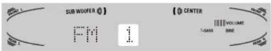
The unit can store a total of 32 preset stations. When a station is stored, a preset number is assigned to the station. Use the preset number to tune in to a preset station directly.
1 Turn the FUNCTION to select the TUNER function, and press the DIGITAL/ANALOG/BAND button repeatedly to select the desired band. Then press the or button to select a station.
2 Press the ENTER button to store the station.
A preset number assigned to the station, beginning from 1 in consecutive order for each band, appears in the display for two seconds.
3 Repeat steps 1 and 2.
No more stations will be stored and "FULL" appears if a total of 32 stations have already been stored for all the bands.
NOTE
When the AM tuning interval is changed, all preset stations are cleared. The preset stations have to be set again.
PRESET NUMBER TUNING
1 Turn the FUNCTION to select the TUNER function, and press the DIGITAL/ANALOG/BAND button repeatedly to select a band.
2 Turn the MULTI JOG to select a preset number.
To clear a preset station
Select the preset number of the station to be cleared. Then, press the ENTER button and press it again within four seconds. The preset numbers of all other stations in the band with higher numbers are decreased by one.
When using the remote control
1 Press the TUNER/BAND button to select the desired band.
2 Press the UP or DOWN button to select a preset number.
This unit is equipped with the Dolby Pro Logic decoder, Dolby Digital decoder and DTS decoder.
The unit and the center and surround speakers (standard) assure full-scale home theater sound. When playing back discs or video software that have been recorded in Dolby Pro Logic, Dolby Digital surround or DTS surround, astonishingly realistic sound surrounds the listener to create a new level of audio/visual entertainment.
Independent control of the five channels allows the listener to enjoy the same type of sound reproduction experienced in movie theaters. Voices are reproduced in the front and center sound field, while ambient sounds like cars and crowds are reproduced on all sides of the listener for an incredibly lifelike audio/video experience. Please read the following carefully to "tune" the system's output to match the characteristics of your listening space.
Check the following:
Before enjoying the DOLBY surround sound or DTS surround sound, adjust the speaker sound levels to the proper balance (see page 16).
Make sure the speakers are properly connected and positioned (see pages 4 and 5).
Make sure the TV set and video unit are properly connected (see page 3).
Make sure the disc and video tape, etc., support Dolby Pro Logic. Dolby Digital surround or DTS surround.
The optimal Dolby Digital surround and Dolby Pro Logic modes and settings depend on the type and placement of the speakers. It is recommended that the optional AIWA speakers should be used for all channels, for example, the SX-AVR2900 speaker system.
Check the current type and placement of your speakers and select the recommended mode accordingly.
The recommended mode
[Dolby Digital surround]
| Center speaker |
| Larger-size | Smaller-size | No speaker |
| Surround speaker (Rear speaker) | DOLBY D-WIDE | DOLBY D-NORMAL | PHANTOM |
| No surround speaker | 3 STEREO-WIDE | 3 STEREO-NORMAL | 2chSTEREO |
[Dolby Pro Logic]
| Center speaker |
| Larger-size | Smaller-size | No speaker |
| Surround speaker (Rear speaker) | PRO LOGIC-WIDE | PRO LOGIC-NORMAL | PHANTOM |
| No surround speaker | 3 STEREO-WIDE | 3 STEREO-NORMAL | - |
PHANTOM mode: Select this mode when the center speaker is not connected. All center channel signals are redistributed to the left and right channel speakers.
3 STEREO mode: Select this mode when the surround speakers are not connected.
TO SELECT A DOLBY SURROUND MODE
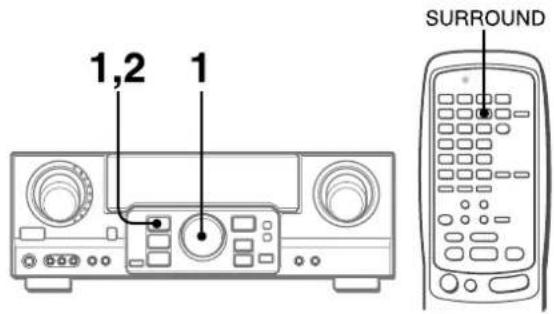
Preparations
- When selecting a Dolby Digital Surround mode, select theVIDEO 1 (DIGITAL),VIDEO 2 (DIGITAL) orVIDEO 3 (DIGITAL) function (see page 12) and play a disc recorded in Dolby Digital Surround before selecting the mode.
- When selecting a Dolby Pro Logic mode, select the function except CD(DIGITAL),VIDEO 1 (DIGITAL),VIDEO 2 (DIGITAL) andVIDEO 3 (DIGITAL).
The selected mode name appears on the display.
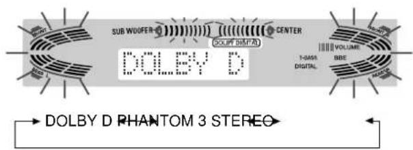
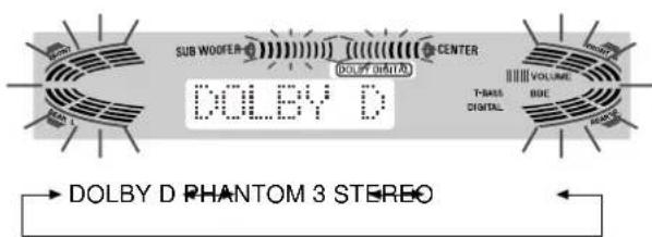
[Dolby Digital surround]
To select the 2chSTEREO mode, press the SURROUND button repeatedly until "2chSTEREO" appears.
NOTE
Select the Dolby Digital Surround mode while playing a source recorded in Dolby Digital Surround.
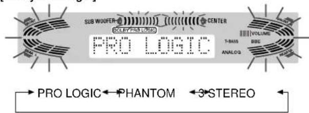
[Dolby Pro Logic]
"NORMAL" and "WIDE" appear one after the other.
When operating with the remote control
Press the SURROUND button repeatedly to select the mode, and hold it down to select the center speaker mode.
NOTE
- Depending on the sound source or listening condition, surround effect may not be obtained even when the Dolby Digital surround or Dolby Pro Logic is selected.
- The full Dolby Digital surround or Dolby Pro Logic effect cannot be obtained when using software not recorded in the Dolby Digital surround or Dolby Pro Logic system. In this case, use the DSP surround system instead (see page 10).
-
When headphones are plugged in:
-
The Dolby Pro Logic system is automatically canceled.
-
The Dolby Digital surround mode is automatically changed to "2chSTEREO."
-
While headphones are plugged in:
- The Dolby Pro Logic cannot be turned on.
- The Dolby Digital surround mode cannot be changed.
- The Dolby Pro Logic system is automatically canceled and cannot be turned on when the input signal is 96kHz .
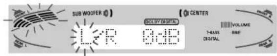
The unit is equipped with a built-in test signal generator called a noise sequencer for easy balance adjustment of all five channels. The sequencer outputs a noise signal that "travels" from channel to channel, enabling the simple adjustment of sound level to achieve the same apparent loudness, at your listening position, from each channel.
1 Select the Dolby Digital surround (except "2chSTEREO") or Dolby Pro Logic mode according to the current type and placement of your speakers. (See page 15.)
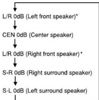
2 Press the MANUAL SELECT button on the remote control and hold it down for about two seconds until "L" of "L/R 0dB" starts to flash.
A noise signal is sent to each channel in turn as follows:
DOLBY D (PRO LOGIC) NORMAL or WIDE mode
PHANTOM mode

3 STEREONORMAL or WIDE mode

- "L" or "R" flashes to indicate one of the front speakers from which the noise signal is output.
To be continued
3 Adjust the sound level of the center and surround speakers.
While "CEN," "S-L" or "S-R" flashes in the display, press the UP or DOWN button on the remote control so that the sound level of the center or surround speakers matches that of the front speakers.
The balance of the front speakers can be adjusted as well while "L/R" is displayed.
NOTE
The or button on the main unit cannot be used.
NOTE
When adjusting the speaker level balance of the Dolby Digital surround, that of the Dolby Pro Logic is also changed and vice versa.
About the channels
The left and right speakers create the stereo effect.
The center speaker helps precise sound positioning over a broad sound field.
The rear-mounted surround speakers enhance the "depth" of the sound field.
To change the delay time of the surround speakers or center speaker when using the Dolby Digital surround or Dolby Pro Logic mode
While the Dolby Digital surround (except "2chSTEREO") or Dolby Pro Logic is activated, press the MANUAL SELECT button on the remote control repeatedly so that "CEN 0mS" or "SUR 5mS" (SUR 20mS) is displayed. Then, within 4 seconds, press the (UP) or (DOWN) button or turn the MULTI JOG. The delay time changes as shown below.
[Center speaker]
Adjust the delay time so that lines (voice in a movie) are heard clearly and naturally.
The center speaker delay time is initially set to 0 ms (milliseconds). It can be adjusted between 0 and 5 ms in 1 ms step.
![AIWA AVD97 - [Center speaker] - 1](/content/2026/03/435003/images/7e8e786a7494b824439383e78c29781c23c857902ed4bc002c6e00bfd0827c2c.jpg)
[Surround speakers]
Adjust the delay time to suite your preference.
Dolby Digital Surround
The speakers delay time is initially set to 5 ms. It can be adjusted between 0 and 15 ms in 5 ms steps.
Dolby Pro Logic
The speakers delay time is initially set to 20ms . It can be adjusted between 15 and 30ms in 5 ms steps.
NOTE
- When adjusting the delay time of the surround speakers or center speaker for the Dolby Digital surround, that of the Dolby Pro Logic is changed and vice versa.
- When the surround speakers delay time of the Dolby Digital surround is set to 0 ms (5 ms, 10 ms, or 15 ms), that of the Dolby Pro Logic is set to 15 ms (20 ms, 25 ms or 30 ms), and vice versa.
To adjust the speaker level balance while listening to the source
The speaker level balance can be changed after adjusting it with the noise sequencer. The balance can be changed whenever the Dolby Digital surround or Dolby Pro Logic system is activated.
1 Play a disc or video software recorded in Dolby Pro Logic or Dolby Digital surround.
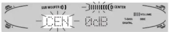
2 Press the MANUAL SELECT button on the remote control repeatedly so that "L/R," "CEN," "S-L" or "S-R" appears on the display.
3 Press the (UP) or (DOWN) button or turn the MULTI JOG while the speaker name to be adjusted is displayed.
The disc recorded in Dolby Digital surround contains special signals called LFE to enhance low frequency sound effect. The LFE signals are recorded in some particular parts on the disc and output from the connected sub-woofer to reproduce astonishingly powerful low sound.
The sound level of the LFE signals can be adjusted according to your speakers connected while the Dolby Digital surround is activated.
Preparation
- When connecting a sub-woofer, select "SUBW ON" (see page 5).
- Play a disc recorded in Dolby Digital Surround.
1 Press the (UP) or (DOWN) button and hold it down until "LFE" is displayed.
2 Press the (UP) or (DOWN) button repeatedly or turn the MULTI JOG to adjust the LFE level.
The unit is initially set to 0 dB (maximum) and can be adjusted as shown below.
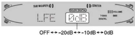
When selecting "SUBW OFF", the LFE signals are redistributed to other speakers.
ADJUSTING DYNAMIC RANGE
Dynamic range of the Dolby Digital surround sound can be adjusted. The unit is initially set to the "STD" (standard) mode.
1 While the Dolby Digital surround is activated, press the ENTER button and hold it down until "MID NIGHT THEATER" runs through on the display.
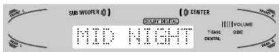
2 Press the (UP) (DOWN) button or turn the MULTI JOG to select the "MAX," "STD" or "MIN" mode.
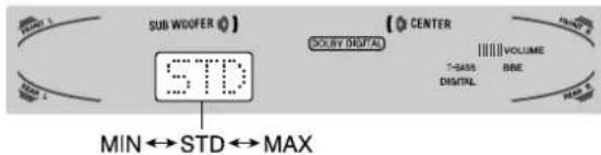
[MIN]
You can enjoy the full dynamic range sound like in the movie theater.
[STD]
Original position, when playing back in home, that is recommended by the software producers.
[MAX]
Select this mode when playing back at low volume. This is the mode used with the midnight setting.
The optimal DTS surround modes and settings depend on the type and placement of the speakers. It is recommended that the optional Aiwa speakers should be used for all channels, for example, the SX-AVR2900 speaker system. Check the current type and placement of your speakers and select the recommended mode accordingly.
The recommended mode
| Center speaker | No center speaker |
| Surround speaker (Rear speaker) | 5.1ch | 4 ch |
| No surround speaker | 3 STEREO | 2chSTEREO |
4 ch mode: Select this mode when the center speaker is not connected. All center channel signals are redistributed to the left and right channel speakers.
3 STEREO mode: Select this mode when the surround speakers are not connected.
TO SELECT A DTS SURROUND MODE
Preparation
When selecting a DTS surround, select the DIGITAL function and play a disc recorded in DTS surround before selecting the mode.
The selected mode name appears on the display.
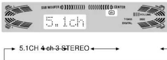
To select the 2chSTEREO mode, press the SURROUND button repeatedly until "2chSTEREO" appears.
Before playing a disc, adjust the speaker level balance in Dolby Digital or Dolby Pro Logic mode as described in page 16.
To adjust the balance while listening to the source, see the right column in page 17 and follow the steps 2 and 3. The delay time of the center and surround speakers cannot be adjusted in DTS surround mode.
NOTE
- Depending on the sound source or listening condition, surround effect may not be obtained even when the DTS surround is selected.
- The full DTS surround effect cannot be obtained when using software not recorded in the DTS surround system. In this case, use the DSP surround system instead (see page 10).
- When headphones are plugged in, DTS surround mode is automatically changed to "2chSTEREO."
- While headphones are plugged in, DTS surround mode cannot be changed.
TO LISTEN TO THE ORIGINAL DTS SOUND
When the DTS is appears on the display, all the sound settings can be canceled for DTS sound.
1 While the DTS surround is activated, press the ENTER button and hold it down until "BYPASS OFF" runs through on the display.
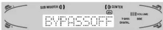
2 Press the ENTER button again to display "BYPASS ON."
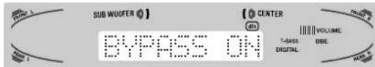
To restore the sound settings
Repeat steps 1 and 2 so that "BYPASS OFF" appears.
You can control basic functions of a TV, CABLE TV, VCR and CD player with this remote control.
TO ENTER THE ID CODE OF THE EXTERNAL EQUIPMENT
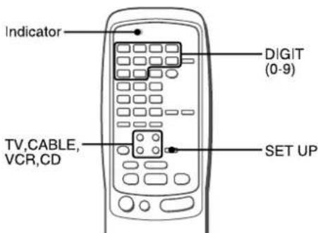
Before attempting to control them, be sure to enter the ID code of the external equipment to the remote control as follows.
1 Confirm the code number of the external equipment.
See the ID code list in the "APPENDIX" at the end of this manual.
2 Press either the TV, CABLE, VCR or CD button in the MODE SELECT area.
NOTE
When entering the ID code of a DSS satellite, press the CABLE button.
3 Press and hold the SET UP button for about 3 seconds.
Confirm that the indicator blinks twice while pressing the SET UP button.
4 Press four DIGIT buttons which correspond to the ID code of the external equipment.
For example, if your CD player is an AIWA unit, the required ID code is 0124 or 0157. In this case, press the DIGIT buttons in the order of "0," "1," "2" and "4" (or "0," "1," "5" and "7").
After the fourth DIGIT button is pressed, the indicator blinks twice indicating that the ID code is correct and is stored on the remote control.
To confirm the stored ID code
You can check the stored ID code by counting the indicator blinking.
1 Press either the TV, CABLE, VCR or CD button.
For example, to check the stored code for CD player, press CD.
2 Press and hold the SET UP button for about 3 seconds.
3 Press "9," "9" and "0."
4 Press "1," and count the indicator blinks.
For example, in the case that the stored ID is "0157." The indicator does not blink.
5 Press "2," and count the indicator blinks.
The indicator blinks once.
6 Press "3," and count the indicator blinks.
The indicator blinks five times.
7 Press "4," and count the indicator blinks.
The indicator blinks seven times.
1 Press any button in the MODE SELECT area (TV, CABLE, VCR or CD).
The remote control is ready to operate the selected mode equipment.
2 Press one of the buttons indicated above.
For the use of the 0 - 9 and the ENTER buttons, see the instruction manual supplied with the unit to be controlled.
Other buttons indicated above have the same function which you will find on the unit to be controlled.
NOTE
- Reenter the ID code of the external equipment after replacing the batteries of the remote control.
- If there are plural ID codes for external equipment in the "APPENDIX," try each number listed until you can control the external equipment.
ON SCREEN DISPLAY
The receiver provides an "On Screen Display" function to show the receiver settings on the TV screen. With the TV turned on, when you operate the receiver buttons or remote control buttons, the settings appear on the TV screen as well as the receiver display. The following are examples of the "On Screen Display."
When turning on the receiver, pressing the function buttons, or tuning in a station
On the right side of the screen, the setting results appear for 5 seconds.
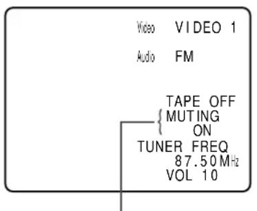
"MUTING ON" continues flashing until MUTING mode is set to off.
When pressing audio effect buttons such as SURROUND, DSP, GEQ, T-BASS, BBE and MANUAL SELECT
On the left side of the screen, the audio effect settings appear for 5 seconds.

When pressing CLOCK or SLEEP buttons on the remote control
On the left side of the screen, the timer setting and the present time appear for 5 seconds.
NOTE
- The receiver provides an "On Screen Display" function only when the TV is connected to the MONITOR VIDEO (SVIDEO) OUT jack.
- When connecting the SVIDEO OUT andVIDEO OUT terminals at the same time, the unit outputs the OSD data only through the SVIDEO OUT terminal.
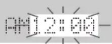
SETTING THE CLOCK

When the AC cord is connected for the first time, the clock on the display flashes.
Set the time as follows while the power is off.
1 Press the ENTER button.
The display becomes a little brighter.
2 Within 4 seconds, turn the MULTI JOG to designate the hour and the minute.
The time advances by turning it to the right, and decreases by turning it to the left.
The or button on the main unit is also available. Press the button repeatedly. To change the time rapidly in 10-minute steps, hold it down.
3 Press the ENTER button.
The clock starts from 00 seconds.
NOTE
When the clock is set for the first time after purchase
Everything on the display will clear.
This is because the power economizing mode of the unit is activated, and is not a malfunction.
The power economizing mode can be canceled. See page 7 for details.
To correct the current time
Press the POWER button to turn the unit off. Carry out steps 1 to 3 above.
To display the current time
Press the CLOCK button on the remote control. The clock is displayed for 4 seconds.
When the power is off in the power economizing mode, pressing the ENTER button on the unit also displays the current time for 4 seconds.
To switch to the 24-hour standard
Display the current time, and press the DIGITAL/ANALOG/BAND button on the unit within 4 seconds.
Repeat the same procedure to restore the 12-hour standard.
In the 12-hour standard, "AM 12:00" indicates midnight and "PM 12:00" indicates noon.
If the clock display flashes while the power is off
This is caused by a power interruption. The current time needs to be reset.
If power is interrupted for more than approximately 24 hours, all settings stored in memory after purchase need to be reset.
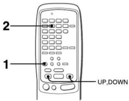
The receiver can be automatically turned off at a specified time.

The unit will be turned off after about 60 minutes.
To specify the time until the power is turned off
Press the UP or DOWN button repeatedly within four seconds after step 2.
Each time the button is pressed, the time changes between 5 and 240 minutes in 5-minute steps.
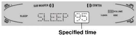
To check the time remaining until the power is turned off Press the SLEEP button once. The remaining time is displayed for four seconds.
To cancel the sleep timer
Press the SLEEP button twice so that "SLEEP" on the display disappears.
SPECIFICATIONS
FM tuner section
Tuning range 87.5 MHz to 108 MHz
Usable sensitivity 13.2 dBf
(IHF)
Antenna terminals 75 ohms (unbalanced)
AM tuner section
Tuning range 530kHz to 1710kHz (10 kHz step),
531 kHz to 1602 kHz (9 kHz step)
Usable sensitivity 350~ V / m
Antenna Loop antenna
Amplifier section
Power output [Stereo Mode]
Front
170 watts per channel, Min. RMS at 8
ohms, from 40Hz to 20kHz , with no
more than 0.9% Total Harmonic
Distortion
[Dolby Digital Surround or Dolby
Pro Logic Mode]
Front
120 watts per channel, Min. RMS at 8
ohms, from 40Hz to 20kHz , with no
more than 0.9% Total Harmonic
Distortion
Rear (Surround)
120 watts per channel, Min. RMS at 8
ohms, 1kHz with no more than 0.9%
Total Harmonic Distortion
Center
120 watts, Min. RMS at 8 ohms, 1
kHz, with no more than 0.9% Total
Harmonic Distortion
Total harmonic 0.08% (85 W, 1 kHz, 8 ohms, Front)
distortion
Inputs AUDIO IN
PHONO: 2.5mV ,adjustable (47
kohms)
AUX: 230mV
adjustable (47 kohms)
DIGITAL IN
COAXIAL (VIDEO 2):
OPTICAL (VIDEO 1):
OPTICAL (VIDEO 3):
OPTICAL (CD):
accept linear PCM signals
and bit stream of Dolby Digital
and DTS Surround (32 kHz, 44.1
kHz, 48 kHz and 96 kHz)
VIDEO IN: 1 Vp-p (75 ohms)
Outputs AUDIO OUT (REC OUT): 300mV (1
kohm)
VIDEO OUT (MONITOR): 1 Vp-p (75
ohms)
SUB WOOFER: 5.0 V
FRONT SPEAKERS IMP: 8 /4
selectable(front speakersA and B):
with the SPEAKER IMPEDANCE
SELECTOR set to 4 accepts
speakers of 4 ohms.
with the SPEAKER IMPEDANCE
SELECTOR set to 8Ω, accepts
speakers of 8 ohms or more.
surround speakers): accepts
speakers of 8 ohms or more
CENTER SPEAKER IMP: 8 /4
selectable
with the SPEAKER IMPEDANCE
SELECTOR set to 4 accepts
speaker of 4 ohms.
with the SPEAKER IMPEDANCE
SELECTOR set to 8 accepts
speaker of 8 ohms or more.
PHONES (stereo jack): accepts
headphones of 32 ohms or more
Muting -20 dB
General
Power requirements 120 V AC, 60 Hz
Power consumption 270 W
Power consumption in ECO OFF 60 W
standby mode ECO ON 1.5 W
Dimensions
(W·H·D)
(17. 6^1 / 8 . 15^7 / 8 in.)
Weight
12.5 kg (27 lb 9 oz.)
Specifications and external appearance are subject to change without notice.
BDE SYSTEM
The word "BBE" and the "BBE symbol" are trademarks of BBE Sound, Inc.
Under license from BBE sound, Inc.
Manufactured under license from Dolby Laboratories.
"Dolby", "Pro Logic" and the double-D symbol are trademarks of Dolby Laboratories. Confidential Unpublished Works. ©1992-
1997 Dolby Laboratories, Inc. All rights reserved.
- Manufactured under license from Digital Theater Systems, Inc.
US Pat. No. 5,451,942 and other world-wide patents issued and pending. "DTS" and "DTS Digital Surround" are trademarks of Digital Theater Systems, Inc. ©1996 Digital Theater systems, Inc. All Rights Reserved.
Occasional care and maintenance of the unit is needed to optimize the performance of your unit.
To clean the cabinet
Use a soft dry cloth.
If the surfaces are extremely dirty, use a soft cloth lightly moistened with mild detergent solution. Do not use strong solvents, such as alcohol, benzine or thinner as these could damage the finish of the unit.
TROUBLESHOOTING GUIDE
If the unit fails to perform as described in these Operating Instructions, check the following guide.
GENERAL
There is no sound.
Is the AC cord connected properly?
- Is there an incorrect connection? ( page 3, 4)
- There may be a short circuit in the speaker terminals.
Disconnect the AC cord, then correct the speaker connections.
- Was an incorrect function button pressed?
- Was the TAPE MONITOR button pressed?
- Are the FRONT SPEAKERS A and B buttons set correctly? ( page 7)
Sound is emitted from one speaker only.
- Is the BALANCE set appropriately?
- Is the other speaker disconnected?
Sound is heard at a very low volume.
- Has the MUTING button been pressed?
An erroneous display or a malfunction occurs.
Reset the unit as stated below.
TUNER SECTION
There is constant, wave-like static.
- Is the antenna connected properly? ( page 5)
Is the FM signal weak?
Connect an outdoor antenna.
The reception contains noise interference or the sound is distorted.
- Is the system picking up external noise or multipath distortion?
Change the orientation of the antenna.
Move the unit away from other electrical appliances.
To reset
If an unusual condition in the display window or malfunction occurs, reset the unit as follows.
1 Press the POWER button to turn off the power.
2 Press the POWER button while pressing the ENTER button.
Everything stored in memory after purchase is canceled.
If the power cannot be turned off in step 1 because of a malfunction, reset by disconnecting the AC cord and carry out step 2.
PARTS INDEX
Instructions about each part on the unit or remote control are indicated on the pages listed below.
| (in alphabetical order) |
| Parts Pages |
| AIWA RECEIVER 6, 22 |
| AUX 11 |
| BALANCE 8 |
| BBE 8, 21 |
| CD | 11, 20 |
| CHANNEL | 20 |
| CLOCK | 21 |
| DIGITAL/ANALOG/BAND | 11-14, 21 |
| DSP | 10, 21 |
| ECO | 7 |
| ENTER | 6, 7, 9, 11, 14, 18-21, 24 |
| FRONT SPEAKERS A, B | 7 |
| FUNCTION | 6, 11-14 |
| GEQ | 9, 21 |
| MANUAL SELECT (TEST) | 5, 10, 16, 17, 21 |
| MONO TUNER | 13 |
| MULTI JOG | 5, 7, 9, 10-12, 14-19, 21 |
| MUTING, MUTE | 8 |
| PHONES | 7 |
| PHONO | 11 |
| POWER | 6, 7, 13, 24 |
| RECEIVER/DIGIT | 6, 20 |
| SET UP | 6, 20 |
| SLEEP | 22 |
| SPEAKER IMPEDANCE |
| SELECTOR | 4 |
| SURROUND | 15, 16, 19, 21 |
| TAPE MONITOR | 11, 12 |
| T-BASS | 8, 21 |
| TUNER BAND | 13, 14 |
| TUNER PRESET/SURROUND | 6 |
| TUNING (DOWN) | 5, 6, 8-11, 13, 14, 17, 18, 21 |
| 22 |
| TUNING (UP) 5, 6, 8-11, 13, 14, 17, 18, 21, 22 |
| TV | 20 |
| VCR | 20 |
| VIDEO 1/DVD/MD | 11 |
| VIDEO 2/LD/TV | 11 |
| VIDEO 3 | 11 |
| VOLUME | 6, 8 |
ID CODES FOR TV
CÓDIGOS DE IDENTIFICACION PARA TELEVISION
CODES ID DE TELESEURS
| BRAND NAME
MARCA CÓDIGO DE
NOM DE MARQUE | ID CODE
IDENTIFICATION
CODE ID |
| A-Mark | 0003 |
| Abex | 0032 |
| Admiral | 0093, 0463 |
| Adventura 0046 | |
| Aiko | 0092 |
| Akai | 0030 |
| Alaron | 0179 |
| Ambassador | 0177 |
| America Action | 0180 |
| Ampro | 0751 |
| Anam 0180 | |
| Anam National | 0055 |
| AOC | 0003, 0019,
0030, 0052, 0185 |
| Archer | 0003 |
| Audiovox | 0003, 0092, 0180,
0451, 0623 |
| Baysonic | 0180 |
| Belcor 0019 | |
| Bell & Howell | 0016, 0154 |
| Bradford 0180 | |
| Brockwood | 0019 |
| Broksonic | 0003, 0236, 0463 |
| Candle | 0030, 0046, 0056,
0186 |
| Carnivale | 0030 |
| Carver | 0054 |
| Celebrity | 0000 |
| Cineral | 0092, 0451 |
| Citizen | 0030, 0039, 0046,
0056, 0060, 0092,
0186, 0280 |
| Clairtone | 0185 |
| Concerto | 0056 |
| Contec | 0180, 0185 |
| Craig 0180 | |
| Crosley | 0054 |
| Crown | 0039, 0180 |
| Curtis Mathes | 0016, 0030, 0039,
0047, 0051, 0054,
0056, 0060, 0093
0145, 0154, 0166,
0451, 0466 |
| CXC 0180 | |
| Daewoo | 0019, 0039, 0092,
0451, 0623, 0624 |
| Daytron 0019 | |
| Denon 0145 | |
| Dumont 0017, 0019 | |
| Dwin 0720, 0774 | |
| Electroband 0000, 0185 |
| Emerson 0019, 0038, | 0039, 0154, 0177, 0178, 0179, 0180, 0185, 0236, 0280, 0282, 0463, 0623, 0624 |
| Envision 0030 | |
| Fisher 0154, 0159 | |
| Fujitsu 0179, 0683 | |
| Funai 0171, 0179, 0180 |
| Futuretech 0180 | |
| GE 0021, 0027, 0047, | 0051, 0055, 0093, 0135, 0178, 0282, 0451 |
| Gibraltar 0017, 0019, 0030 |
| GoldStar 0001, 0019, | 0030, 0032, 0056, 0178 |
| Gradienté 0053, 0056 | |
| Grunpy 0179, 0180 | |
| Hallmark 0178 | |
| Harley Davidson | 0179 |
| Harman/ Kardon | 0054 |
| Harvard 0180 | |
| Hitachi | 0016, 0032, 0038, 0056, 0145, 0151 |
| Infinity | 0054 |
| Inteq | 0017 |
| Janeil | 0046 |
| JBL | 0054 |
| JCB | 0000 |
| JVC | 0053 |
| Kaypani | 0052 |
| KEC | 0180 |
| Kenwood | 0019, 0030 |
| Kloss | 0024, 0046 |
| KTV | 0030, 0039, 0180, 0185, 0280 |
| LG | 0056 |
| Logik | 0016 |
| Luxman | 0056 |
| LXI 0047, 0054, 0154, | 0156, 0178 |
| Magnavox | 0020, 0024, 0030, 0054, 0096, 0179, 0186, 0187, 0386 |
| Majestic | 0016 |
| Marantz | 0030, 0054 |
| Matsushita | 0250 |
| Megatron | 0003, 0145, 0178 |
| MEI | 0185 |
| Memorex 0016, 0056 | 0150, 0154, 0178, 0250, 0463 |
| MGA | 0019, 0030, 0150, 0178 |
| Midland | 0017, 0032, 0039, 0047, 0051, 0135 |
| Minutz | 0021 |
| Mitsubishi | 0019, 0093, 0150, 0178 |
| Motorola | 0055, 0093 |
| MTC | 0019, 0030, 0056, 0060, 0185 |
| Multitech | 0180 |
| NAD 0156, 0166, 0178 | |
| NEC 0019, 0030, 0056, | 0497 |
| Nikko | 0030, 0092, 0178 |
| Noshi | 0018 |
| NTC | 0092 |
| Onwa 0180 | |
| Optimus 0154, 0166, | 0250 |
| Optonica | 0093, 0165 |
| Orion | 0179, 0236, 0463 |
| Panasonic | 0051, 0055, 0250 |
| Penney | 0003, 0018, 0019, 0021, 0027, 0030, 0032, 0039, 0047, 0051, 0056, 0060, 0135, 0156, 0178 |
| Philco | 0019, 0020, 0030, 0054, 0096, 0145, 0463 |
| Philips | 0054 |
| Pilot | 0019, 0030, 0039 |
| Pioneer | 0038, 0166 |
| Portland | 0019, 0039, 0092 |
| Prism | 0051 |
| Proscan | 0047 |
| Proton | 0003, 0052, 0178, 0466 |
| Pulsar 0017, 0019 | |
| Quasar 0051, 0055, | 0165, 0250 |
| Radio Shack 0019, 0030, 0032, 0039, 0047, 0056, 0154, 0165, 0178, 0180 |
| RCA 0018, 0019, 0038, 0047, 0051, 0090, 0093, 0135, 1447 |
| Realistic 0019, 0030, 0032, 0039, 0056, 0154, 0165, 0178, 0180 |
| Rhapsody 0185 | |
| Runco 0017, 0030, 0497, 0603 | |
| Sampo 0030, 0032, 0039, 0052 | |
| Samsung 0019, 0030, 0032, 0056, 0060, 0178 | |
| Samsux 0039 | |
| Sansei 0451 | |
| Sansui 0463 | |
| Sanyo 0154, 0159 | |
| Scimitsu 0019 | |
| Scotch 0178 | |
| Scott 0019, 0178, 0179, 0180, 0236 | |
| Sears 0047, 0054, 0056, 0154, 0156, 0159, 0171, 0178, 0179 | |
| Semivox 0180 | |
| Semp 0156 | |
| Sharp 0039, 0093, 0165, 0386 | |
| Shogun 0019 | |
| Signature 0016 | |
| Simpson 0186, 0187 | |
| Sony 0000, 0080 | |
| Sounddesign | 0178, 0179, 0180, 0186 |
| Spectricon | 0003 |
| Squareview | 0171 |
| SSS | 0019, 0180 |
| Starlite | 0180 |
| Supre-Macy | 0046 |
| Supreme | 0000 |
| Sylvania | 0020, 0030, 0054, 0096 |
| Symphonic | 0171 |
| Tandy 0093 | |
| Tatung | 0003, 0055 |
| Technics 0051, 0250 | |
| Technol Ace | 0179 |
| Techwood 0003, 0051 | , 0056 |
| Teknika | 0016, 0019, 0039, 0054, 0056, 0060, 0092, 0150, 0179, 0180, 0186 |
| Telefunken | 0056 |
| TMK 0056, 0177, 0178 | |
| Toshiba 0060, 0154, 0156 | |
| Tosonic | 0185 |
| Totevision | 0039 |
| Universal | 0027 |
| Vector Research | 0030 |
| Victor | 0053 |
| Vidikron 0054 | |
| Vidtech | 0019, 0178 |
| Viking | 0046 |
| Wards | 0016, 0019, 0020, 0021, 0027, 0030, 0054, 0056, 0080, 0096, 0165, 0178, 0179 |
| White Westinghouse | 0463, 0623, 0624 |
| Yamaha 0019, 0030 | |
| Zenith 0016, 0017, 0092, 0463, 0624 | |
| Zonda | 0003 |
ID CODES FOR CABLE TV CÓDIGOS DE IDENTIFICACION PARA CABLEVisión CODES ID DE DECODEURS
| BRAND NAME ID CODE
MARCA CÓDIGO DE
NOM DE MARQUE | IDENTIFICATION
CODE ID |
| ABC 0001, 0003, 0007 | 7,
0008, 0011, 0013,
0014, 0017 |
| Allegro 0153, 0315 | |
| Americast 0899 | |
| Antronix 0022, 0207 | |
| Archer 0022, 0153, 0207 | 207,
0797 |
| BBT 0267 | |
| Belcor 0056 | |
| Bell & Howell 0014 | |
| Bell South 0899 | |
| Cable Star 0056 | |
| Cabletenna 0022 | |
| Cableview 0022 | |
| Century | 0153 |
| Citizen | 0153, 0315 |
| Colour Voice | 0025, 0031 |
| Comtronics | 0040 |
| Contec | 0019 |
| Digi | 0637 |
| Eastern | 0002 |
| Emerson | 0797 |
| Everquest 0015, 0040 | |
| Focus | 0400 |
| Garrard | 0153 |
| GC Electronics | 0056, 0207 |
| Gemini | 0015, 0797 |
| General Instrument | 0011, 0276, 0476,
0810 |
| GoldStar | 0040, 0144 |
| Goodmind | 0779 |
| Hamlin 0009, 0020, 0334,
0259 | |
| Hitachi | 0011 |
| Hytex | 0007 |
| Jasco | 0015, 0153, 0315 |
| Jerrold | 0003, 0011, 0012,
0014, 0015, 0024,
0276, 0476, 0810 |
| Linsay 0440 | |
| Magnavox 0027 | |
| Memorex | 0000 |
| Movie Time 0063, 0156 |
| Novaplex | 0618 |
| NSC | 0063, 0156 |
| Oak | 0007, 0019 |
| Optimus 0021 | |
| Panasonic | 0000, 0021, 0107 |
| Panther | 0637 |
| Paragon 0000 | |
| Philips 0025, 0027, 0031, 0153 |
| Pioneer | 0023, 0144, 0533, 0877 |
| Popular Mechanics | 0400 |
| Pulsar 0000 | |
| Quasar | 0000 |
| Radio Shack | 0015, 0315, 0797, 0883 |
| RCA | 0021 |
| Realistic 0207 | |
| Recoton 0400 | |
| Regal | 0020, 0259 |
| Regency | 0002 |
| Rembrandt | 0011 |
| Runco | 0000 |
| Samsung | 0040, 0144 |
| Scientific Atlanta | 0008, 0017, 0477, 0877 |
| Seam | 0510 |
| Signal | 0015, 0040 |
| Signature | 0011 |
| SL Marx 0040 | |
| Sprucer | 0021 |
| Starcom 0003, 0015 | |
| Stargate | 0015, 0040, 0797 |
| Starquest | 0015 |
| Sylvania | 0001 |
| Tandy | 0258 |
| TeleCaption | 0221 |
| Teleview | 0040 |
| Texscan 0001 | |
| TFC 0310 | |
| Timeless | 0418 |
| Tocom 0012, 0013 | |
| Toshiba | 0000 |
| Tusa | 0015 |
| TV86 | 0063 |
| Unika | 0022, 0153, 0207 |
| United Artists | 0007 |
| Universal | 0022, 0056, 0153, 0191, 0207 |
| Viewstar | 0027, 0063, 0258 |
| Zenith | 0000, 0054, 0525, 0899 |
| Zentek | 0400 |
| BRAND NAME ID CODE
MARCA CÓDIGO DE
NOM DE MARQUE | IDENTIFICATION
CODE ID |
| Admiral 0048, 0209 | |
| Adventura 0000 | |
| Aiko 0278 | |
| Aiwa 0000, 0037, 0307 | 7,
0406, 0436, 0468,
0557 |
| Akai 0041, 0061, 0106 | |
| American Action 0278 | |
| American High 0035 | |
| Asha 0240 | |
| Audiovox 0037 | |
| Beaumark 0240 | |
| Bell & Howell 0104 | |
| Broksonic 0002, 0121 | 0184,
0209, 0479 |
| Calix | 0037 |
| Canon | 0035 |
| Capehart | 0020 |
| Carver | 0081 |
| CCE | 0072, 0278 |
| Cineral | 0278 |
| Citizen | 0037, 0278 |
| Colt | 0072 |
| Craig | 0037, 0047, 0072,
0240, 0271 |
| Curtis Mathes | 0035, 0041, 0060,
0162 |
| Cybernex | 0240 |
| Daewoo | 0020, 0045, 0278,
0561 |
| Daytron | 0020 |
| Denon | 0042 |
| Dynatech | 0000 |
| Electrohome | 0037 |
| Electrophonic | 0037 |
| Emerex 0032 | |
| Emerson 0000, 0002, | 0036,
0037, 0043, 0061,
0068, 0121, 0184,
0208, 0209, 0212
0278, 0479, 0561 |
| Fisher | 0047, 0054, 0066,
0104 |
| Fuji | 0033, 0035 |
| Funai | 0000 |
| Garrard | 0000 |
| GE | 0035, 0048, 0060, 0202, 0240 |
| Go Video | 0432, 0526 |
| GoldStar | 0037, 0038 |
| Gradiente 0000, 0008 | |
| Harley Davidson | 0000 |
| Harman/Kardon | 0038, 0081 |
| Harwood 0068, 0072 | |
| Headquarter | 0046 |
| HI-Q | 0047 |
| Hitachi | 0000, 0041, 0042, 0105 |
| Hughes Network Systems | 0042 |
| Jensen | 0041 |
| JVC 0008, 0041, 0067 | |
| KEC | 0037, 0278 |
| Kenwood | 0038, 0041, 0067 |
| KLH 0072 | |
| Kodak | 0035, 0037 |
| Lloyd's | 0000, 0208 |
| Logik | 0072 |
| LXI | 0037 |
| Magnasonic | 0278 |
| Magnavox 0000, 0035 | 0039, 0081, 0110, 0149 |
| Magnin | 0240 |
| Marantz | 0035, 0081 |
| Marta | 0037 |
| Matsushita | 0035, 0162, 0454 |
| MEI | 0035 |
| Memorex | 0000, 0035, 0037, 0039, 0046, 0047, 0048, 0104, 0209, 0240, 0307, 0454, 1162 |
| MGA 0043, 0061, 0240 | |
| MGN Technology | 0240 |
| Minolta | 0042, 0105 |
| Mitsubishi | 0043, 0048, 0061, 0067 |
| Motorola | 0035, 0048 |
| MTC 0000, 240 | |
| Multitech | 0000, 0072 |
| NEC | 0038, 0041, 0067, 0104 |
| Nikko | 0037 |
| Nikon | 0034 |
| Nobilex | 0240 |
| Olympus | 0035 |
| Optimus 0037, 0048, | 0104, 0162, 0432, 0454, 1162 |
| Optonica | 0062 |
| Orion | 0002, 0184, 0209, 0479 |
| Panasonic | 0035, 0077, 0162, 0225, 0454, 0616, 1162 |
| Penney | 0035, 0037, 0038, 0042, 0054, 0240 |
| Pentax | 0042, 0105 |
| Philco | 0035, 0209, 0479 |
| Philips | 0035, 0062, 0081, 0110, 0618 |
| Pilot 0037 | |
| Pioneer | 0067 |
| Portland | 0020 |
| Profitronic | 0240 |
| Proscan | 0060, 0202 |
| Protec | 0072 |
| Pulsar | 0039 |
| Quarter | 0046 |
| Quartz | 0046 |
| Quasar | 0035, 0077, 0162, 0454, 1162 |
| Radio Shack | 0000 |
| Radix | 0037 |
| Randex | 0037 |
| RCA | 0035, 0042, 0048, 0060, 0077, 0105, 0106, 0149, 0202, 0240 |
| Realistic 0000, 0035, | 0037, 0046, 0047, 0048, 0062, 0066, 0104 |
| ReplayTV 0614, 0616 | |
| Ricoh | 0034 |
| Runco | 0039 |
| Samsung | 0045, 0240 |
ID CODES FOR CD PLAYER
This equipment has been tested and found to comply with the limits for a Class B digital device, pursuant to Part 15 of the FCC Rules. These limits are designed to provide reasonable protection against harmful interference in a residential installation.
This equipment generates, uses, and can radiate radio frequency energy and, if not installed and used in accordance with the instructions, may cause harmful interference to radio communications. However, there is no guarantee that interference will not occur in a particular installation. If this equipment does cause harmful interference to radio or television reception, which can be determined by turning the equipment off and on, the user is encouraged to try to correct the interference by one or more of the following measures:
- Reorient or relocate the receiving antenna.
- Increase the separation between the equipment and receiver.
- Connect the equipment into an outlet on circuit different from that to which the receiver is connected.
- Consult the dealer or an experienced radio/TV technician for help.
CAUTION
Modifications or adjustments to this product, which are not expressly approved by the manufacturer, may void the user's right or authority to operate this product.
ADVERTENCIA
PARA REDUCIR EL RIESGO DE INCENDIOS O SACUDIDAS ELECTRICAS, NO EXPONGA Este APARATO A LA LLUVIA NI A LA HUMEDAD.

[Dolby Digital surround]
| Altavoz central |
| Más grande | Más(PC)pequeño | Sin altavoz |
| Altavoces perimétricos(altavoces traseros) | DOLBY D-WIDE | DOLBY D-NORMAL | PHANTOM |
| Sin altavocesperimétricos | 3 STEREO-WIDE | 3 STEREO-NORMAL | 2chSTEREO |
[Dolby Pro logic]
| Altavoz central |
| Más grande | Más(PC)pequeño | Sin(PC)altavoz |
| Altavoces perimétricos(altavoces traseros) | PROLOGIC-WIDE | PROLOGIC-NORMAL | PHANTOM |
| Sin altavocesperimétricos | 3 STEREO-WIDE | 3 STEREO-NORMAL | - |
AUX: 230mV
ajustable (47 kiloohmios)
DIGITAL IN
COAXIAL (VIDEO 2):
OPTICAL (VIDEO 1):
OPTICAL (VIDEO 3):
OPTICAL (CD):
[Dolby Digital surround]
| Enceinte centrale |
| Grande dimension | Petite dimension | Sans enceinte |
| Enceintes surround(enceintes arrière) | DOLBY D-WIDE | DOLBY D-NORMAL | PHANTOM |
| Sans enceintes surround | 3 STEREO-WIDE | 3 STEREO-NORMAL | 2chSTEREO |
[Dolby Pro Logic]
| Enceinte centrale |
| Grande dimension | Petite dimension | Sans enceinte |
| Enceintes surround(enceintes arrière) | PROLOGIC-WIDE | PROLOGIC-NORMAL | PHANTOM |
| Sans enceintes surround | 3 STEREOWIDE | 3 STEREONORMAL | - |
[Dolby Digital surround]
Distorsion harmonique 0,08% (85 W, 1 kHz, 8 ohms,
AUX: 230mV
réglable (47 kohms)
DIGITAL IN
COAXIAL (VIDEO 2):
OPTICAL (VIDEO 1):
OPTICAL (VIDEO 3):
OPTICAL (CD):
Digital et DTS Surround (32 kHz,