
AJHVF21G - Camcorder PANASONIC - Free user manual and instructions
Find the device manual for free AJHVF21G PANASONIC in PDF.
| Product type | HD electronic viewfinder for professional camcorder |
| Brand | Panasonic |
| Model | AJ-HVF21G |
| Image tube | 2.0-inch high-resolution monochrome |
| Image system | 1080 lines, 50/60 frames selectable |
| Power supply | 12 V DC supplied by camera |
| Power consumption | 3.8 W (AJ-HVF21G) |
| Dimensions (W × H × D) | 240 mm × 80 mm × 206 mm |
| Weight | 750 g |
| Operating temperature | 0 °C to 40 °C |
| Permissible humidity | 85% max (without condensation) |
| External adjustment controls | Brightness (BRIGHT), Contrast (CONTRAST), Peaking (PEAKING) |
| Switches | TALLY (HIGH/OFF/LOW), ZEBRA (ON/OFF) |
| Diopter adjustment | Yes, via adjustment ring |
| Mounting | Standard sliding rail or optional mounting module (VYQ1818) |
| Camera compatibility | AJ-HDX400, AJ-HDX400P, AJ-HDC27H, AJ-HDC27HP, AJ-HDC27HE, AJ-HDC27HMC (standard rail) ; AJ-HDC20A, AJ-HDC20AP, AJ-HDC27F, AJ-HDC27FP, AJ-HDC27FE, AJ-HDC27FMC (module) |
| Optional microphone | AJ-MC700P or AJ-MC900G (sold separately) |
| Safety | Do not expose to rain or moisture; do not disassemble (internal high voltage) |
| Maintenance - Cleaning the mirror | Use a blower; do not wipe the treated surface |
| Standards (Canada) | Complies with Canadian Class A NMB-003 |
Frequently Asked Questions - AJHVF21G PANASONIC
User questions about AJHVF21G PANASONIC
0 question about this device. Answer the ones you know or ask your own.
Ask a new question about this device
Download the instructions for your Camcorder in PDF format for free! Find your manual AJHVF21G - PANASONIC and take your electronic device back in hand. On this page are published all the documents necessary for the use of your device. AJHVF21G by PANASONIC.
USER MANUAL AJHVF21G PANASONIC
Before operating this product, please read the instructions carefully and save this manual for future use.
- TO REDUCE THE RISK OF FIRE OR SHOCK HAZARD, DO NOT EXPOSE THIS EQUIPMENT TO RAIN OR MOISTURE.
- TO REDUCE THE RISK OF FIRE OR SHOCK HAZARD, KEEP THIS EQUIPMENT AWAY FROM ALL LIQUIDS. USE AND STORE ONLY IN LOCATIONS WHICH ARE NOT EXPOSED TO THE RISK OF DRIPPING OR SPLASHING LIQUIDS, AND DO NOT PLACE ANY LIQUID CONTAINERS ON TOP OF THE EQUIPMENT.
Operating precaution
Operation near any appliance which generates strong magnetic fields may give rise to noise in the video and audio signals. If this should be the case, deal with the situation by, for instance, moving the source of the magnetic fields away from the unit before operation.
Caution:
- The interior of this product contains high-voltage components. Do not disassemble the product.
- Do not point the eyepiece directly at the sun.
Precautions for Use (For USA)
This device complies with part 15 of the FCC Rules. Operation is subject to the following two conditions:
(1) This device may not cause harmful interference, and (2) this device must accept any interference received, including interference that may cause undesired operation.
FCC Note:
This equipment has been tested and found to comply with the limits for a class A digital device, pursuant to Part 15 of the FCC Rules. These limits are designed to provide reasonable protection against harmful interference when the equipment is operated in a commercial environment. This equipment generates, uses, and can radiate radio frequency energy, and if not installed and used in accordance with the instruction manual, may cause harmful interference to radio communications. Operation of this equipment in a residential area is likely to cause harmful interference in which case the user will be required to correct the interference at his own expense.
Warning:
To assure continued FCC emission limit compliance, the user must use only shielded interface cables when connecting to external units. Also, any unauthorized changes or modifications to this equipment could void the user's authority to operate it.
Notice (U.S.A.only):
This product utilizes both a Cathode Ray Tube (CRT) and other components that contain lead.
Disposal of these materials may be regulated in your community due to environmental considerations.
For disposal or recycling information, please contact your local authorities, or the Electronics Industries Alliance:
Notice (For Canada)
THIS CLASS A DIGITAL APPRATUS COMPLIES WITH CANADIAN ICES-003.

indicates safety information.
Contents
Features 3
Parts and Their Functions 3
For cameras compatible with the standard slide rail 6
Mounting the Viewfinder 6
Adjusting the viewfinder's left-right position 7
Adjusting the viewfinder's front-back position 7
Detaching the Viewfinder 8
For cameras compatible with the mounting unit 9
Mounting the Viewfinder 10
Detaching the Viewfinder 10
Position Adjustment 11
Diopter Adjustment 12
Screen Adjustment 12
Detaching the Eyepiece 13
Mounting the Microphone 14
Specifications 15
Features
- The high-resolution CRT delivers superb picture sharpness, making focusing easier.
- The low-flare CRT makes the screen clear and easy on the eyes.
- The large eyepiece aperture makes it possible to see the screen even when holding the viewfinder at some distance from your eye.
The eyepiece is easily detachable. - The image system can be switched between 1080/60 fields and 1080/50 fields depending on the control signal from the camera. (AJ-HVF21G only)
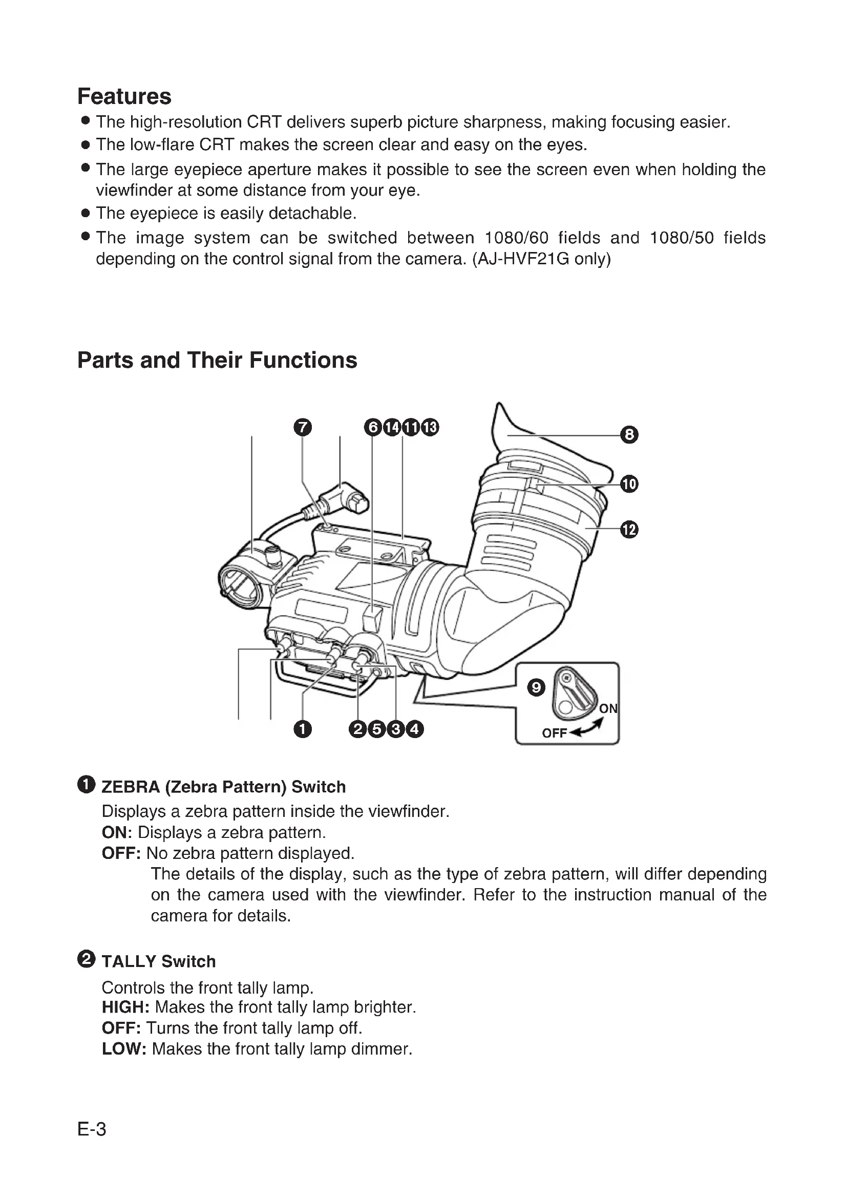
Parts and Their Functions
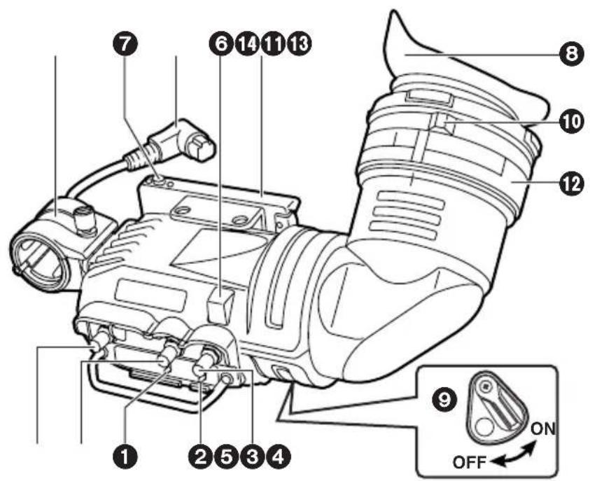
ZEBRA (Zebra Pattern) Switch
Displays a zebra pattern inside the viewfinder.
ON: Displays a zebra pattern.
OFF: No zebra pattern displayed.
The details of the display, such as the type of zebra pattern, will differ depending on the camera used with the viewfinder. Refer to the instruction manual of the camera for details.
TALLY Switch
Controls the front tally lamp.
HIGH: Makes the front tally lamp brighter.
OFF: Turns the front tally lamp off.
LOW: Makes the front tally lamp dimmer.
Parts and Their Functions
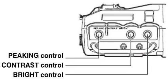
PEAKING Knob
Adjusts the outlines of the images in the viewfinder to make focusing easier. The setting of this control has no effect on the output signal of the camera.
CONTRAST Knob
Adjusts the contrast of the screen inside the viewfinder. The setting of this control has no effect on the output signal of the camera.
BRIGHT (Brightness) Knob
Adjusts the brightness of the screen inside the viewfinder. The setting of this control has no effect on the output signal of the camera.
Front Tally Lamp
Lights when the camera is shooting and the TALLY switch is set to HIGH or LOW.
Also, flashes on and off as a warning indication, in the same manner as the REC lamp, inside the viewfinder.
The brightness of the front tally lamp is controlled by the setting of the TALLY switch (HIGH or LOW).
Viewfinder stopper
This is used to attach and remove the viewfinder.
Eyepiece
Back Tally Lamp
Lights when the camera is shooting. Also, flashes on and off as a warning indication, in the same manner as the REC lamp inside the viewfinder.
The back tally lamp is hidden when the lever is in the OFF position.
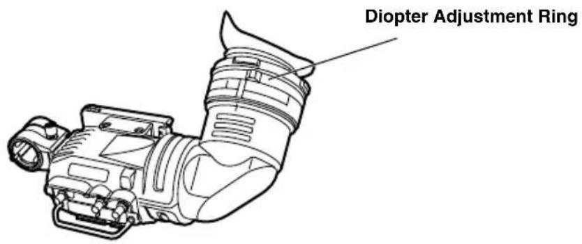
Diopter Adjustment Ring
Adjust this control to match the vision of the person using the camera so that the image on the screen in the viewfinder is as clear as possible.
1 Connection Plug
Lock Ring
Microphone Holder
1 Slide rail
Parts and Their Functions
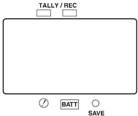
Internal LEDs
The lamp and picture tube indications will differ depending on the camera used with the viewfinder.
Refer to the instruction manual of the camera for details.
For cameras compatible with the standard slide rail
The following cameras support the standard slide rail.
| Camera model numberViewfinder model number | |
| AJ-HVF21G | AJ-HDX400 AJ-HDX400P |
| AJ-HVF27BG | AJ-HDC27H AJ-HDC27HP AJ-HDC27HE AJ-HDC27HMC |
Mounting the Viewfinder
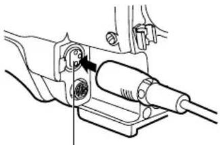
- Confirm that the POWER switch of the camera is "OFF".
- Insert the plug into the connection jack of the viewfinder.
Be sure to insert the plug all the way into the connection jack.
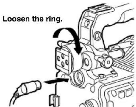
- Loosen the viewfinder left-right position anchoring ring.
- While pulling up the viewfinder stopper, attach the viewfinder by sliding it in the direction of the arrow.
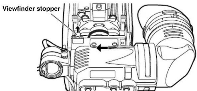
- Tighten the viewfinder left-right position anchoring ring.
For cameras compatible with the standard slide rail
Adjusting the viewfinder's left-right position
- Loosen the viewfinder left-right position anchoring ring.
- Slide the viewfinder to the left or right, and adjust it to a position that allows easy viewing.
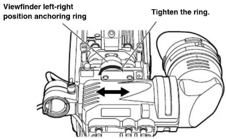
- Tighten the viewfinder left-right position anchoring ring.
Adjusting the viewfinder's front-back position
- Loosen the viewfinder front-back position anchoring ring.
- Slide the viewfinder to the front or back, and adjust it to a position that allows easy viewing.
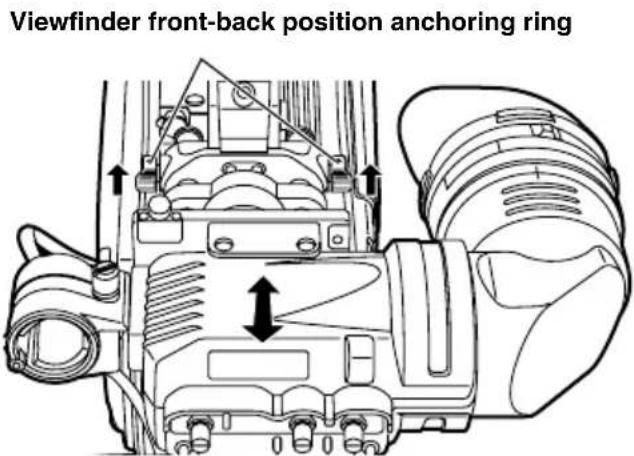
- Tighten the viewfinder front-back position anchoring ring.
For cameras compatible with the standard slide rail
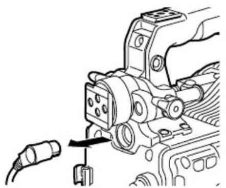
Detaching the Viewfinder
- Confirm that the POWER switch of the camera is "OFF".
- Loosen the viewfinder left-right position anchoring ring.
- While pulling up the viewfinder stopper, remove the viewfinder by sliding it in the direction of the arrow.
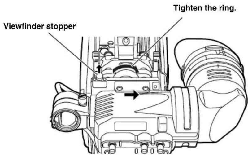
- Release the viewfinder cable and mic cable from the cable clamps, and disconnect the cables.
For cameras compatible with the mounting unit
The standard slide rail can be removed and replaced with the mounting unit (VYQ1818). To purchase the mounting unit, consult your dealer while bearing in mind that this unit is a repair part.
The following cameras support the mounting unit.
| Camera model numberViewfinder model number | |
| AJ-HVF21G | AJ-HDC20A AJ-HDC20AP |
| AJ-HVF27BG | AJ-HDC27F AJ-HDC27FP AJ-HDC27FE AJ-HDC27FMC |
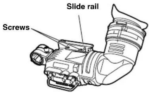
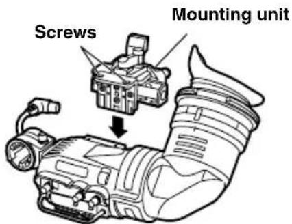
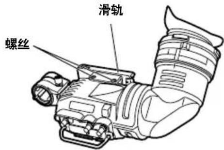
- Changing from the slide rail to the mounting unit
- Detach the two screws, then detach the standard slide rail.
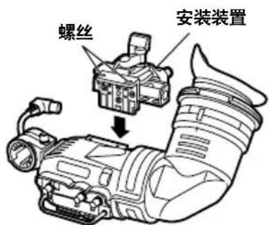
- Secure the mounting unit in place with the two screws.
For cameras compatible with the mounting unit
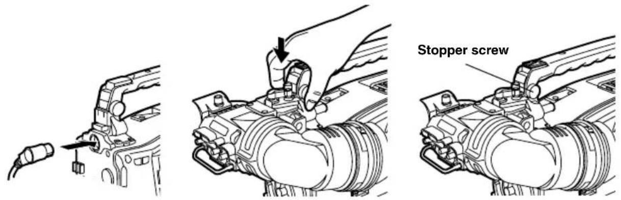
Mounting the Viewfinder
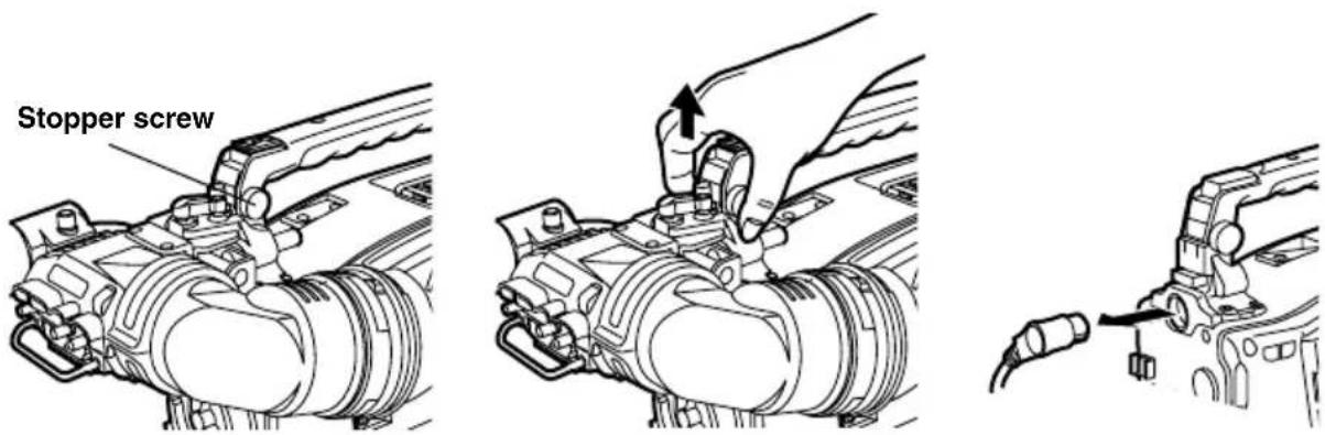
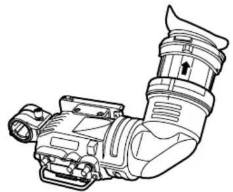
- Confirm that the POWER switch of the camera is "OFF".
- Insert the plug into the connection jack of the viewfinder.
Be sure to insert the plug all the way into the connection jack. - Push the viewfinder down into place.
- Tighten the stopper screw firmly.
Detaching the Viewfinder
- Confirm that the POWER switch of the camera is "OFF".
- Loosen the stopper screw and detach the viewfinder by pulling it straight up.
Use both hands to detach the viewfinder. The viewfinder may not detach smoothly with one hand, resulting in damage to the viewfinder. - Disconnect the connection jack from the viewfinder cable connector.
For cameras compatible with the mounting unit
Position Adjustment
- Lift up the viewfinder forward-backward/left-right position clamp lever to disengage the lock.
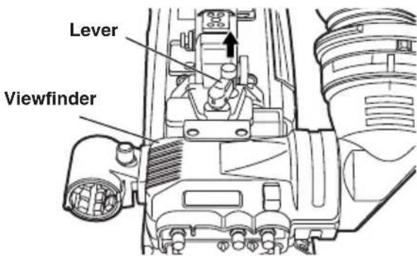
- Loosen the viewfinder forward-backward/left-right position clamp lever.
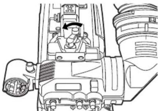
- Adjust the position of the viewfinder by moving it forward, backward, left or right.
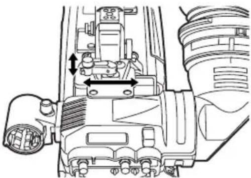
- Return the viewfinder forward-backward/left-right position clamp lever to the locked position.
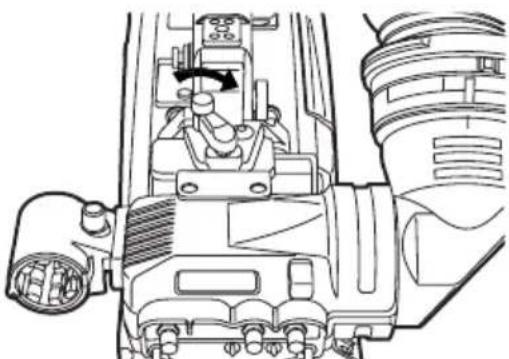
Diopter Adjustment
- Set the POWER switch of the camera to "ON". A picture will appear in the viewfinder.
- Turn the diopter adjustment ring to adjust the diopter so that the viewfinder picture can be clearly seen.
Screen Adjustment
Adjust the condition of the viewfinder screen.
Brightness:Adjust the BRIGHT control.
Contrast: Adjust the CONTRAST control.
Contour: Adjust the PEAKING control.
- Set the POWER switch of the camera to "ON".
- Set the OUTPUT switch of the camera to "BAR".
- Turn the viewfinder BRIGHT and CONTRAST controls to adjust the picture brightness and contrast.
Turning the PEAKING control makes the picture appear sharper.
A sharper picture facilitates focusing the lens.
Detaching the Eyepiece
If dust has adhered to the CRT screen or mirror, detach the eyepiece and remove it.
Do not wipe the mirror surface under any circumstances as it has been specially treated. Dust which has adhered to the mirror should be blown away with a blower, etc.
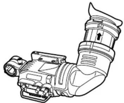
- Turn the lock ring as far as possible in the clockwise and counterclockwise directions to line up the alignment marks on the lock ring and viewfinder barrel.
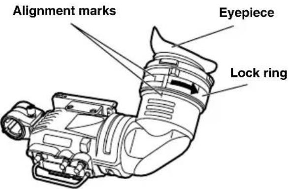
- Detach the eyepiece.
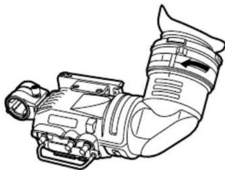
Remounting the Eyepiece
- Line up the alignment marks on the lock ring and the viewfinder barrel and slide the eyepiece back into place.
- Turn the lock ring clockwise as far as the
Mounting the Microphone
Follow the steps below to install the AJ-MC700P or the AJ-MC900G microphone kit (sold separately).
- Open the microphone holder.
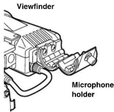
- Mount the microphone.
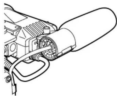
- Plug the microphone connector cable into the MIC IN jack.
MIC IN jack
Specifications
Power supply: DC 12 V (supplied by camera)
Power consumption: 3.8 W (AJ-HVF21G)
4.1 W (AJ-HVF27BG)

indicates safety information.
Picture tube:
2-inch high-resolution monochrome picture tube
Image system:
1080 lines, 50/60 fields selectable (AJ-HVF21G)
720 lines, 60 fields (AJ-HVF27BG)
External adjustment controls:
Controls (BRIGHT, CONTRAST, PEAKING)
Switches (TALLY HIGH/OFF/LOW, ZEBRA ON/OFF)
Allowable temperature range:
0ircC to 40ircC (32ircF to 104ircF)
Allowable humidity range:
85% or less (no condensation)
External dimensions (W× H× D)
240mm× 80mm× 206mm (9 1 / 2 inches × 3 3 / 16 inches × 8 1 / 8 inches)
Weight:
750 g (1.65 lb)
Information on Disposal for Users of Waste Electrical & Electronic Equipment (private households)

This symbol on the products and/or accompanying documents means that used electrical and electronic products should not be mixed with general household waste.
For proper treatment, recovery and recycling, please take these products to designated collection points, where they will be accepted on a free of charge basis. Alternatively, in some countries you may be able to return your products to your local retailer upon the purchase of an equivalent new product.
Disposing of this product correctly will help to save valuable resources and prevent any potential negative effects on human health and the environment which could otherwise arise from inappropriate waste handling. Please contact your local authority for further details of your nearest designated collection point.
Penalties may be applicable for incorrect disposal of this waste, in accordance with national legislation.
For business users in the European Union
If you wish to discard electrical and electronic equipment, please contact your dealer or supplier for further information.
Information on Disposal in other Countries outside the European Union
This symbol is only valid in the European Union.
If you wish to discard this product, please contact your local authorities or dealer and ask for the correct method of disposal.
WARNING:
- Retirer I'oeilleton.
| Modello videocameraNumero modello mirino | |
| AJ-HVF21G | AJ-HDX400AJ-HDX400P |
| AJ-HVF27BG | AJ-HDC27HAJ-HDC27HPAJ-HDC27HEAJ-HDC27HMC |
Interruttori (TALLY HIGH/OFF/LOW, ZEBRA ON/OFF)
| 摄像机型号寻像器型号 | |
| AJ-HVF21G | AJ-HDC20A AJ-HDC20AP |
| AJ-HVF27BG | AJ-HDC27F AJ-HDC27FP AJ-HDC27FE AJ-HDC27FMC |
- 将滑轨更换为安装装置
- 取下两颗螺丝,然后拆下标准滑轨。
- 将安装装置用两个螺丝固定。
有关兼容安装装置的摄像机
寻像器的安装
| ■確實に固定する! 外れと、落下いたします しぃけがの原因,Thま。 icanいようお願いいたします。 | ■本機を落とんだり、破損った 場合は、接続itraムを拔く! そのまま使用くださいます、 火災·感電を起こいたします その)+(ご)+(ご)+(ご)+(ご)+(ご)+(ご)+(ご)+(ご)+(ご)+(ご)+(ご)+(ご)+(ご)+(ご)+(ご)+(ご)+(ご)+(ご)+(ご)+(ご)+(ご)+(ご)+(ご)+(ご)+(ご)+(ご)+(ご)+(ご)+(ご)+(ご)+(ご)+(ご)+(ご)+(ご)+(ご)+(ご)+(ご)+(ご)+(ご)+(ご)+(ご)+(ご)+(ご)+(ご)+(ご)+(ご)+(ご)+(ご)+(ご)+(ご)+() |
| ■機器が濡�能た、水が入 らないようお願いいたします! 福災·感電の贈れ がお願いいたします。 雨天·降雪·海岸· 水辺deg使用は、特 icanご注意くださいます。 | ■本機の内部に異物や水 forallが入った場合は、接続itraムを拔く! そのまま使用くださいます、 と、火災·感電を起 て)+(ご)+(ご)+(ご)+(ご)+(ご)+(ご)+(ご)+(ご)+(ご)+(ご)+(ご)+(ご)+(ご)+(ご)+(ご)+(ご)+(ご)+(ご)+(ご)+(ご)+(ご)+(ご)+(ご)+(ご)+(ご)+(ご)+(ご)+(ご)+(ご)+(ご)+(ご)+(ご)+(ご)+(ご)+(ご)+(ご)+(ご)+(ご)+(ご)+(ご)+(ご)+(ご)+(ご)+(ご)+(ご)+(ご)+(ご)+(ご)+(ご)+() |
| ■接続itraムは、根元まで確 宜に差しります! 感電の原則に推薦= ican。 ican。 ican。 ican。 ican. ican. ican. ican. ican. ican. ican. ican. ican. ican. ican. ican. ican. ican. ican. ican. ican. ican. ican. ican. ican. ican. ican. ican. ican. ican ican. ican. ican. ican. ican. ican. ican. ican. ican. ican. ican. ican. ican. ican. ican. ican. ican. ican. ican. ican. ican. ican. ican. ican. ican; ican. ican. ican. ican. ican. ican. ican. ican. ican. ican. ican. ican. ican. ican. ican. ican. ican. ican. ican. ican. ican. ican. ican. ican. ican, ican. ican. ican. ican. ican. ican. ican. ican. ican. ican. ican. ican. ican. ican. ican. ican. ican. ican. ican. ican. ican. ican. ican. ican. ican? ican. ican. ican. ican. ican. ican. ican. ican. ican. ican. ican. ican. ican. ican. ican. ican. ican. ican. ican. ican. ican. ican. ican. ican. ican。 ican. ican. ican. ican. ican. ican. ican. ican. ican. ican. ican. ican. ican. ican. ican. ican. ican. ican. ican. ican. ican. ican. ican. ican ican ican. ican. ican. ican. ican. ican. ican. ican. ican. ican. ican. ican. ican. ican. ican. ican. ican. ican. ican. ican. ican. ican. ican. ican ican; ican. ican. ican. ican. ican. ican. ican. ican. ican. ican. ican. ican. ican. ican. ican. ican. ican. ican. ican. ican. ican. ican. ican. ican ican。 ican. ican. ican. ican. ican. ican. ican. ican. ican. ican. ican. ican. ican. ican. ican. ican. ican. ican. ican. ican. ican. ican. ican. ican; ican ican. ican. ican. ican. ican. ican. ican. ican. ican. ican. ican. ican. ican. ican. ican. ican. ican. ican. ican. ican. ican. ican. ican. ican; ican; ican; ican; ican; ican; ican; ican; ican; ican; ican; ican; ican; ican; ican; ican; ican; ican; ican; ican; ican; ican; ican; ican; ican; ican ican; ican; ican; ican; ican; ican; ican; ican; ican; ican; ican; ican; ican; ican; ican; ican; ican; ican; ican; ican; ican; ican; ican; ican; ican. ican; ican; ican; ican; ican; ican; ican; ican; ican; ican; ican; ican; ican; ican; ican; ican; ican; ican; ican; ican; ican; ican; ican; ican ican ican ican ican ican ican ican ican ican ican ican ican ican ican ican ican ican ican ican ican ican ican ican ican ican. ican ican ican ican ican ican ican ican ican ican ican ican ican ican ican ican ican ican ican ican ican ican ican ican ican; ican ican ican ican ican ican ican ican ican ican ican ican ican ican ican ican ican ican ican ican ican ican ican ican. ican. ican ican ican ican ican ican ican ican ican ican ican ican ican ican ican ican ican ican ican ican ican ican ican ican. ican; ican ican ican ican ican ican ican ican ican ican ican ican ican ican ican ican ican ican ican ican ican ican ican ican; ican; ican ican ican ican ican ican ican ican ican ican ican ican ican ican ican ican ican ican ican ican ican ican ican. ican ican; ican ican ican ican ican ican ican ican ican ican ican ican ican ican ican ican ican ican ican ican ican ican ican. ican; ican; ican ican ican ican ican ican ican ican ican ican ican ican ican ican ican ican ican ican ican ican ican ican ican; ican ican; ican ican ican ican ican ican ican ican ican ican ican ican ican ican ican ican ican ican ican ican ican ican ican; ican; ican; ican ican ican ican ican ican ican ican ican ican ican ican ican ican ican ican ican ican ican ican ican ican. ican ican ican. ican ican ican ican ican ican ican ican ican ican ican ican ican ican ican ican ican ican ican ican ican ican. ican ican ican; ican ican ican ican ican ican ican ican ican ican ican ican ican ican ican ican ican ican ican ican ican ican. ican ican. ican ican ican ican ican ican ican ican ican ican ican ican ican ican ican ican ican ican ican ican ican ican ican. ican ican. ican. ican ican ican ican ican ican ican ican ican ican ican ican ican ican ican ican ican ican ican ican ican ican. ican ican. ican; ican ican ican ican ican ican ican ican ican ican ican ican ican ican ican ican ican ican ican ican ican ican. ican ican; ican; ican ican ican ican ican ican ican ican ican ican ican ican ican ican ican ican ican ican ican ican ican ican. ican; ican ican; ican ican ican ican ican ican ican ican ican ican ican ican ican ican ican ican ican ican ican ican ican ican. ican; ican; ican; ican ican ican ican ican ican ican ican ican ican ican ican ican ican ican ican ican ican ican ican ican ican; ican; ican ican; ican ican ican ican ican ican ican ican ican ican ican ican ican ican ican ican ican ican ican ican ican ican; ican; ican; ican; ican ican ican ican ican ican ican ican ican ican ican ican ican ican ican ican ican ican ican ican ican; ican; ican; ican ican; ican ican ican ican ican ican ican ican ican ican ican ican ican ican ican ican ican ican ican ican ican; ican; ican; ican; ican; ican; ican; ican; ican; ican; ican; ican; ican; ican; ican; ican; ican; ican; ican; ican; ican; ican; ican; ican ican; |

警告
水場で使用くださ!

火災·感電の原因と訪問。
水場使用禁止
■不安定場所に置,No!

禁止
Government Marketing Department:
One Panasonic Way 2E-10, Secaucus, NJ 07094 (201) 348-7587
Broadcast PARTS INFORMATION & ORDERING:
9:00 a.m. - 5:00 p.m. (EST) (800) 334-4881/24 Hr. Fax (800) 334-4880
Emergency after hour parts orders (800) 334-4881
TECHNICAL SUPPORT:
Emergency 24 Hour Service (800) 222-0741
Panasonic Canada Inc.
5770 Ambler Drive, Mississauga, Ontario L4W 2T3 (905) 624-5010
Panasonic de Mexico S.A. de C.V.
Av angel Urraza Num. 1209 Col. de Valle 03100 Mexico, D.F. (52) 1951 2127
Panasonic Puerto Rico Inc.
San Gabriel Industrial Park, 65th Infantry Ave., Km. 9.5, Carolina, Puerto Rico 00630 (787) 750-4300
Panasonic Broadcast Europe
Panasonic Marketing Europe GmbH
Hagenauer Str. 43, 65203 Wiesbaden-Biebrich Deutschland Tel: 49-611-235-481
松下电器产业株式会社
Web Site: http://panasonic.net
- Operating precaution
- Caution:
- Precautions for Use (For USA)
- FCC Note:
- Warning:
- Notice (U.S.A.only):
- Notice (For Canada)
- Contents
- Features
- Parts and Their Functions
- ZEBRA (Zebra Pattern) Switch
- TALLY Switch
- PEAKING Knob
- CONTRAST Knob
- BRIGHT (Brightness) Knob
- Front Tally Lamp
- Viewfinder stopper
- Eyepiece
- Back Tally Lamp
- Diopter Adjustment Ring
- Connection Plug
- Lock Ring
- Microphone Holder
- Slide rail
- Internal LEDs
- For cameras compatible with the standard slide rail
- Mounting the Viewfinder
- Adjusting the viewfinder's left-right position
- Adjusting the viewfinder's front-back position
- Detaching the Viewfinder
- For cameras compatible with the mounting unit
- - Changing from the slide rail to the mounting unit
- Position Adjustment
- Diopter Adjustment
- Screen Adjustment
- Detaching the Eyepiece
- Remounting the Eyepiece
- Mounting the Microphone
- Specifications
- Picture tube:
- Image system:
- External adjustment controls:
- Allowable temperature range:
- Allowable humidity range:
- External dimensions (W× H× D)
- Weight:
- Information on Disposal for Users of Waste Electrical & Electronic Equipment (private households)
- For business users in the European Union
- Information on Disposal in other Countries outside the European Union
- - 将滑轨更换为安装装置
- 有关兼容安装装置的摄像机
- 寻像器的安装
- 警告
- 水場で使用くださ!
- ■不安定場所に置,No!
- 松下电器产业株式会社
Brand : PANASONIC
Model : AJHVF21G
Category : Camcorder