
N 8 - Electric converter DOMETIC - Free user manual and instructions
Find the device manual for free N 8 DOMETIC in PDF.

| Brand | Dometic |
| Model | N 8 |
| Category | AC/DC Electrical Converter |
| Input Power | 230 V AC / 12 V DC (AC priority) |
| Maximum Power | 400 W (depending on version) |
| Output Voltage | 12.7 V DC |
| Max Output Current | 31.5 A (depending on version) |
| Ambient Temperature Range | Up to 50 °C (vertical mount) or 40 °C (horizontal) |
| Overload Protection | Yes (thermal and electronic) |
| Short Circuit Protection | Yes |
| Overvoltage Protection | Yes (circuit breaker at ~270 V AC) |
| LED Indicators | Green (mains present), red (overvoltage or defective fuse) |
| Output Fuses | Type ATO, replace with same type |
| Recommended Mounting | Vertical, with at least 200 mm clearance above |
| Installation | By the vehicle manufacturer, do not modify |
| Intended Use | Power supply for 12 V devices in continuous operation |
| Maintenance | Ensure good ventilation, do not cover |
| Safety | Do not use in explosive areas |
| User Manual | Included, 40 pages (FR, DE, EN, IT, NL) |
Frequently Asked Questions - N 8 DOMETIC
User questions about N 8 DOMETIC
0 question about this device. Answer the ones you know or ask your own.
Ask a new question about this device
Download the instructions for your Electric converter in PDF format for free! Find your manual N 8 - DOMETIC and take your electronic device back in hand. On this page are published all the documents necessary for the use of your device. N 8 by DOMETIC.
USER MANUAL N 8 DOMETIC
natural_image
Front view of a portable air conditioner unit with ventilation grilles and a small electronic component (no text or symbols visible)DE Dometic Schaltnetzteile 230V/12V für Freizeitfahrzeuge
EN Dometic converters 230V/12V for recreational vehicles
FR Dometic convertisseurs 230V/12V pour véhicules de loisirs
IT Dometic convertitori 230V / 12V per veicoli ricreazionali
NL Dometic omvormer 230V / 12V voor recreatievoertuigen
Deutsch 3
English 9
Français 15
Italiano 21
Nederlands 27
Dometic
Dometic Light Systems GmbH
Dillenburger Straße 59
D-35685 Dillenburg
www.dometic.com
Inhaltsverzeichnis
1.0 Allgemeines 4
natural_image
Diagram of a cable connector with two connectors, one labeled with number 1 (no text or symbols beyond label)Abb. 1
3.2.4 Sicherungen
Abb. 2
1.1 Description of product and application 10
1.2 Guide to these operating instructions 10
1.3 Copyright protection 10
1.4 Explanation of symbols used in this manual 10
1.5 Warranty 11
1.6 Limitation of liability 11
2.0 Safety instructions .... 11
2.1 Application according to regulations 11
2.2 User's responsibility 11
3.0 Operation of the AC/DC converter 12
3.1 Switching on 12
3.2 Safety devices 12
3.2.1 Overtemperature protection 12
3.2.2 Overload protection and short-circuit protection 12
3.2.3 Surge voltage protection 13
3.2.4 Fuses 13
3.3 Measures in case of malfunctions 13
4.0 Installation 14
4.1 Installation 14
4.1.1 Vertical Installation 14
4.1.2 Horizontal Installation 14
5.0 Technical Data 33
5.1 Type I 33
5.2 Type IIa 34
5.3 Type IIb 35
6.0 Table 36
1.0 General
1.1 Description of product and application
Dometic AC/DC converters are used for the power supply of 12 V appliances in continuous operation. The input voltage thereby comes either from the 230 V AC mains power supply (Priority 230VAC).
1.2 Guide to these operating instructions
Read the operating instructions carefully before you use the AC/DC converter.
These instructions provide you with the necessary guidance for the proper use of your AC/DC-converter. Observe in particular the safety instructions. Compliance with the instructions and handling recommendations is important for dealing with the AC/DC-converter safely and for protecting you from injury and the appliance from damage. You must understand what you have read before you carry out a task.
Keep this operating manual carefully and ready to hand so that it can be used at any time.
1.3 Copyright protection
The information, texts and illustrations in these instructions are copyright protected and are subject to industrial property rights. No part of these instructions may be reproduced, copied or used in any other way without written authorisation by Dometic Light Systems GmbH, Dillenburg.
1.4 Explanation of symbols used in this manual
Warning notices
Warning notices are identified by symbols. A supplementary text gives you an explanation of the degree of danger.
Observe these warning notices rigorously. You will thus protect yourself and other people from injury, and the appliance from damage.

WARNING!
WARNING indicates a potentially hazardous situation which could result in death or serious injury if the given instructions are not adhered to.

CAUTION!
CAUTION indicates a potentially hazardous situation which can result in minor or moderate injury if the given instructions are not adhered to
CAUTION!
CAUTION (used without the safety alert symbol) indicates a potentially hazardous situation which can result in damage to the appliance if the given instructions are not adhered to.
Information

INFORMATION gives you supplementary and useful guidance for dealing with your refrigerator.
Environmental tips

ENVIRONMENTAL TIPS give you useful guidance for saving energy and disposal of the appliance.
1.5 Warranty
Warranty arrangements are in accordance with EC Directive 44/1999/CE and the normal conditions applicable for the country concerned. Any damage due to improper use is not covered by the warranty.
1.6 Limitation of liability
All information and guidance in these operating instructions were prepared after taking into consideration the applicable standards and regulations as well as the current state of the art. Dometic reserves the right to make changes at any time which are deemed to be in the interest of improving the product and safety.
Dometic will assume no liability for damage in the case of :
■non-observation of the operating instructions
■application not in accordance with the regulations or provisions
■use of non-original spare parts
■modifications and interferences to the appliance
■effect of environmental influences, such as
- temperature fluctuations
- humidity
2.0 Safety instructions
2.1 Application according to regulations
Dometic AC/DC converters are used for the power supply of 12 V appliances in continuous operation.
2.2 User's responsibility
Anyone operating the Dometic AC/DC converters must be familiar with the safe handling and understand the instructions in this operating manual.
Non-observance of the following safety instructions can result in serious damage to the Dometic AC/DC converter and adjacent areas.

WARNING!
Do not make any changes to or additional installations at the Dometic AC/DC converter or to the installation performed by the vehicle manufacturer.

WARNING!
The Dometic AC/DC converter must not be used in potentially explosive gas or dust areas.
CAUTION!
The Dometic AC/DC converter must not be covered or exposed to environmental conditions which adversely affect the ventilation of the unit.
3.0 Operation of the AC/DC converter
3.1 Switching on
■ Devices of the type 1 (see Fig. 4page 33) can be switched on and off using the On/Off switch. 230 V AC input voltage is available when the LED under the ON/OFF switch is lit green. If the green LED does not light, there is no 230 V AC input voltage present at the unit or the device has switched off due to overheating (see point 3.2.1).
■ Devices of the types 2 a + b switch on as soon as 230 V voltage is available at the connection.
The consumers can be supplied with power independently of the 230 V operation using a 12 V DC energy source (e.g. battery) if this is connected to the converter. The internal priority circuit disconnects the 12 V DC energy source automatically as soon as 230 V AC is present. The AC/DC converter is not a charger.
Note that high currents flow over the units due to the device-specific high power although they only produce a voltage of 12 V. Strictly ensure that the power of the consumers connected to the respective output complies with the requirements under point 3.2.4. Changes to the installation must only be performed by authorised specialists in agreement with the vehicle manufacturer.
3.2 Safety devices

Dometic AC/DC converters have various safety functions for your safety.
3.2.1 Overtemperature protection
■The thermal overload cut-out trips in the case of the unit overheating. To reactivate the unit, first switch it OFF. Wait for at least 60 seconds before restarting the system.
230VAC supply
As soon as the circuit breaker (in the fuse box) is in the ON position and the vehicle is connected to a 230V AC power supply, the AC/DC converter is ready for operation.
12VDC supply
If no 230V AC supply is available, a 12V DC power source (e.g. battery) can be connected to the AC/DC converter; the consumers will then be supplied from this source.
If the thermal overload cut-out trips again and switches off the appliance, the cause may be insufficient ventilation. If this is the case, provide better ventilation and restart the unit.
If the thermal overload cut-out still trips afterwards, please contact an authorised Dometic service partner.
3.2.2 Overload protection and short-circuit protection
The overload cut-out trips under the following conditions:
In the case of moderate overload which results in high internal temperatures with increasing operation duration and then trips the overload cut-out mentioned above. This reduces the output voltage and the under voltage cut-out trips.
The unit is equipped with internal short-circuit monitoring. As soon as a preset value is reached, this cut-out trips and switches off the unit without blowing fuses. Caution is required in this case.
3.2.3 Surge voltage protection
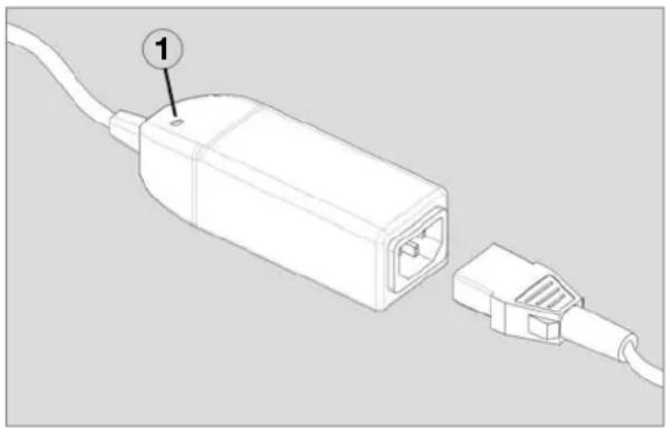
The Dometic surge voltage protection (OVP unit, Fig. 1) is installed upstream of the transformer. It disconnects the supply line if the input voltage exceeds approx. 270 V\~. Connected equipment is protected.
A red LED (1) indicates that a surge voltage was present.
The Dometic surge voltage protection resets itself automatically when the voltage has reached a normal level again. The LED is still lit 20 to 30 minutes after the voltage has reached a safe level again.
natural_image
Diagram of a cable connector with two connectors, one labeled with number 1 (no text or symbols on the diagram itself)Fig. 1
3.2.4 Fuses
The power units can be fitted with different fuses.
It must be strictly ensured during the installation that the power taken off at the individual fuses is maximum 75% of the rated value of the respective fuse. Higher outputs can result in overheating and damage due to the higher current.
A defective fuse usually means a short-circuit or an overload of the 12 V output. This is indicated by a red LED lighting next to the fuse (see Fig. 2) if a consumer is connected.
A defective fuse in the fuse holder is also only indicated when a consumer is connected. In the case of a defective fuse, attempt to localise the cause in the 12 V power circuit and rectify if possible.
Switch off the AC/DC converter or disconnect the device from the 230 V AC power supply
before replacing the fuse. Only replace a defective fuse with a new fuse of the ATO type LITTLEFUSE.
Switch on the unit again (see Fig. 4). If the fuse trips again, contact a service partner for Dometic AC/DC converters.
3.3 Measures in case of mal- functions
1 No current supply to 230 V and 12 V mains operation; the green LED does not light up.
a. Check whether power has been disconnected; restore connection, if necessary. Check whether the automatic cut-out has been activated.
2 No current supply to the 12 V mains operation.
a. Check the 12 volt plug-in fuses: faulty fuses are indicated by the red LED.
If necessary, replace the fuses by new fuses of the same type and the same current intensity.
b. Check whether the unit has switched off because of overheating: the green LED does not light up. Switch off the unit and wait at least 2 minutes before restarting it.
3 No current supply to the 12 V outputs by battery operation.
a. Check the 12 volt plug-in fuses: faulty fuses are indicated by the red LED. If necessary, replace the fuses by new fuses of the same type and the same current intensity.
b. Check the battery and its connection to the converter.
4.0 Installation
4.1 Installation

WARNING!
Dometic AC/DC converters are permanently installed and connected by the vehicle manufacturer. It is not permitted to connect cables to the unit or remove them from it or to modify the installation in any other way.
■ Install the AC/DC converter at a place which is well ventilated and protected against moisture. In order to achieve optimum heat removal, the device must be mounted vertically (see Fig. 2).
■Comply with the stated clearances for the installation. There must be no easily inflammable materials such as textiles, paper etc. located in this area.
■ Ensure that the air circulation is neither obstructed by covers or other disruptive influences.
The AC/DC converter can only be operated with sinusoidal mains voltage (230 V AC). If a generator provides this voltage, surge voltage protection should be installed upstream of the power unit.
4.1.1 Vertical Installation
The optimum installation of the AC/DC converter is in the vertical position (Fig. 2). The maximum permitted ambient temperature is 50 °C.
A: Wall
B: Side wall
C: Ceiling
D: Floor / platform
E: maintain a distance of at least 200 mm above the power unit
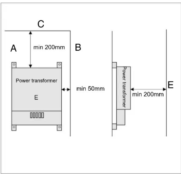
Fig. 2
4.1.2 Horizontal Installation
The second possibility for installing the AC/DC converter is the horizontal installation on the floor or on a platform.
The maximum permitted ambient temperature is only 40 °C.
(40-50°C ok with max 75% load)
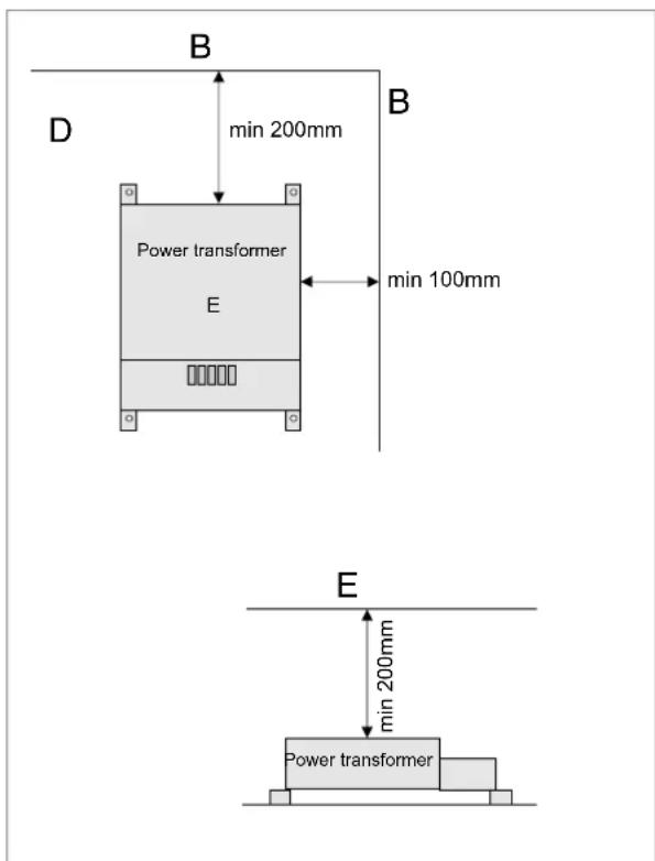
Fig. 3
Table de matière
natural_image
Diagram of a cable connector with two connectors, one labeled with number 1 (no text or symbols on the diagram itself)Fig. 1
3.2.4 Fusibles
Fig. 2
4.1.2 Montage horizontal
natural_image
Diagram of a cable connector with a labeled pin (1) and a separate plug inserted into the cable (no text or symbols present)Fig. 1
3.2.4 Fusibili
Fig. 2
natural_image
Diagram of a cable connector with a labeled pin (1) and a separate connector (no text or symbols present)Afb. 1
3.2.4 Zekeringen
Afb. 2
Type II transformers have no additional main switch and no fan.
natural_image
Technical line drawing of a mechanical or electrical enclosure with ventilation grilles and internal components (no text or symbols)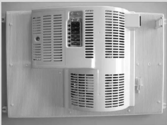
natural_image
Exterior view of a white industrial ventilation unit with ventilation grilles and control panel (no visible text or symbols)Fig. 6
6.0 Tabelle / Table / Tabella / Tabel
DE / Tabelle
| Article number | Wattage | Voltage | Amper-age | Specifications |
| 70270.9701 | 400 W | 12.7 V | 32 A | |
| 70270.9702 | 400 W | 12.7 V | 32 A | 12V outputs with "Stocko" contacts |
| 70270.9703 | 400 W | 12.7 V | 32 A | Electric circuit +P1 not connected at 12V |
| 70270.9704 | 450 W | 12.7 V | 35 A | 12V outputs with "Stocko" contactsStromkreis +P2 bei 12V nicht durchgeschaltet |
| 70270.9706 | 240 W | 12.7 V | 19 A | |
| 70270.9707 | 240 W | 12.7 V | 31.5 A | "Mate-N-Lock" plug & drive system |
| 70270.9708 | 400 W | 12.7 V | 31.5 A | Electric circuit +P4 and +P5 not connected at 12V |
| 70270.9712 | 400 W | 12.7 V | 31.5 A | 12V outputs with "Stocko" contacts |
| 70270.9713 | 450 W | 12.7 V | 35 A | 12V outputs with "Stocko" contacts |
| 70270.9714 | 600 W | 12.7 V | 47 A | |
| 70270.9716 | 400 W | 12.7 V | 31.5 A | |
| 70270.9717 | 450 W | 12.7 V | 35 A | Without output fuses |
| 70270.9718 | 400 W | 12.7 V | 31.5 A | Without output fuses |
| 70270.9719 | 600 W | 12.7 V | 47 A | Without output fuses |
| 70270.9727 | 450 W | 12.7 V | 35 A | With output fuses |
| 70270.9728 | 400 W | 12.7 V | 31.5 A | With output fuses |
| 70270.9729 | 600 W | 12.7 V | 47 A | With output fuses |
FR / Table
- Dometic
- Inhaltsverzeichnis
- Allgemeines 4
- Sicherungen
- Safety instructions .... 11
- Operation of the AC/DC converter 12
- Installation 14
- Technical Data 33
- Table 36
- General
- Description of product and application
- Guide to these operating instructions
- Copyright protection
- Explanation of symbols used in this manual
- WARNING!
- CAUTION!
- Warranty
- Limitation of liability
- Safety instructions
- Application according to regulations
- User's responsibility
- Operation of the AC/DC converter
- Switching on
- Safety devices
- Overtemperature protection
- Overload protection and short-circuit protection
- Surge voltage protection
- Fuses
- Measures in case of mal- functions
- No current supply to 230 V and 12 V mains operation; the green LED does not light up.
- No current supply to the 12 V mains operation.
- No current supply to the 12 V outputs by battery operation.
- Installation
- Installation
- Vertical Installation
- Horizontal Installation
- Table de matière
- Fusibles
- Montage horizontal
- Fusibili
- Zekeringen
- Tabelle / Table / Tabella / Tabel
Brand : DOMETIC
Model : N 8
Category : Electric converter