
Iris - Metric counter Lofrans - Free user manual and instructions
Find the device manual for free Iris Lofrans in PDF.


| Product type | Metric counter for windlass |
| Brand | Lofrans |
| Model | Iris |
| Dimensions (L x W x H) | 100 x 100 x 32 mm (without protective cover) |
| Weight | 160 g |
| Supply voltage | 10 to 30 V DC |
| Current consumption | Min 5 mA – Max 40 mA |
| Protection degree (front part) | IP65 |
| Operating temperature | 0°C to +70°C (32°F to 158°F) |
| Display | Graphic monitor 128 x 64 pixels |
| Maximum measurable length | 999 meters or 999 feet |
| Measurement units | Meters/centimeters or feet/inches |
| Main functions | Chain length display, ascent/descent speed, ascent alarm, automatic descent, operating hours counter |
| Included material | Metric counter, gasket and closing cover, 10-pole male connector with crimp contacts, magnetic sensor, support kit (support for vertical axis windlass, support base, 2 fixing screws, O-ring), magnet, sensor support for horizontal axis windlass, instruction manual |
| Sensor type | Magnetic (automatic detection Standard or Project) |
| Available settings | Screen contrast and brightness, backlight time (default 30 s), key beep on/off, language selection (Italian, English, French, German, Spanish) |
| Alarms and safety | Adjustable ascent alarm (1.0 to 5.0 m/feet), programmable automatic descent (5 to 40 m/feet), automatic stop if sensor signal absent >5 s, 4 A fuse protection on cable + battery |
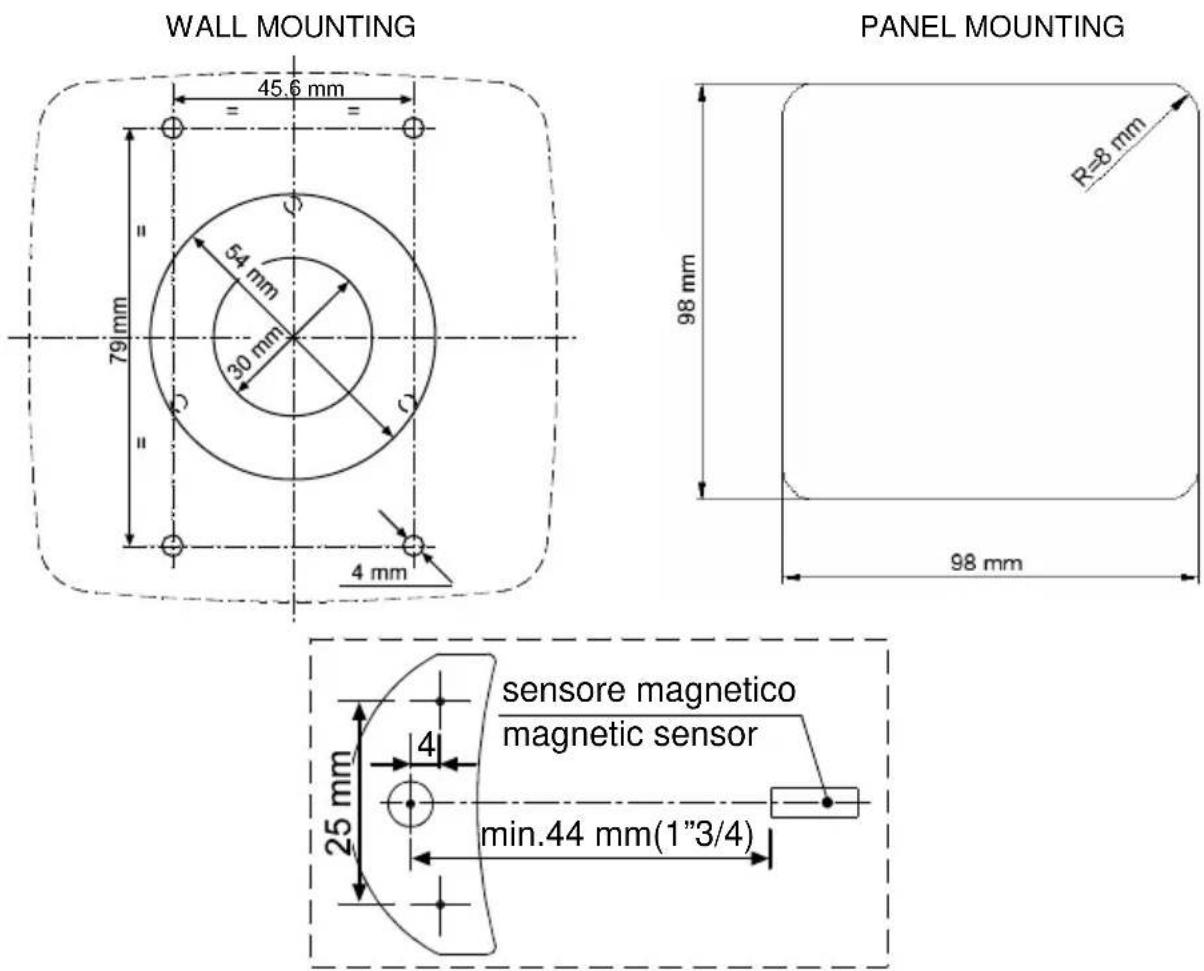
| Installation | Dashboard mounting (cutout 30 mm diameter + 4 holes of 4 mm) or surface mounting (cutout 54 mm). Requires drilling for sensor cable passage (4 mm). Minimum distance from compass: 30 cm, from radio devices: 50 cm, from transmitting stations: 2 m, from radar beam: 2 m |
| Electrical connection | Rear 10-pole connector: PIN 1 (+ battery), PIN 3 (- battery), PIN 6 (UP command), PIN 7 (DOWN command), PIN 10 (magnetic sensor). 4 A fuse on + cable. Do not use motor group current |
| Warranty | 2 years against manufacturing defects, excluding transport, improper installation, unauthorized repairs |
Frequently Asked Questions - Iris Lofrans
User questions about Iris Lofrans
0 question about this device. Answer the ones you know or ask your own.
Ask a new question about this device
Download the instructions for your Metric counter in PDF format for free! Find your manual Iris - Lofrans and take your electronic device back in hand. On this page are published all the documents necessary for the use of your device. Iris by Lofrans.
USER MANUAL Iris Lofrans
natural_image
Line drawing of a mechanical pulley or lever mechanism with chain and circular components (no text or symbols)Fig. 1A
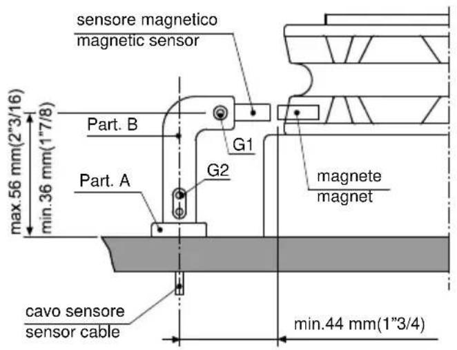
Fig. 1B

Fig. 2C
Descrizione
MONTAGGIO A PARETE - WALL MOUNTING
natural_image
Exploded view diagram of a device showing internal components and assembly (no text or labels)MONTAGGIO A PANNELLO - PANEL MOUNTING
natural_image
Exploded view diagram of a device showing internal components and assembly (no text or labels)
natural_image
Technical line drawing of a mechanical component with mounting holes and a central circular feature (no text or symbols)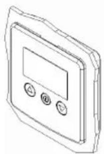
natural_image
Line drawing of a rectangular electronic device with three buttons and a display screen (no text or symbols)| CONNETTORE POSTERIORE A 10 POLI | |
| PIN SEGNALE | |
| 1 + Batteria | |
| 2 | |
| 3 - Batteria | |
| 4 | |
| 5 | |
| 6 Comando UP | |
| 7 Comando DOWN | |
| 8 | |
| 9 | |
| 10 Sensore magnetico | |
natural_image
Simple line drawing of a control panel with three buttons (triangle, circle, inverted triangle) and a blank display area (no text or symbols)The Iris chain counter displays the length of chain let out or down, expressed in metres or feet and the speed of the same.
Technical data
| Power supply f | rom 10 to 30 V DC |
| Current intake min. 5 mA – max 40 mA | |
| Protection rating of front cover IP65* | |
| Operative temperature 0 / +70 °C (32 / 158 °F) | |
| Graphic display 128 x 64 pixels | |
| Max. chain length 999 metres – 999 feet | |
| Size (mm) 100 x 100 x 32** | |
| Weight (g) 160 |
* excluding cable connection zone - ** without protective cover

Warning
CONNECT ONLY TO A DC POWER SUPPLY.
General notes
The Iris chain counter must be used solely for the purposes described herein, i.e. to operate and display the number of metres/feet of chain let out by an anchor windlass. Any other use is to be considered improper.
Any tampering with the instrument will result in immediate voiding of the warranty.
Components
The package contains:
• chain counter, seal and closure cover;
• 10-pole male connector with crimp-type10 male contacts;
• magnetic sensor;
- support kit (support for the vertical shaft anchor windlass sensor, supporting base, 2 fastening screws, O-ring);
- magnet;
• horizontal shaft anchor windlass sensor support;
- instructions for use.
Installation
On a few models of anchor windlass the sensor and the magnet are already installed (chain counter setting). Therefore, the operations described below are not necessary.
Installing the magnet on the anchor windlass
- A hole having a diameter of 6.5 mm (\~1/4") and depth of 8 mm (5/16") must be drilled on a tooth of the gipsy, in a place outside the chain's path.
- In the case of vertical shaft anchor windlasses (see Fig. 1B), drill the hole in the lower circumference of the gipsy.
• In the case of horizontal shaft anchor windlasses (see Fig. 2B), drill the hole in the outer circumference of the gipsy.
• Also make sure that the protruding part of the magnet will not collide with the base or sensor during rotation of the gipsy. - Insert the metal part of the magnet in the hole, allowing the protected part to protrude by about 2 mm. Fix it in place using an adhesive for metals (two-component epoxy glue) or silicone. The glue used must be able to withstand a marine environment.
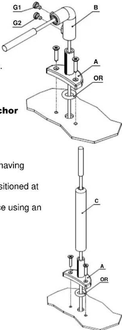
Installing the magnetic sensor for vertical shaft anchor windlasses
(see Fig. 1A - 1B)
- Drill a 4 mm (\~3/16") hole in the cover through which to thread the sensor cable.
- Fasten Part A of the support with the two screws provided, after having positioned the O-ring in the lower part of the support.
- Fit Part B with the magnetic sensor on support A and adjust its height until it is aligned with the magnet fastened on the gipsy.
- Bring the sensor to a distance of about 3 mm (\~1/8") from the magnet and secure it in place by tightening screw G1. Then tighten screw G2.
Installing the magnetic sensor for horizontal shaft anchor windlasses
(see Fig. 2A - 2B - 2C)
- Drill a 4 mm (\~3/16") hole in the cover through which to thread the sensor cable.
- Fasten Part A of the support with the two screws provided, after having positioned the O-ring in the lower part of the support.
- Cut Part C to measure using a hacksaw. The sensor must be positioned at a distance of about 3 mm (\~1/8") from the magnet.
- Fit Part C with the magnetic sensor on support A and fix it in place using an adhesive for plastic (two-component epoxy glue) or silicone.
• Using the same glue, attach the sensor to Part C.
Installing the chain counter
(see connection diagram)

Warning
ALWAYS DISCONNECT THE BATTERY PRIOR TO INSTALLATION.
- The chain counter must be positioned so that the display will be easy to read. It should not be exposed to direct sunlight.
- The rear part of the instrument must be protected from contact with water or moisture.
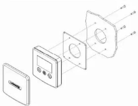
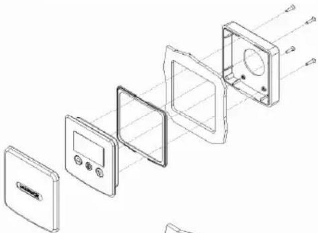
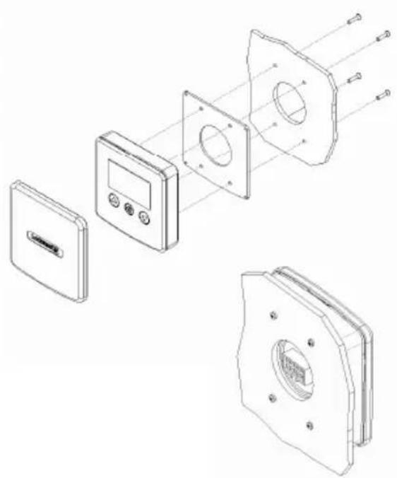
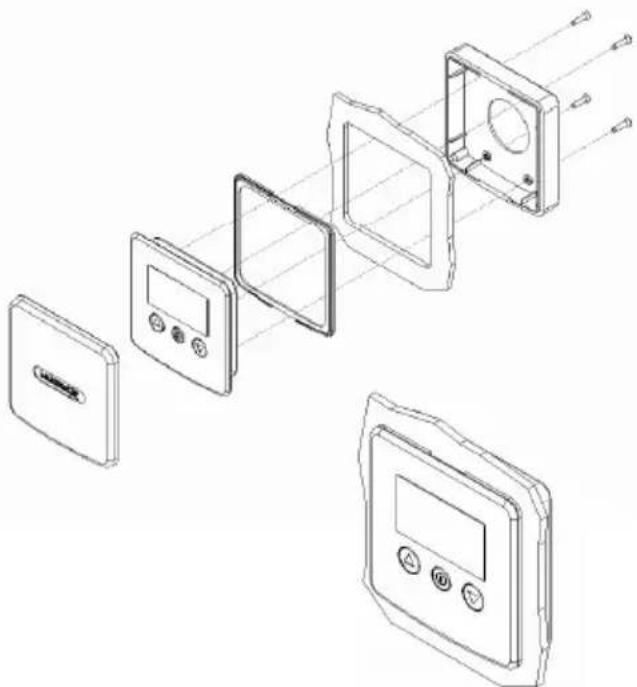
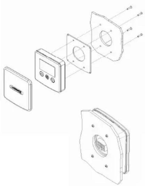
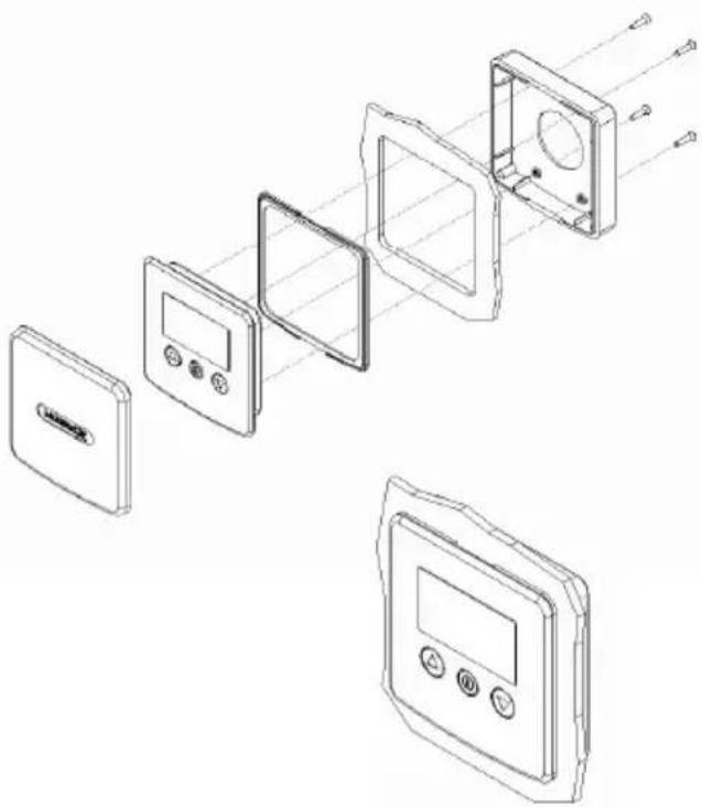
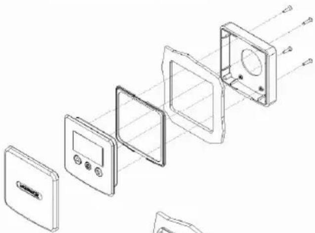
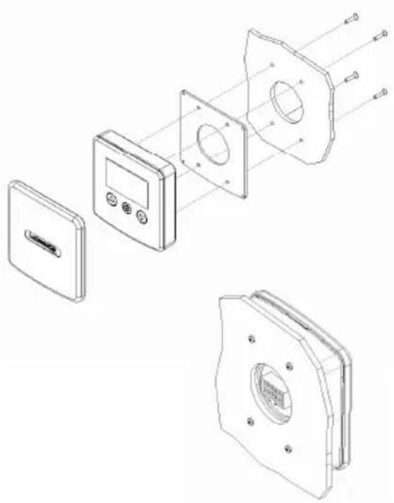
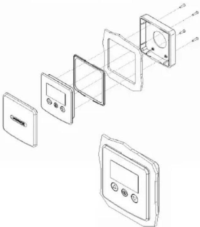
- The instrument may be fastened to dashboards of any thickness. The screws used for clamping must be of the self-threaded kind and with a diameter of 3.5 mm (\~9/64") and a maximum length of 10 mm plus the thickness of the dashboard.
- In the part to the rear of the dashboard there must be minimum clearance of 35 mm (1" 3/8) and there must also be adequate access to perform installation and maintenance work.
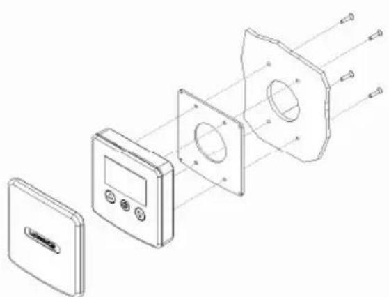
- On the dashboard make a hole with a diameter of 30 mm (\~1" 3/16), as indicated, and 4 holes with diameters of 4 mm (\~5/32") for the chain counter clamping screws. Use cutting nippers to cut the three pins on the back of the instrument, position the chain counter and fasten it to the dashboard by tightening the four screws. If the dashboard already has a hole with a 54 mm (2"1/8) diameter, it is not necessary to cut the pins on the back.
- The seal must be positioned between the chain counter and the dashboard.
MONTAGGIO A PARETE - WALL MOUNTING
natural_image
Exploded view diagram of a device showing internal components and assembly (no text or labels)MONTAGGIO A PANNELLO - PANEL MOUNTING
natural_image
Exploded view diagram of a smart home control panel showing internal components and wiring (no text or labels)For instructions on making electrical connections, see the attached diagram. The wires must have a minimum cross section size of 1.5 mm^2 .
• Install a 4 A (ampere) fast safety fuse on the + wire of the battery. Do not use the voltage generated by the engine battery set to provide power.
- The instrument complies with EMC standards (EN55022) and must be positioned at a distance of:
- 30 cm (\~1 Ft) from the compass;
- 50 cm (\~1.5 Ft) from radio equipment;
- 2 metres (\~6.5 Ft) from radio transmitter equipment;
- 2 metres (\~6.5 Ft) from the radar beam.
Connections
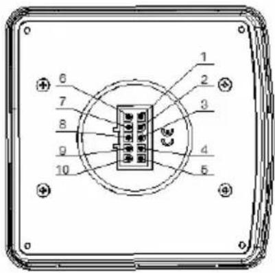
| 10-POLE REAR CONNECTOR | |
| PIN SIGNAL | |
| 1 + Battery | |
| 2 | |
| 3 - Battery | |
| 4 | |
| 5 | |
| 6 UP command | |
| 7 DOWN command | |
| 8 | |
| 9 | |
| 10 Magnetic sensor | |
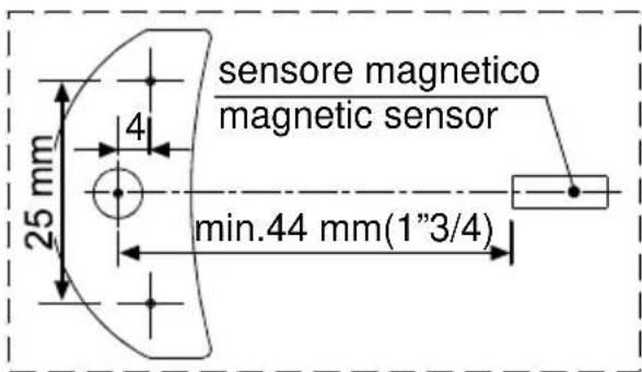
Chain counter and sensor hole
Starting up
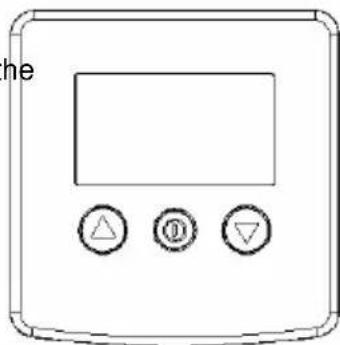
The chain counter features a graphic display and three keys: Ⓐ (ON), ▲ (UP) and ▼ (DOWN). There is also a buzzer that indicates the pressing of the keys or attracts the user's attention in particular conditions (alarm triggering).
The ON key switches on the display and enables the other two keys. It must be used to access the parameter setting menus. For selecting the parameters to be modified and to confirm the values set. The display backlight will switch off 30 seconds after the last command given (adjustable default time – see "BkLight Time").
The UP key commands the hoisting of the anchor and the DOWN key casts it. When the key is released, the action is stopped. During parameter setting, the two keys allow the User to move around the menu and vary parameter values.
When switched on, the instrument will make a beep and the following page will appear for a few seconds:

Once the initialisation procedure is complete, the main page will appear.

flowchart
graph LR
    A["STATUS"] --> B["Stop"]
    C["SPEED²"] --> D["0.0 ft/m"]
    E["COUNT"] --> F["0.0 ft"]
    G["MONITORING"] --> H["V=11.6"]
    I["ICONS"] --> J["metres / minute feet / minute"]
    K["metres / feet"] --> L["Icon"]
Where:
STATUS: indicates the status of the instrument and any failure.
SPEED': indicates the chain speed during hoisting or lowering in meters per minute or feet per minute.
COUNT: indicates the measurement of the chain lowered (in metres or feet).
MONITORING: indicates the power supply voltage.
ICONS: this is the part of the display bearing the icons that indicate the hoisting or casting of the anchor and any failure.
When the instrument is turned on for the first time, it will set up as programmed in the factory (see table).
| Parameter Default value | |
| Up Alarm 3.0 metres | |
| Auto Down Off | |
| BackLight Time 30 seconds | |
| Units of measurement Metres/centimetres | |
| Chain Measure 0.0 metres | |
| Barbotin Circumference 33 cm | |
| Sensor type unknown | |
| Keyboard Beep Yes | |
| Language Italian | |
| Works Hours 0 | |
| Rope_Chain Off | |
Chain counter setting menu
| Hold down the (ON) key for six seconds to access the instrument setting menu. The following page will appear on the display: |  |
| Use the (DOWN) and (UP) keys to move around the menu options. | 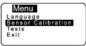 |
| Once you are positioned on the item to be modified press the (ON) key to confirm your choice. | |
| Use the (DOWN) or (UP) keys to move from one parameter to another. | |
| Once one is positioned on the parameter press the (ON) key to enable modification. | |
| According to the type of parameter, using the (DOWN) and (UP) keys it is possible to reduce/increase the value of the same or disable/enable the function. | |
| Once the modification has been performed, press the (ON) key to confirm. | |
| Using the (DOWN) key go to the Exit option and press the (ON) key again to return to the setting menu. The same procedure must be used to return to the main page. | |
Measurement menu
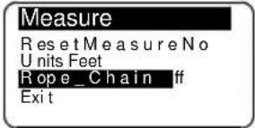
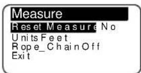
| MeasureReset Measur NoUnits FeetRope_Chain OffExit | |
| Use the ▼ (DOWN) or ▲ (UP) key to move around the parameters. | |
| Reset MeasurementResets the chain measurement value (0.0). | Select withID▼ = Yes ▲NoConfirm withID |
| UnitsSelects the unit of measurement:Feet/ inchesMetres / centimetres | Select withID▲ = Feet ▼MetresConfirm withID |
| Rope_ChainIt is possible to enable the function and set the value at which the sensor passes from rope to chain. Setting range 0.1 - 25.0 (metres or feet). This value corresponds to the chain length.To obtain this function, install sensor CMCT-01 (optional). | Select withIDSet value with▲▼Confirm withID |
| ExitTo return to the settings menu. | Confirm withID |
Alarm and functions menu
| Use the ▼ (DOWN) or ▲ (UP) key to move around the parameters. | |
| Up AlarmIt is possible to enable the function and establish the height at which the anchor-winch stops; after which it is only possible to give pulsed commands.Settable values: 1.0 - 1.5 - 2.0...5.0 (metres or feet). | Select withIDSelect value with▲▼Confirm withID |
| Auto DownEnables the automatic anchor lowering procedure, at the desired height, with the pressing (for at least 3 seconds) of the keys Ⓓ and ▼Settable value: 5 - 10 - 15...40 (metres or feet). | Select with➀Select value with▲ ▼Confirm with➁ |
| Load DefaultThis function allows the User to revert to the original factory default settings, thus erasing all settings memorised.This command must only be used in the event of programming errors. | Select with➁▼ = Yes ▲NoConfirm with➁ |
| ExitTo return to the settings menu. | Confirm with➁ |
Settings menu
| Use the ▼ (DOWN) or ▲ (UP) key to move around the parameters. | |
| ContrastBy enabling this function it is possible to start the display contrast programming procedure. | Select with➀Select value with▲▼Confirm with➁ |
| LightBy enabling this function it is possible to start the display luminous intensity programming procedure. | Select with➀Select value with▲▼Confirm with➁ |
| BackLight TimeThis function allows the user to set the backlight on time during which the display remains lit after the last command given (default value 30 seconds). | Select with➀Select value with▲▼Confirm with➁ |
| Keyboard BeepThis function allows the user to enable or disable the buzzer (emitted each time a key is pressed). | Select with➀▲= No ▼YesConfirm with➁ |
| ExitTo return to the settings menu. | Confirm with➁ |
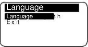
Language menu
 | |
| Use the ▼ (DOWN) or ▲ (UP) key to move around the parameters. | |
| LanguageThe user may select the display language: Italian, English, French, German, Spanish | Select withIDSelect value with▲▼Confirm withID |
| ExitTo return to the settings menu. | Confirm withID |
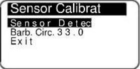
Sensor calibration menu
 | |
| Use the ▼ (DOWN) or ▲ (UP) key to move around the parameters. | |
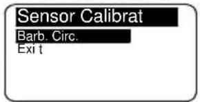
| Sensor DetectThis function has the purpose of calibrating the instrument according to the type of sensor installed (Standard or Project).The second screen indicates the time for a sensor period and type. | Select withIDSensor Detect.Press Up/Down Key to run the motor |
| Press▲or ▼ | |
| Sensor DetectPress Up/Down Key to run the motor0.400 sec.Sensor:Std | Sensor DetectPress Up/Down Key to run the motor0.400 sec.Sensor:Proj. |
| Confirm withID | |
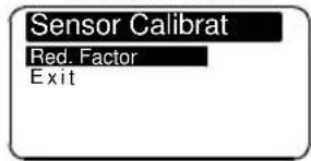
| Once the “Sensor Detection” function has recognised a “Standard” type sensor instead of a “Project” sensor, when the “Sensor Calibrat.” menu is entered again, the menu options will “configure” themselves according to the sensor detected. | |
Standard and X.. Project series sensor menu(magnet and sensor placed on barbotin)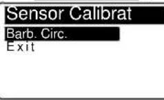 | 1000 – 1500 –2000 W Project series sensor menu(magnet and sensor placed on moto)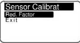 |
| Barbotin CircumferenceIn this row the user must enter the circumference of the gipsy (in centimetres of inches). Use the Table 1 provided to calculate the circumference.Settable values: centimetres or inches.Default value, 33 cm. | Reduction FactorIn this row the user must enter the reduction factor. See next Table 2 for the correct value to be enteredDefault value, 57. |
| Select with Select value with ▲ ▼ Confirm with | |
| ExitTo return to the settings menu. | Confirm with |
Table 1 - Standard and Project X.. series sensor (magnet and sensor placed on barbotin)
| Chain type | Number of recesses | Gipsy Circumference (cm) | Gipsy Circumference (inches) |
| 6 mm 9 34 13 | |||
| 7 mm 6 25 9 | |||
| 8 mm | 6 28 11 | ||
| 7 33* 13 | |||
| 8 38 15 | |||
| 10 mm | 5 31 12 | ||
| 6 36 14 | |||
| 12 mm | 5 36 14 | ||
| 6 43 17 | |||
| 13 mm 6 46 18 | |||
| 14 mm 5 42 16 | |||
| 3/8" BBB 7 38 15 | |||
| 3/8" HT 6 37 14 | |||
| 5/16" HT 7 36 14 | |||
| 1/2" BBB 6 40 16 | |||
| 1/2" HT 5 40 16 |
* factory setting of instrument
Table 2 - 1000 - 1500 - 2000W Project series sensor (magnet and sensor placed on motor
| Type | Gipsy Circumf. (cm) | Reduction ratio | Number of recesses | Chain type (mm-inches) | Reduction Factor |
| Project 1000 | 30 1:52 6 | 8-5/16"HT | 57* | ||
| 30 1:52 5 | 10 DIN 766 | ||||
| 31 1:52 5 | 10 ISO-3/8"HT | 59 | |||
| 34 1:52 9 | 6 | 65 | |||
| Project 1500 | 30 1:70 6 | 8-5/16"HT | 43 | ||
| 30 1:70 5 | 10 DIN 766 | 43 | |||
| 31 1:70 5 | 10 ISO-3/8"HT | 44 | |||
| 36 1:70 5 | 12 ISO-13 DIN 766-7/16"HT | 51 | |||
| Project 2000 | 39 1:75 6 | 3/8"HT | 52 | ||
| 40 1:75 6 | 3/8"Proof Coil | 53 | |||
| 41 1:75 6 | 10 DIN 766-3/8"BBB | 54 | |||
| 44 1:75 7 | 10 ISO | 58 | |||
| 45 1:75 5 | 14 ISO | 60 | |||
| 46 1:75 6 | 12 ISO-13 DIN 766 | 61 | |||
| 47 1:75 5 | 13 DIN 764 | 63 | |||
* factory setting of instrument
Check menu
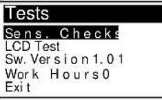 | |
| Use the ▼ (DOWN) or ▲ (UP) key to move around the parameters. | |
| Sensor ChecksThe purpose of this function is to check the state of the sensor:contact opencontact closed | Select with1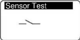 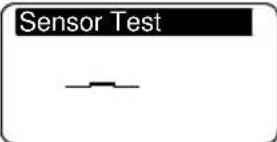 Confirm with2 Confirm with2 |
| LCD TestThis function switches on all the display's pixels thus making it possible to perform a check on them. | Select with1 Confirm with3 Confirm with3 |
| Software VersionIndicates the version of the software installed. | |
| Work HoursIndicates the hours of operation of the winch. | |
| ExitTo return to the settings menu. | Confirm with4 |
Instrument calibration
Before using the instrument the following parameters must be set:
- choice of unit of measurement (metres or feet);
- Setting of the Rope_Chain function (optional sensor type CMCT-01);
• detection of type of sensor (Standard or Project);
- gipsy diameter setting (default value 33 cm) or reduction factor (default value 57);
Standard and X.. Project series sensor menu
1000 – 1500 –2000 W Project series sensor menu
Use
Press the Ⓐ (ON) key to activate controls and to switch on the display lighting. The display lighting switches off 30 seconds after the last command given (adjustable default time – see "BkLight Time").
Press key (UP) to control the anchor ascending.
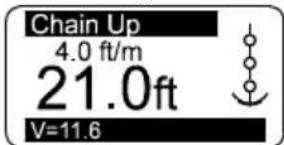
Press key(DOWN) to cast anchor.
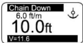
When any key is released (UP or DOWN) the corresponding action is stopped.
Measurement reset
To reset the measurement count simultaneously press the Ⓐ (ON) and the ▲ (UP) keys for at least three seconds.
Measurement reset may also be performed in the Measurement menu by selecting "Yes" in the Reset Measure row.
Automatic casting of the anchor
This function must be enabled in the Alarms and Functions menu (disabled by default).
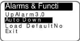
Select the row "Auto Down" and set the value at which the anchor must stop. Then press the Ⓐ (ON) and ▼ (DOWN) keys for at least three seconds. Once anchor casting has commenced, release the keys. For safety reasons it is however possible to interrupt automatic descent by pressing any instrument key.
Troubleshooting
| FAULT CAUSE CORRECTIVE ACTION | ||
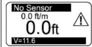 | Though UP or DOWN keys are pressed, the instrument doesn't receive any signal from the magnetic sensor for more than 5 seconds. | Check the sensor electric connections.Check if sensor operates properly. If not, replace it.Check the position of sensor and magnet on gipsy and their distance (3 mm).Check the operation of electric installation or anchor windlass. |
| Low Voltage0.0 ft/m0.0ftV=7.9 | The instrument's power supply voltage is lower than 10V. | Verify the battery charge or operation of the electrics system. |
Warranty
We guarantee our products from manufacturing defects for 2 years from the purchase date (purchase ticket or any other purchase proof will be requested). Guarantee does not include damages and breakage during the transport, damages and breakage due to faulty installation or improper use. Warranty is no longer valid when repairs or servicing have been made by unauthorized people or made with spare parts which are not original. Warranty does not include the complete replacement of the goods and refers exclusively to the replace of faulty pieces and necessary labour. It does not include transfer or transport expenses. The Customer will not ask for expenses refund.
Description
L'emballage contient:
MONTAGGIO A PARETE - WALL MOUNTING
natural_image
Exploded view diagram of a device showing internal components and assembly (no text or labels)MONTAGGIO A PANNELLO - PANEL MOUNTING
natural_image
Exploded view diagram of a smart home control panel showing internal components and connections (no text or labels)natural_image
Simple line drawing of a control panel with three buttons (triangle, circle, inverted triangle) and a display screen (no text or symbols)MONTAGGIO A PARETE - WALL MOUNTING
natural_image
Exploded view diagram of a device showing internal components and assembly (no text or labels)MONTAGGIO A PANNELLO - PANEL MOUNTING
natural_image
Exploded view diagram of a device showing internal components and assembly (no text or labels)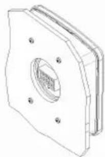
natural_image
Technical line drawing of a mechanical component with mounting holes and a central circular feature (no text or symbols)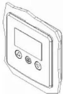
natural_image
Line drawing of a digital control panel with three buttons (no text or symbols)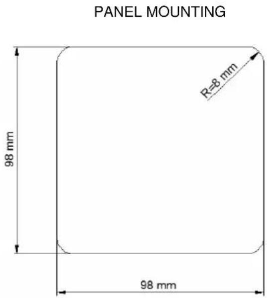
natural_image
Simple line drawing of a control panel with three buttons (triangle, circle, inverted triangle) and a blank display area (no text or symbols)MONTAGGIO A PARETE - WALL MOUNTING
natural_image
Exploded view diagram of a device showing internal components and assembly (no text or labels)MONTAGGIO A PANNELLO - PANEL MOUNTING
natural_image
Exploded view diagram of a smart home control panel with labeled components (no text or symbols)natural_image
Simple line drawing of a control panel with three buttons (triangle, circle, inverted triangle) and a blank display area (no text or symbols)- Descrizione
- General notes
- Components
- The package contains:
- Installation
- Installing the magnet on the anchor windlass
- Installing the magnetic sensor for vertical shaft anchor windlasses
- Installing the magnetic sensor for horizontal shaft anchor windlasses
- Installing the chain counter
- ALWAYS DISCONNECT THE BATTERY PRIOR TO INSTALLATION.
- Connections
- Chain counter and sensor hole
- Starting up
- Measurement menu
- Alarm and functions menu
- Language menu
- Sensor calibration menu
- Check menu
- Instrument calibration
- Use
- Measurement reset
- Automatic casting of the anchor
- Warranty
- Description
- L'emballage contient:
Brand : Lofrans
Model : Iris
Category : Metric counter