USER MANUAL 07L08200 BEST
natural_image
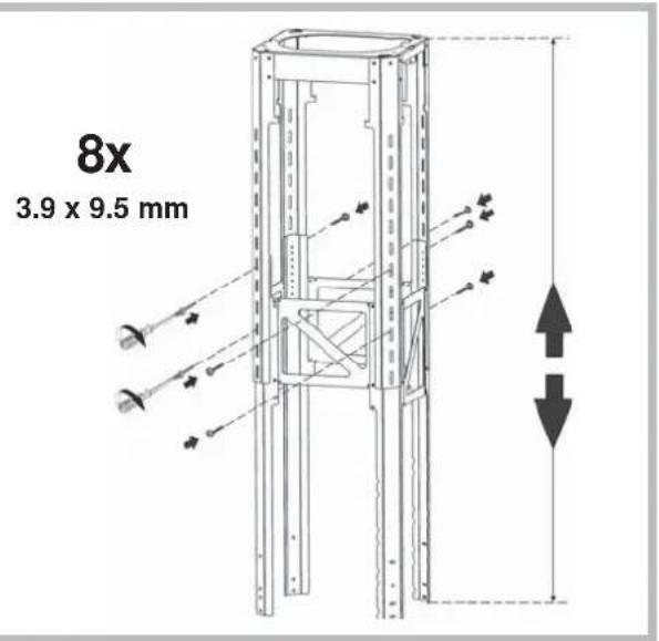
Technical line drawing of a multi-tiered vertical structural frame with mounting holes and internal compartments (no text or symbols)
natural_image
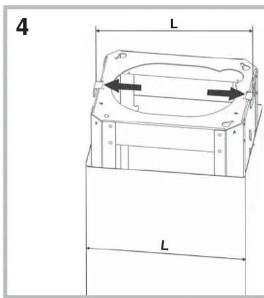
Line drawing of a three-tiered rectangular cabinet with circular vent slots and a label '1x' (no text or symbols on the cabinet itself)
natural_image
Simple line drawing of a cylindrical object with a flanged base and internal blades, labeled '4x' below (no text or symbols on the object itself)
natural_image
Illustration of a 4x4.5x60mm screw with threaded shaft (no text or symbols on the screw itself)
natural_image
Illustration of a solar panel with 1x multiplier label and a recycling symbol (no text or symbols on the panel itself)
natural_image
Two warning symbols: a black exclamation mark and a gray glove with white markings (no text or numbers present)

natural_image
Diagram of a mechanical or fluidic device with directional arrows indicating flow or movement (no text or symbols present)

natural_image
Diagram of a mechanical device with directional arrows indicating motion or force (no text or symbols)

EXT
natural_image
Diagram of a mechanical or fluidic device with directional arrows indicating flow or movement (no text or symbols present)
natural_image
Technical line drawing of a mechanical device with a handle and cable, no visible text or symbols
natural_image
Technical line drawing of a vertical cylindrical device with internal coiled structure and wiring (no text or symbols)
natural_image
Simple line drawing of a vertical cylindrical object with a downward arrow, placed on a base (no text or symbols)
natural_image
Technical line drawing of a mechanical device with internal components and an inset close-up showing wiring (no text or symbols)
14
19
15
flowchart
graph TD
    A["OFF"] --> B["A"]
    C["ON"] --> D["B"]
    E["OFF/-"] --> F["C"]
    G["ON/+"] --> H["D"]
    I["OFF/ON"] --> J["E"]
    K["L1"] --> L1
    L1 --> M["Green flame icon"]
20
16
21
flowchart
graph TD
    A["A"] --> B["B"]
    B --> C["C"]
    C --> D["E"]
    C --> E["OUT"]
    E --> F["OUT"]
17
22
18
23
24
29
flowchart
graph TD
    A["Sun icon"] --> B["TC1"]
    C["Light icon"] --> D["TC2"]
    E["Light icon"] --> F["TC3"]
    G["Light icon"] --> H["TC4"]
    I["Light icon"] --> J["TC5"]
    K["Light icon"] --> L["TC6"]
25
26
27
flowchart
graph TD
    A["Sun icon"] --> B["TC1"]
    C["Arrow icon"] --> D["TC2"]
    E["Arrow icon"] --> F["TC3"]
    G["Arrow icon"] --> H["TC4"]
    I["Arrow icon"] --> J["TC5"]
    K["Arrow icon"] --> L["TC6"]
28
natural_image
Diagram showing a solar panel being placed into a circuit board, with an arrow pointing to the component (no text or symbols present)
Illuminazione
natural_image
Diagram of a ceiling-mounted air duct system with a circular component inserted into the middle section (no text or labels)
natural_image
Line drawing of a kitchen chimney with an arrow indicating a component or assembly (no text or symbols present)
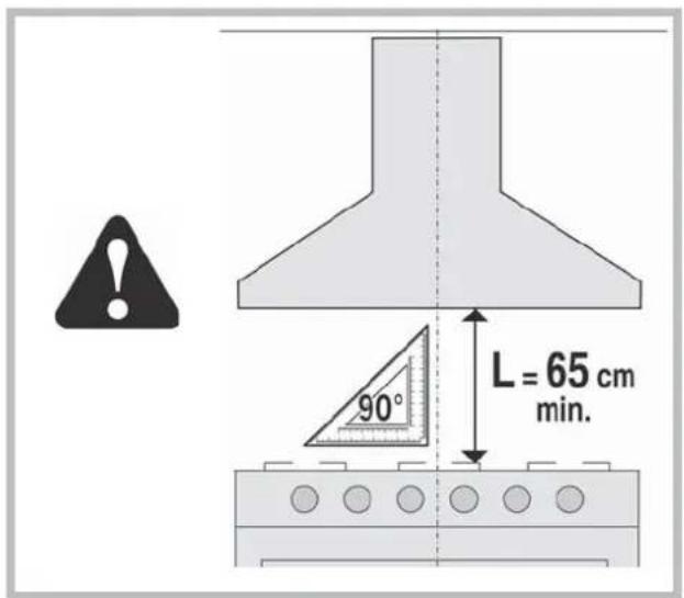
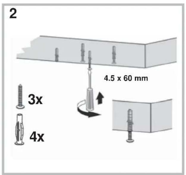
! The appliance must be installed by a qualified person in compliance with the instructions provided.

Wear gloves when carrying out installation and maintenance
operations.
If the supply cord is damaged, it must be replaced by the manufacturer, its service agent or similarly qualified persons in order to avoid a hazard.
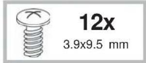
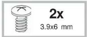
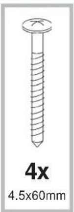
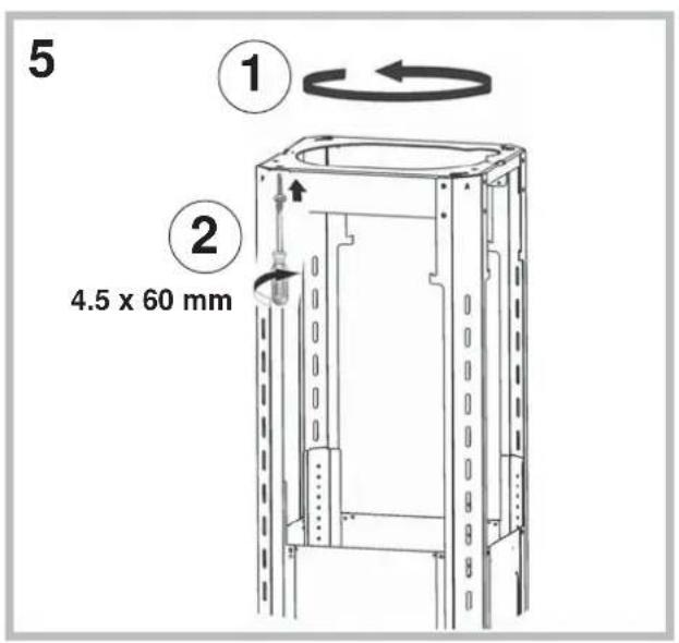
Warning: Failure to install the screws or fixing device in accordance with these instructions may result in electrical hazards.
The hood can look different to that illustrated in the drawings in this booklet. The instructions for use, maintenance and installation, however, remain the same.
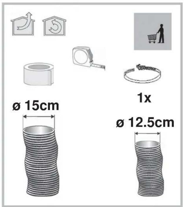
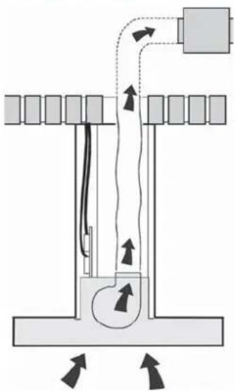
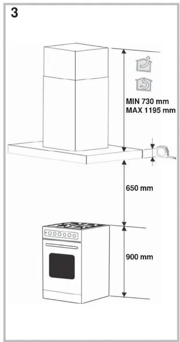
AIR VENT
(for ducting versions)
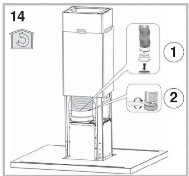
! Prepare the hole and the air vent duct (150 mm diameter).
! Use a duct of the minimum indispensable length.
! Use a duct with as few elbows as possible (maximum elbow angle: 90°).
! Avoid drastic changes in the duct cross-section.
! Use a duct with an as smooth as possible inside.
! The duct must be made of certified material.
! Do not connect the hood to smoke exhaust ducts for the products of combustion (boilers, fireplaces, stoves, etc).
! For the air vents comply with the provisions laid down by the competent authorities.
In addition, the air must not be evacuated through a hole in the wall unless specifically intended for this purpose.
! Fit air intakes in the room to prevent the hood from creating a negative pressure in the room (which must not exceed 0.04 mbar); if the hood is used at the same time as non-electrical equipment (gas-, oil- and charcoal-fired stoves, etc.) the exhaust gas may be sucked in by the heat source.
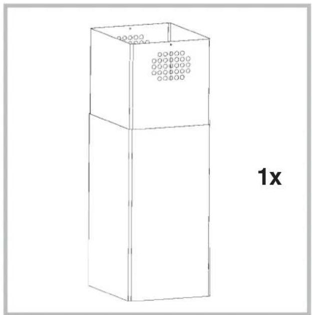
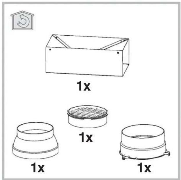
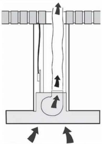
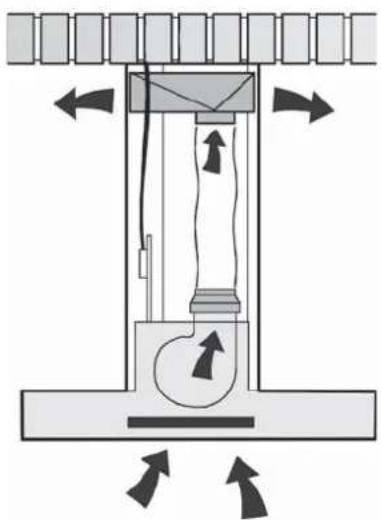
FILTERING OR DUCTING VERSION?
The hood may be in filtering or in ducting version. Decide from the outset which type is to be installed.
For better efficiency, we recommend installing the hood in the ducting version (if possible).

Ducting version
The hood purifies the air and evacuates it to the outside through an exhaust duct (diameter 150 mm).

Filtering version
The hood purifies the air and recycles the clean air back into the room. For this version, the following are required: 1 air baffle, 1 reducer, 1 charcoal filter. The upper flue air evacuation slots must be positioned at the top.
Only for hoods equipped with electronic control:
The 4th speed (intensive) is automatically lowered to 3rd speed after 5 minutes of operation to optimise energy consumption; in hoods with voltage 120V/60Hz this function is not active and the 4th speed is indicated by the letter b (Booster).
- If the hood is left on (lights and/or motor), after 10 hours in the absence of commands from the user, it will automatically switch to OFF condition with all services switched off. In hoods with voltage 120V/60Hz this function is not active.
- The Buzzer emits a "beep" each time that a command is set from the keyboard or remote control (optional).
- In the event of interruption of power during the hood, if you restore the hood in the OFF state, then the engine must be reactivate manually.
Only for hoods equipped with infrared sensor controls: The unit is equipped with infrared sensor controls that, if exposed to direct sunlight may not work properly; use curtains or other devices to shield the sunlight.
CONTROLS
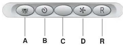
Controls of Fig. 14
A) Turns the LIGHTS off.
B) Turns the LIGHTS on.
C) Decreases speed down to minimum speed. If pressed for 2" the motor is turned off.
D) Activates the motor (calling the last speed used) and increases the speed until reaching maximum.
E) FILTER ALARM/TIMER RESET: when pressing the key during display of the filter alarm (motor off) its reset the hour counter. When pressing the key when the motor is running, the TIMER is activated and the hood will automatically be switched off after 5 minutes.
L1) The 4 green LEDs indicate the running speed.
L2) When the LED is red (motor off) it indicates the FILTER ALARM. When the LED is green (flashing) it indicates that the TIMER has been activated with the key E.
FILTER ALARM:
After 30h of operation, the LED L2 turns RED. It indicates that the grease filters need to be cleaned.
After 120h of operation, the LED L2 turns RED and flashes; It indicates that the grease filters need to be cleaned and the charcoal filters replaced. After cleaning the grease filters (and/or replacing the charcoal filters), restart the hour counter (RESET) by pressing the key E during display of the filter alarm.
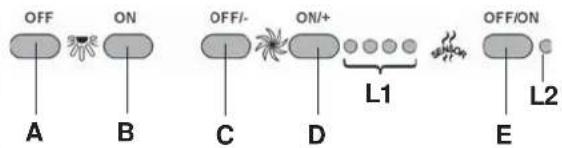
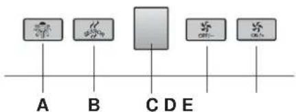
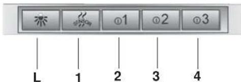
Controls of Fig. 15
A) Lights OFF: If pressed, lights go off.
B) Lights ON: If pressed, lights go on.P3) OFF/- Motor: Speed drop until minimum speed is reached. If pressed for 2", motor switches off. If pressed for 2" with FILTER RESET on HOUR count reset.
C) ON/+ Motor: Starts motor and increases motor speed until top speed is reached
D) ON/OFF: Switches Sensor off and on( AUTOMATIC or MANUAL mode). In Automatic mode, LED L2 is on and L1 shows operating speed In Manual mode, LED L2 is off.
L1) 4 LEDs 4 GREEN LEDs. Indicate set speed
L2) 4 LEDs GREEN indicates AUTOMATIC mode OFF indicates MANUAL mode RED indicates Filter Reset.
FILTER RESET: shown with Motor Off for 30": After 30h the LED L2 becomes steady RED. After 120h LED L2 becomes flashing RED Reset by means of C.
SENSITIVITY: In manual mode, by pressing E and D together, sensitivity mode is entered. The set sensitivity is indicated by the 4 green LEDs. By means of buttons C(-) and D(+) the desired sensitivity is set. By pressing P5 the sensitivity can be stored, with return to manual mode.
Attention: To prevent damaging the sensor, do not use silicone products near the hood!
Controls of Fig. 16
Key A: light switch.
Key B: first speed motor ON/OFF switch.
Key C: second speed switch.
Key D: third speed switch.
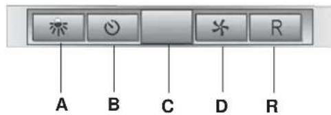
Controls of Fig. 17
Key A: light switch.
Key B: first speed motor ON/OFF switch.
Key C: second speed motor ON/OFF button.
Key D: third speed motor ON/OFF button.
E: motor on light.
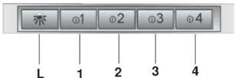
Controls of Fig. 18-19-20
Button A = turns the lights on/off.
Button B = turns the TIMER on/off: press once to turn the timer on, therefore, after 5 minutes, the motor cuts out (at the same time the selected speed blinks on the display); the timer remains on if the motor speed is changed.
Display C = - indicates the selected motor speed (from 1 to 4); - indicates Timer On when the number blinks; - indicates Filter Alarm when the central segments is on or blinking.
Button D = makes the motor work; pushing the button again, the speeds of the motor are sequentially selected from 1 to 4; keeping this button pressed for about 2 seconds shuts down the motor.
Button R = resets the grease filters or charcoal filters; when the filter alarm appears (i.e. when the central segment on the display goes on), the grease filters must be cleaned (30 hours of operation); when the central segment starts blinking, the grease filters must be cleaned and the charcoal filters replaced (120 hours of operation). Obviously, if the hood is not a filtering model and does not have a charcoal filter, clean the grease filters both when the central segment goes on and when it starts blinking. The filter alarm can be seen when the motor is off and for about 30 seconds. To reset the hour counter, keep the button pressed for 2 seconds while the alarm can be seen.
Controls of Fig. 21
AUTOMATIC OPERATION WITH SENSOR:
Key A : switches the lights on/off.
Key B : enables/disables "Automatic" function. When this function is selected, an "A" appears on the display C, and the speed of the motor increases or decreases depending on the smoke, odours and gas present in the kitchen.
Display C: - indicates the automatic operation of the sensor (the letter "A" appears);- indicates the motor speed selected automatically by the sensor;
indicates the filter alarm whenever the central segment is illuminated or flashing.
Key D : decreases motor speed / Reset; decreases motor speed to zero (stopping); in any case however, after approximately 1 minute, the hood resumes automatic operation at the speed set by the sensor. Whenever the key is pressed during the display of filter alarms, a RESET occurs, and the counting of the hours resumes again.
Key E : increases motor speed; in any case however, after approximately 1 minute, the hood resumes automatic operation at the speed set by the sensor.
Modification of sensor sensitivity: sensor sensitivity can be modified by operating as follows:
- stop the hood by pressing key B. - Simultaneously press keys D and E (the sensor's sensitivity index will appear on the display) - Pressing keys D or E, the sensor's sensitivity will either increase or decrease (1 : minimum sensitivity / 9: maximum sensitivity). - whenever the power supply is interrupted, the sensor will resume operation with a sensitivity index of 5. Warning: in order to avoid damaging the sensor, never use silicone products near the hood!
Key A : switches the lights on/off.
Display C : - indicates the motor speed selected (from 1 to 4); - indicates the operation of the Timer when the number is flashing; - indicates filter alarms whenever the central segment is illuminated or flashing.
Key D: decreases motor speed / Stop / Reset; decreases motor speed to zero (stopping). Whenever the key is pressing during filter alarm display, a RESET occurs, and the counting of the hours resumes again.
Key E : enables the motor / increases motor speed /TIMER. Pressing this key starts the motor (at the latest speed set); pressing the key again increases motor speed, while keeping the key pressed down for a few seconds enables the TIMER, and 5 minutes later the motor will stop (while the number of speed setting selected will simultaneously begin flashing on the display); the Timer will remain enabled if motor speed is changed. In order to disable the Timer, press the key again.
Controls of Fig. 22
Key L: light switch.
Key 1 : B = Motor ON/OFF switch - Speed I
Key 2: B = Motor ON/OFF switch - Speed I
Key 3: B = Motor ON/OFF switch - Speed I
Key 4: B = Motor ON/OFF switch - Speed I
Filter alarm: after about 30 hours of operation, with the motor off, the speed keys (keys 1, 2, 3 and 4) flash for 30 seconds to indicate the grease filters need cleaning. After cleaning the grease filters (and/or replacing the charcoal filters), restart the hour counter (RESET) by pressing key C during filter alarm display.
Timer 5'; the timer can be started (switch-off delayed by 5 minutes) by pressing one of the speed keys for 2 seconds(key 1, 2, 3 or 4) when the motor is running; the selected speed key starts flashing.
Controls of Fig. 23
Key L: light switch.
Key 1: activates/deactivates the sensor (AUTOMATIC or MANUAL mode). In Automatic mode the sensor is active and the speed of the motor increases or decreases depending on the smoke.- signals the filter alarm (with motor off)
Key 2: Motor ON/OFF switch - Speed I
Key 3: Motor ON/OFF switch - Speed II
Key 4: Motor ON/OFF switch - Speed III
Filter alarm: after about 30 hours of operation, with the motor off, the speed keys (keys 1, 2, 3 and 4) flash for 30 seconds to indicate the antigrease filters need cleaning. After cleaning the anti-grease filters (and/or replacingthe charcoal filters), restart the hour counter (RESET) by pressing one of the speed keys for 2 seconds during filter alarm display.
SENSOR SENSITIVITY: When the sensor is on, the hood automatically starts working when any smell, vapour, smoke or heat is detected during cooking. The sensor sensitively can be changed according to need. For example: very sensitive when using an electric hob or little sensitive when using a gas hob. Change the sensitivity by simultaneously pressing key L and key 1. The sensitivity selected will be set. Using the keys 2,3,4 you can set the desired sensitivity. Store the new sensitivity by pressing key 1. Attention: To prevent damaging the sensor, do not use silicone products near the hood!
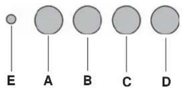
Controls of Fig. 24
Button A: Turns the lights on/off. If held down for about 2" when the filter alarm is active, it resets the hour counter.
Button B: Activates/deactivates the "Automatic" function.
Light S - Filter alarm: When the light comes on, it indicates that 30h of use have elapsed; it remains on for 30^ . When the light S flashes, it means that about 120h of operation have elapsed. The filter reset is indicated only when the motor is off, both in manual and automatic mode.
Automatic operation with sensor: when the button B is pressed, the automatic function is activated. This is indicated by the corresponding LED comingon. When the LED B flashes, it means that the sensor is waiting for
data.
Modifying sensor sensitivity: while in manual mode and with the motor off, simultaneously press the buttons B and C. At this point, the set sensitivity is indicated by the LED C, D or E coming on. To set the desired sensitivity press one of the buttons C, Dor E (min, med, max). Press B again to store it. Press button B once again to go to manual mode.
Operation as traditional hood: if in automatic mode, press the button B to change to manual mode; the LED B goes off. Press one of the buttons C, D or E to start the motor in 1st, 2nd or 3rd speed, respectively. Hold the same buttondown for 2'' to turn off the motor.
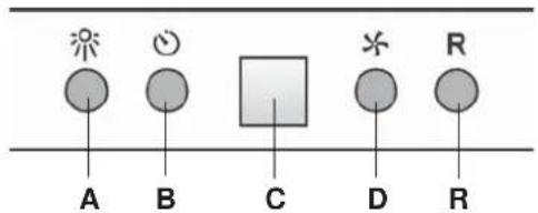
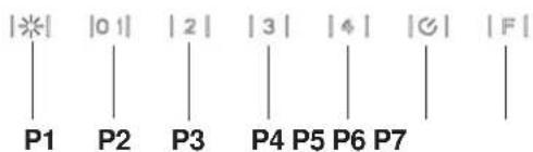
Controls of Fig. 25
P1: It turns on an off the light.
P2: It starts the engine setting it to the first speed (the icon is highlighted).
Other speed icons remain inactive.
P3: It starts the engine setting it to the second speed (the icon is highlighted). Other speed icons remain inactive.
P4: It starts the engine setting it to the third speed (the icon is highlighted). Other speed icons remain inactive.
P5: It starts the engine setting it to the fourth speed (the icon is blinking).
Other speed icons remain inactive. The maximum speed is set to be maintained for maximum 5 minutes, after this time the speed will be automatically adjusted to the third speed.
P6: It starts the timer (the icon is highlighted). By running the timer (5 minutes), the engine stops automatically after 5 minutes.
P7: FILTER ALARM. After 30 hours of operation the icon is highlighted to indicate that the filter should be cleaned.
After 120 hours of operation the icon is highlighted to indicate that the grease filter should be cleaned and the charcoal filters - replaced.
To RESET the alarm, press the icon while it is highlighted (or while it is blinking).
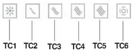
Controls of Fig. 26-27
Button TC1 (Lights): Switches main light ON/OFFWhen the main light is on, BL1 changes colour and becomes active.When the button is pressed for more than a second, it switches the courtesy lights (optional) on/off.
Button TC2 (Motor-V1): Motor ON/OFF - Activates the motor at 1st speed.
Button TC3 (Motor-V2) Activates the motor at 2nd speed.
Button TC4 (Motor-V3) Activates the motor at 3rd speed.
Button TC5 (Motor-V4) Activates the motor at 4th speed Maximum speed is timed at a maximum of 5 minutes, after which 3rd speed is set automatically. When the motor is active, the LED of the last selected button (TC2-TC5) active to signal which speed has been set.
Button TC6 (TIMER auto power off 5 min.) Activates the TIMER function at the speed that has already been selected. If the motor is NOT active, it switches on the motor at the 1st speed and activates the TIMER function. When the TIMER function is active, BL6 becomes active.
30h filter ALARM: after 30 hours of operation, an alarm switches on to signal the need for anti-grease filter cleaning. The filter alarm, when active, is displayed for 30 sec each time the motor is deactiva-ted:BL6 remains ON. During this period, it is possible to reset the alarm by pressing the TC6 button for longer than a second.
120h filter ALARM: after 120 hours of operation, an alarm switches on to signal the need for active carbon filter (optional) replacement. The filter alarm, when active, is displayed for 30 sec each time the motor is deactiva-ted:BL6 lighting blinking. During this period, it is possible to reset the alarm by pressing the TC6 button for longer than a second.
Work Time Limit: if the hood is left on (lights and/or motor), after 10 hours in the absence of commands from the user, it will automatically switch to OFF condition with all services switched off.
Buzzer: the Buzzer emits a "beep" each time that a command is set from the keyboard or remote control (optional).
Controls of Fig. 28-29
Button TC1 (Lights): Switches main light ON/OFFWhen the main light is on, BL1 changes colour and becomes active.When the button is pressed for more than a second, it switches the courtesy lights (optional) on/off.
Button TC2 (Motor-V1) Motor ON/OFF - Activates the motor at 1st speed.
Button TC3 (Motor-V2) Activates the motor at 2nd speed.
Button TC4 (Motor-V3) Activates the motor at 3rd speed.
Button TC5 (Motor-V4) Activates the motor at 4th speed Maximum speed is timed at a maximum of 5 minutes, after which 3rd speed is set automatically. When the motor is active, the LED of the last selected button (TC2-TC5) active to signal which speed has been set.
Button TC6 (Auto ASC) Activates/deactivates the automatic ASC function. In this mode, motor speed increases or decreases depending on the quantity of smoke and odours being produced under the hood. When the function is active, BL6 becomes active. Each time that the motor changes speed, either automatically or forced by the user, BL6 lighting blinking for a few seconds.
30h filter ALARM: After 30 hours of operation, an alarm switches on to signal the need for anti-grease filter cleaning. The filter alarm, when active, is displayed for 30 sec each time the motor is deactivated: BL6 remains ON. During this period, it is possible to reset the alarm by pressing the TC6 button for longer than a second.
120h filter ALARM: After 120 hours of operation, an alarm switches on to signal the need for active carbon filter (optional) replacement. The filter alarm, when active, is displayed for 30 sec each time the motor is deactivated: BL6 lighting blinking. During this period, it is possible to reset the alarm by pressing the TC6 button for longer than a second.
Buttons TC5 + TC6 (ASC sensitivity): ASC odour sensor sensitivity can be varied on 4 different levels as needed by pressing buttons TC5 and TCS simultaneously for more than 1 second. The motor must be OFF and automatic function NOT active. When sensitivity setting function is activated: all BL switch OFF (no display) then BL6 activates FIX. After 1 second, the BL2-BL5 LEDs will show the set sensitivity value, BL2 for lower sensitivity up to BL5 which indicates higher sensitivity. You can set a different value using corresponding keys TC2, TC3, TC4 or TC5. To save the new sensitivity, press TC6 or wait until the function deactivates automatically.
It can be varied on your keyboard (for cleaning) with a long press of the buttons TC1 and TC6 simultaneously. When the cleaning mode is active, the keys TC1 and TC6 remain lit. To exit cleaning is necessary to activate the buttons again TC1 and TC6 pressed simultaneously (long), or wait for 5 minutes.
Work Time Limit: if the hood is left on (lights and/or motor), after 10 hours in the absence of commands from the user, it will automatically switch to OFF condition with all services switched off.
Buzzer: the Buzzer emits a "beep" each time that a command is set from the keyboard or remote control (optional).
MAINTENANCE
! Before cleaning or maintenance cut the power.
Cleaning the hood
WHEN TO CLEAN IT: clean it at least every 2 months to prevent the risk of fire.
EXTERNAL CLEANING: use a cloth moistened in lukewarm water and neutral detergent (for painted hoods); use specific products for steel, copper or brass hoods.
INTERNAL CLEANING: use a cloth (or brush) soaked in denatured ethyl alcohol.
WHAT NOT TO DO: do not use abrasive or corrosive products (e.g. metal sponges, brushes, too hard brushes, very aggressive detergents, etc.)
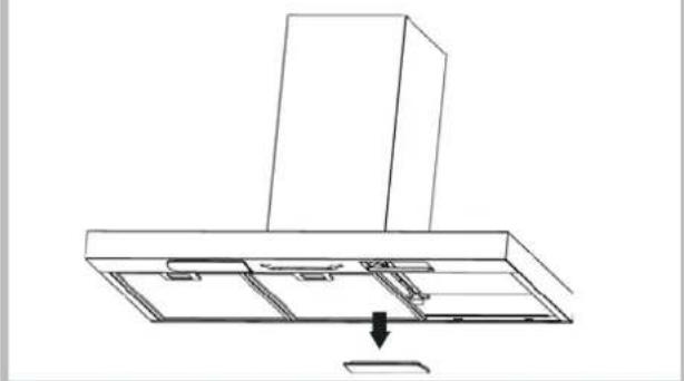
Cleaning the grease filters
WHEN TO CLEAN IT: clean it at least every 2 months to prevent the risk of fire, in according to use.
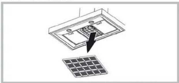
HOW TO REMOVE THE FILTERS: push the catch near the handle towards the rear of the hood and pull the filter downwards
HOW TO CLEAN THE FILTERS: hand wash or in the dishwasher using a neutral detergent. If washing in the dishwasher, possible discoloration of the filters does not in any way compromise their functioning.
Replacing the charcoal filter
(for filtering version only)
WHEN TO REPLACE IT: replace it at least every 6 months, in according to use.
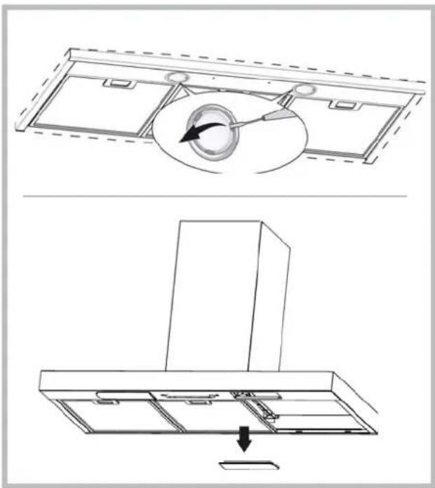
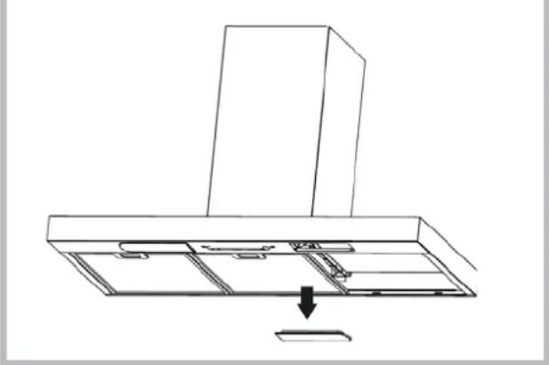
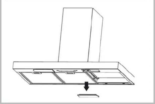
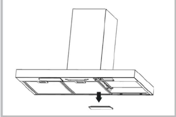
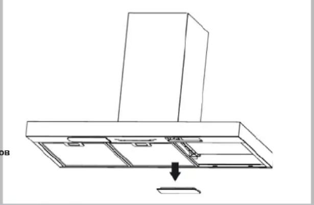
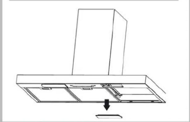
HOW TO REMOVE IT: If using the hood in the filtering version, the charcoal filter will have to be replaced. To switch off, pull the latch inward and rotate the filter downwards.
natural_image
Diagram showing a solar panel installation with an arrow pointing to the component (no text or symbols present)
Lighting
- Replace with light bulbs of the same type.
- If the light spot is damaged, it must be replaced only by the manufacturer, its service agent or similarly qualified persons in order to avoid a hazard.
natural_image
Technical line drawing of a kitchen air conditioner unit with internal components and airflow direction (no text or symbols)
MALFUNCTIONS
If something appears not to be working properly, do the following simple checks before calling Technical Service:
• If the hood is not working:
Check that:
- The power has not been disconnected.
- A speed has been selected.
• If the hood performs inefficiently:
Check that:
- The motor speed selected is sufficient for the amount of smoke and vapours released.
- The kitchen is sufficiently ventilated to allow air intake.
- The charcoal filter is not worn (hood in filtering version).
- If the hood has turned off during normal functioning:
Check that:
- The power has not been disconnected.
- the omnipolar disconnection device has not tripped.
This appliance is marked according to the European directive 2002/96/EC on Waste Electrical and Electronic Equipment (WEEE). By ensuring this product is disposed of correctly, you will help prevent potential negative consequences for the environment and human health, which could otherwise be caused by inappropriate waste handling of this product. The symbol on the product indicates that this product may not be treated as household waste. Instead it shall be handed over to the applicable collection point for the recycling of electrical and electronic equipment. Disposal must be carried out in accordance with local environmental regulations for waste disposal. For more detailed information about treatment, recovery and recycling of this product, please contact your local city office, your household waste disposal service or the shop where you purchased the product.
natural_image
Diagram showing a solar panel being inserted into an electronic device, with no text or symbols present.
Beleuchtung
natural_image
Technical line drawing showing a ceiling-mounted air duct assembly with a circular component and a mounted cabinet (no text or symbols)
BETRIEBSSTÖRUNGEN
natural_image
Diagram showing a device with internal components and a separate solar panel, no text or symbols present
Eclairage
natural_image
Diagram of a ceiling-mounted air duct system with a circular component inserted into the center (no text or symbols)
natural_image
Line drawing of a kitchen chimney with an arrow indicating downward motion (no text or symbols)
ANOMALIES DE FONCTIONNEMENT
natural_image
Diagram showing a device with a grid and an arrow pointing to it, next to a solar panel (no text or symbols present)
Iluminación
natural_image
Diagram of a ceiling-mounted air duct system with a circular component inserted into the middle section (no text or labels)
natural_image
Line drawing of a kitchen chimney with a downward arrow indicating a component or fixture (no text or symbols present)
A) Desliga as LUZES.
B) Acende as LUZES.
P1: Liga e desliga as LUZES
natural_image
Diagram showing a solar panel installation with an arrow pointing to a component (no text or symbols present)
Illuminação
natural_image
Diagram of a mechanical component with a circular component and directional arrow, no text or symbols present
natural_image
Line drawing of a kitchen chimney with an arrow indicating downward motion (no text or symbols)
natural_image
Diagram showing a solar panel installation with an arrow pointing to a component (no text or symbols present)
Verlichting
natural_image
Diagram of a ceiling-mounted air duct system with a circular component inserted into the center (no text or symbols)

natural_image
Line drawing of a kitchen chimney with a downward arrow indicating a component or fixture (no text or symbols present)
STORINGEN
natural_image
Diagram showing a solar panel installation with an arrow pointing to internal components (no text or symbols present)
Подсветка Подсветка
natural_image
Diagram of a ceiling-mounted air duct system with a circular component inserted into the middle section (no text or symbols)
natural_image
Line drawing of a kitchen chimney with an arrow indicating a component or fixture (no text or symbols present)
natural_image
Diagram showing a solar panel installation with an arrow pointing to internal components (no text or symbols present)
Belysning
natural_image
Technical line drawing showing a ceiling-mounted air duct assembly with a circular component and a mounted cabinet (no text or symbols)
DRIFTSFEJL
natural_image
Diagram showing a solar panel installation with an arrow pointing to the component (no text or symbols present)
Valaistus
natural_image
Technical line drawing showing a ceiling-mounted air duct assembly with internal components and a downward arrow indicating motion (no text or symbols)
TOIMINTAVIAT
natural_image
Diagram showing a solar panel being inserted into a device, with no text or symbols present.
Ljus
natural_image
Technical line drawing showing a ceiling-mounted air duct assembly with internal components and a downward arrow indicating motion (no text or symbols)
DRIFTFEL
natural_image
Diagram showing a solar panel installation with an arrow pointing to internal components (no text or symbols present)
φωτισμός
natural_image
Technical line drawing showing a ceiling-mounted air duct assembly with internal components and a downward arrow indicating motion (no text or symbols)
natural_image
Diagram showing a solar panel being inserted into an open panel, with a black arrow pointing to the component (no text or symbols present)
Illuminat
natural_image
Diagram of a ceiling-mounted device with a circular component inserted into a slot, showing no text or symbols.
natural_image
Line drawing of a kitchen chimney with a downward arrow indicating a component or fixture (no text or symbols present)
ANOMALII DE FUNCTIONARE
natural_image
Diagram showing a device with an arrow pointing to a grid array, no text or symbols present
Osvětlení
natural_image
Diagram of a mechanical component with an inset showing a circular feature and directional arrow (no text or symbols)
natural_image
Line drawing of a kitchen chimney with an arrow pointing to a component (no text or symbols)
ABNORMÁLNÍ FUNKCE
natural_image
Diagram showing a solar panel installation with an arrow pointing to the internal components (no text or symbols present)
Razsvetljava
- Zamenjajte žarnico istega tipa.
natural_image
Technical line drawing showing a ceiling-mounted air duct assembly with internal components and a downward arrow indicating motion (no text or symbols)
CHYBY PRI PREVÁDZKE
natural_image
Diagram showing a solar panel installation with an arrow pointing to internal components (no text or symbols present)
Aydýnlatma
natural_image
Technical line drawing showing a ceiling-mounted air duct assembly with internal components and a downward arrow indicating motion (no text or symbols)
ÇALISMA ARIZALARIB