
GW96891 - Dimmer Gewiss - Free user manual and instructions
Find the device manual for free GW96891 Gewiss in PDF.
| Brand | Gewiss |
| Model | GW96891 |
| Product type | Twilight dimmer with weekly clock |
| Category | Dimmer (twilight switch) |
| Power supply | 250 V AC, 50-60 Hz |
| Breaking capacity (resistive load) | 16 A / 250 V AC |
| Breaking capacity (inductive load cos φ 0.6) | 10 A / 250 V AC |
| Max power incandescent/halogen lamp | 2600 W |
| Max power fluorescent lamp | 1000 W |
| Brightness adjustment range | 2 - 500 lux |
| Adjustable delay | 0 - 100 s (on and off) |
| Number of channels | 1 |
| Time memory slots | 50 |
| Power reserve | 3 years (factory setting) |
| Clock accuracy | ± 1 s/day at +20°C |
| Protection degree (control unit) | IP20 |
| Protection degree (sensor) | IP65 |
| Ambient temperature (control unit) | -10°C to +55°C |
| Ambient temperature (sensor) | -30°C to +70°C |
| Mounting | On DIN rail, dry rooms only |
| Sensor cable cross-section (min.) | 2 x 0.75 mm², max length 100 m |
| Safety | Installation by qualified electrician; DANGER OF DEATH BY ELECTRIC SHOCK |
| Main functions | Twilight switch, weekly clock, adjustable delay, auto and manual modes, programming |
| Maintenance | No specific maintenance; waste disposal according to regulations |
| Spare parts | External sensor included; no spare parts supplied |
Frequently Asked Questions - GW96891 Gewiss
User questions about GW96891 Gewiss
0 question about this device. Answer the ones you know or ask your own.
Ask a new question about this device
Download the instructions for your Dimmer in PDF format for free! Find your manual GW96891 - Gewiss and take your electronic device back in hand. On this page are published all the documents necessary for the use of your device. GW96891 by Gewiss.
USER MANUAL GW96891 Gewiss
2


Messa in funzione
Display
Safety instructions and product description.... 17
Product description
Intended use
Installation and assembly 18
Assembly on DIN-rail
Connecting and mounting the brightness sensor
Wiring diagram
Set-up
Operation and adjustment 20
Display and function keys
Menu structure
Initial start-up – Language menu
Date and time setting
Daylight Saving Time
New program
View and edit programs
Delete program
Switching mode
Disposal / Recycling 27
Technical data 28

DANGER! RISK OF ELECTRIC SHOCK!
Connection and mounting must be realized by a professional electrician!
- Please observe the national regulations and safety instructions.
- Interferences and changes to the device will invalidate the warranty and guaranty rights.
- Minimum diameter of the flexible lines for the terminals: 1 mm 2 . Maximum diameter: 4 mm 2 .
Read and observe these instructions to guarantee a perfect function of the device and a safe operation.
Product description
Photoelectric switch
- 1 channel.
- Adjustable ON/OFF switching delay: 0-100 sec.
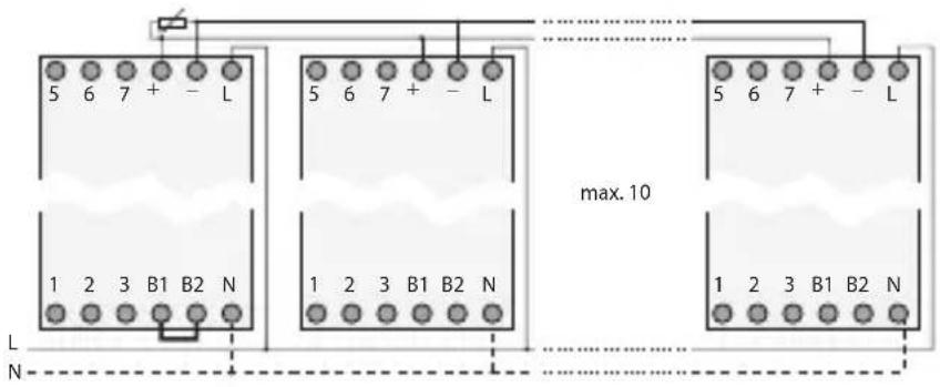
- Up to 10 devices can be combined to build a light control system with just one brightness sensor.
- With weekly timer.
Intended use
- The photoelectric switch is used for:
- lighting in private homes and commerce
- advertising
- street lighting
- shop window lighting
- car park lighting
-
controlling shutters and blinds
-
Mounting only on DIN rails.
- Intended only for use in dry areas!
INSTALLATION AND ASSEMBLY

DANGER! RISK OF ELECTRIC SHOCK!
Connection and mounting must be realized by a professional electrician!
Assembly on DIN-rail
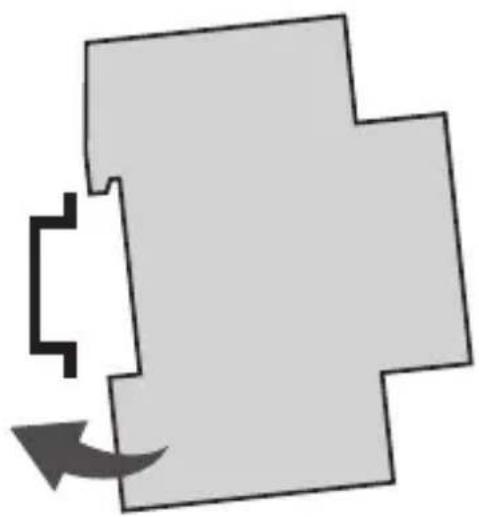
Put the device slightly inclined on top of the rail. Then push it backwards until it engages.
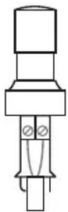
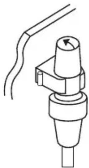
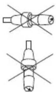
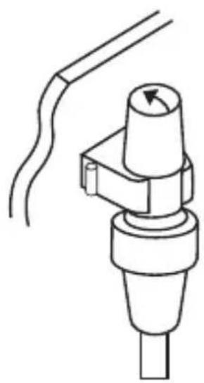
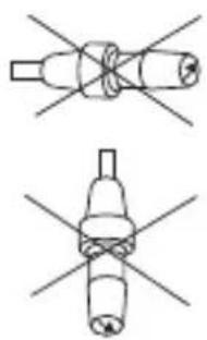
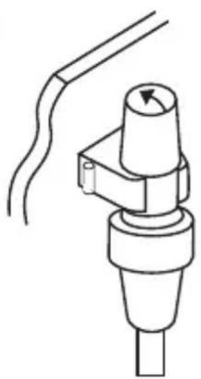
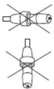
Connecting and mounting the brightness sensor
1
2
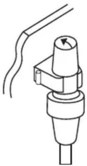

- Length of the connecting cable: max 100 m
• Line cross-section: min 2 x 0 75 mm²
INSTALLATION AND ASSEMBLY
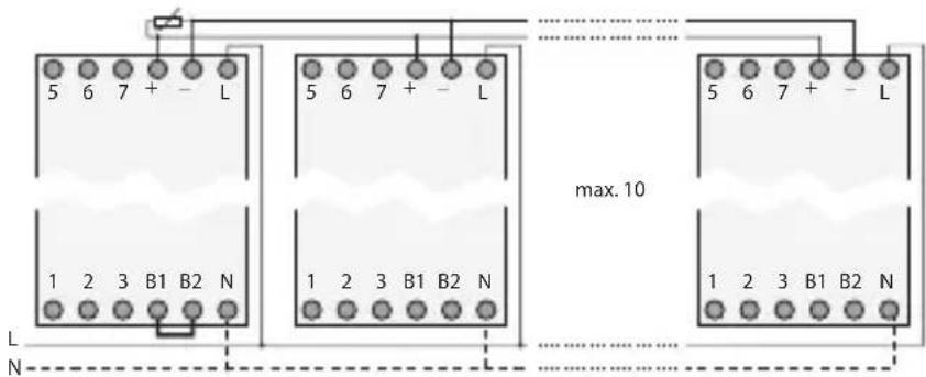
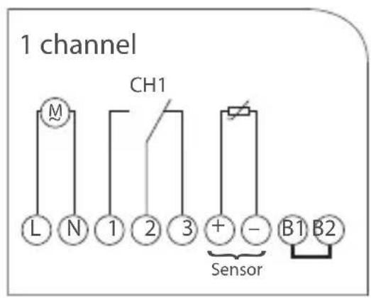
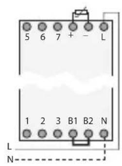
Wiring diagram

If you connect the sensor to the + and - terminals, you must connect a jumper between terminals B1 and B2.
If you operate several devices on one sensor, this jumper may only be used for one device.
Set-up
The device - twilight switch and timer - only activates the output (terminals 1 and 5) when all three conditions are fulfilled:
- brightness is lower than the adjusted value
• the adjusted delay time has passed - the timer is set to = = 0N
OPERATION AND ADJUSTMENT
Display and function keys
- The central line of the display, in which the adjusted values and selected menu items are displayed, is displayed larger.
- Flashing means that an entry is required If you do not enter anything within two minutes, the timer switches back to automatic operation.
- The programs are maintained when resetting You need to readjust date and time Press the reset button using a blunt object (ball-point pen).
Adjusting the lux value
Turn the rotary switch to adjust the desired lux value (2-500 lx).
The LED is lighted as soon as the surrounding brightness is lower than the adjusted lux value.
Adjusting the delay time
Turn the rotary switch to adjust the desired delay time (0-100 sec).
This reduces incorrect switching due to short-term external light effects, such as lightning, etc.
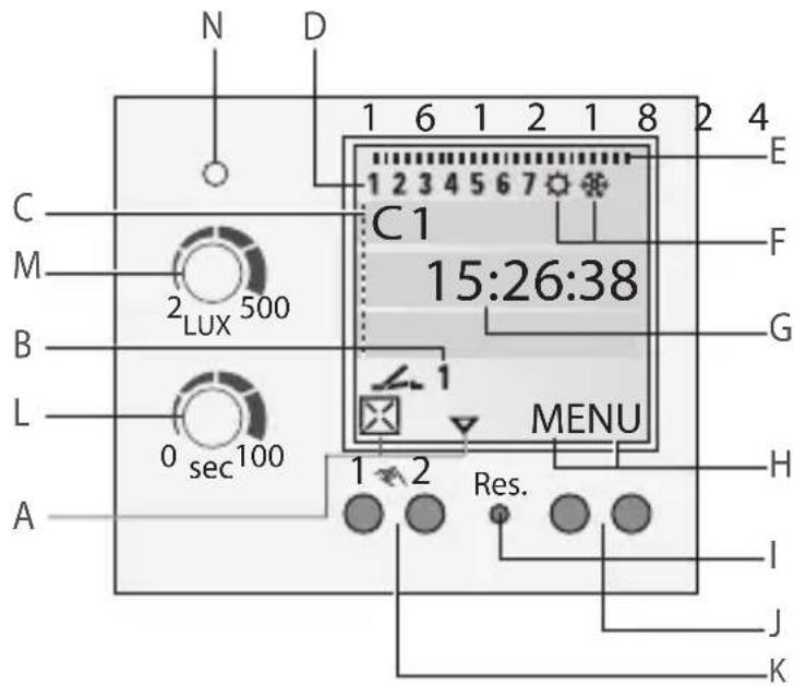
Display
A Function displays of the two left-hand buttons
B Channel status displays
OPERATION AND ADJUSTMENT
C 3-line LCD display
D Day-of-week display
E Overview of daily switching program
F Indicates Dailight Saving Time
G Operating voltage (permanently lit dots)
Reserve power operation (dots flash)
H Function displays of the two right-hand buttons
Tasti/Interruttori
I Reset
J Right-hand buttons
K Left-hand buttons with manual switch function in Automatic Mode
L Button for ON/OFF switching delay
M Button for adjusting the Lux value
N Switching state display without delay
△ scroll up in menu
▼ scroll down in menu
☒ Select/reject suggestion
√ Select/accept suggestion
+ Press briefly = +1 / Press and hold (approx 2 sec) = +5
- Press briefly = -1 / Press and hold (approx 2 sec) = -5
Functions of the right-hand buttons:
MENU Exits the Automatic mode and enters the Programming mode
ESC Press briefly = one step back
Press and hold (approx. 2 sec) = return to Automatic mode
OK Make selection and apply
EDT Change request in "Review mode"
NO Do not execute command
YES Execute command
DEL Delete
OPERATION AND ADJUSTMENT
Menu structure
![graph TD A["MENU"] --> B["PROGRAM"] B --> C["DAYLIGHT"] C --> D["12H 24H"] D --> E["24H"] E --> F["AM PM"] B --> G["NEW"] B --> H["DELETE"] B --> I["REVIEW"] C --> J["AUTO"] C --> K["NO"] C --> L["CALIBRAT"] M["LANGUAGE"] --> N["DATETIME"] O["ENGLISH"] --> N P["FRANCAIS"] --> N Q["..."] --> N](/content/2026/03/429042/images/637e250a9a7fd424f84a7597066ea27bedfb6d35af8aad04dba06382a9f2d489.jpg)
Initial start-up – Language menu
When delivered, the timer is in automatic mode with preset time, date (CET) and menu in English.
Press the Menu button to make settings. Then select the desired setting.
![graph TD A["MENU"] --> B["LANGUAGE"] B --> C["ENGLISH"] C --> D["OK"] C --> E["OK"]](/content/2026/03/429042/images/6b72a79c5cb20d164725f0c7b8be137b0304e5eb38ca7e5755077bbd74319985.jpg)
OPERATION AND ADJUSTMENT
Date and time setting
![graph TD A["MENU"] --> B["DATETIME"] B --> C["YEAR"] C --> D["MONTH"] D --> E["DAY"] E --> F["HOURS"] F --> G["MINUTES"] G --> H["OK"] style A fill:#f9f,stroke:#333 style H fill:#f9f,stroke:#333](/content/2026/03/429042/images/7cb26d6f158d61998fec833fc4fcaad95c7669bddaddcc96f2fa334effcee76d.jpg)
In the menu 12H 24H you can choose between AM/PM and 12/24-hour announcement.
Daylight Saving Time
![graph TD A["MENU"] --> B["DAYLIGHT"] B --> C["CALIBRAT"] C --> D["SU STRT MONTH"] D --> E["SU STRT DAY"] E --> F["WI STRT MONTH"] F --> G["WI STRT DAY"] G --> H["SU WI 2103:3110 CALIBRAT"] H --> I["OK"] I --> J["OK"] J --> K["OK"] K --> L["OK"] L --> M["OK"] M --> N["OK"] N --> O["OK"] O --> P["OK"]…](/content/2026/03/429042/images/174954603bb7c74fb507282797e79458488be6eb9a5d7bb806eb4f3068ff6b6b.jpg)
The following settings are possible:
AUTO
Factory presetting of the published calendar dates (CET). This is automatically recalculated for each year.
NO
No switchover.
CALIBRAT
Programming. The start date of the summer time and winter time must be entered for this purpose. The factory presetting is overwritten. The programmed summer/ winter time is automatically recalculated for each year. The changeover takes place on the same specified day of the week in the same week of each month.
OPERATION AND ADJUSTMENT
New program
![graph TD A["MENU"] --> B["PROGRAM"] B --> C["NEW"] C --> D["SELECT CHL"] D --> E["DAY CHL ON"] E --> F["H CHL ON"] F --> G["MIN CHL ON"] G --> H["DAY CHL OFF*"] H --> I["H CHL OFF"] I --> J["MIN CHL OFF"] J --> K["SAVED P01 P02"]](/content/2026/03/429042/images/301f745829784d97e8562069b83c83fa7e459c47877a5359c7e98a92755eb57c.jpg)
*) Available only if individual days have been selected for the ON command.
- Press the Menu button.
- Confirm PROGRAM by pressing OK.
- Confirm NEW by pressing OK. ➢ Free memory space is briefly displayed.
ON command:
- Select the desired days ☒ and confirm by pressing √. → OK
- Enter the hours (+/-) → OK
- Enter the minutes (+/-) → OK
OFF command:
- If requested, select the desired days ☒ and confirm by pressing √.→ OK
- Enter the hours (+/-) → OK
- Enter the minutes (+/-) → OK
The program is saved.
OPERATION AND ADJUSTMENT
View and edit programs
![graph TD A["MENU"] --> B["PROGRAM"] B --> C["ON"] C --> D["OFF"] D --> E["P01"] E --> F["REVIEW"] F --> G["OK"] G --> H["P02"] H --> I["EDT/OK"] I --> J["OK"] J --> K["P01"] K --> L["EDT/OK"]](/content/2026/03/429042/images/e45c65dc2c586bbfd726bdf498570133269d641ad729650a971c2f0458087739.jpg)
- Press to scroll through the different program steps.
- Press OK to get to the next program.
- Press EDT to edit a program.
This procedure is similar to creating a new program.
Delete program
DELETE ALL PROGRAMS
- Press YES to delete all programs.
- Press NO to delete individual programs.
![graph TD A["MENU"] --> B["PROGRAM"] B --> C["DELETE"] C --> D["ALL"] D --> E["CONFIRM"] E --> F["OK"] E --> G["OK"] E --> H["YES"] E --> I["YES"]](/content/2026/03/429042/images/5a5829bb0030a7f54bb15416e369a728e3292fcb9a9d9c67c291e9fdce44e22c.jpg)
OPERATION AND ADJUSTMENT
DELETE INDIVIDUAL PROGRAMS
- For deleting individual programs, all belonging program steps are deleted (e.g. P01 ON and P02 OFF).
- Press OK to get to the next program.
![graph TD A["DELETE"] --> B["ALL"] B --> C["ON"] C --> D["PO1"] D --> E["CONFIRM"] E --> F["OK"] E --> G["NO"] E --> H["DEL/OK"] E --> I["YES"]](/content/2026/03/429042/images/24e405584674a30ad57ddb765fec737b15eaa06d46954d04d593d549ce3a59fe.jpg)
Switching mode
- Manual switch: duration ON / duration OFF / automatic mode.
- Left button = channel 1.
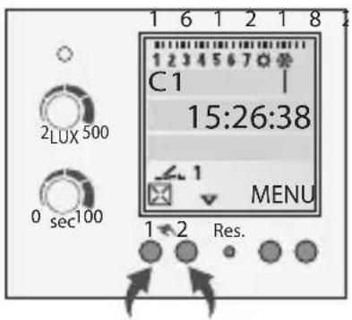
Press 1x = FIX ON = duration ON Press 2x = FIX OFF = duration OFF Press 3x = automatic mode
Channel status displays
= channel ON = channel OFF
There is no display in automatic mode.
DISPOSAL / RECYCLING
Dispose of the packing material correctly according to legal requirements and regulations.
Observe the following notes for disposing of defective system components or the system after its service life:
- Dispose of appropriately, i.e. separating the parts to be disposed of according to material groups.
- Do not throw electrical and electronic components in the bin Bring these parts to the recycling centers.
- Always ensure the environmentally sound disposal conform to the state-of-the-art environment protection, recycling and disposal engineering.
TECHNICAL DATA
AC switching capacity:
| Ohmic load | 16 A / 250 V AC |
| Inductive load cos φ0,6 | 10 A / 250 V AC |
| Incandescent/halogen lamp load | 2600W |
| Fluorescent lamp | 1000W |
| Rated load AC1 / AC15 | 3700W / 750W |
Ambient temperature:
| Control unit / Brightness sensor | -10°C... + 55°C / -30°C... + 70°C |
Protection type
| Control unit / Brightness sensor | IP 20 / IP 65 |
Photoelectric switches:
| Adjustment range | 2 lx – 500 lx |
| Switching delay | adjustable: appr 0-100s ON/0-100s OFF |
Time switch:
| Memory spaces | 50 |
| Accuracy | typ ± 1 s/day at +20°C |
| Running reserve | 3 years from factory |
FRANÇAIS
SOMMAIRE
pag.
2
Ecran
G Tension de service (points permanents)
2
2
According to article 9 paragraph 2 of the European Directive 2004/108/EC and to article R2 paragraph 6 of the Decision 768/2008/EC, the responsible for placing the apparatus on the Community market is:
GEWISS S.p.A Via A. Volta, 1 - 24069 Cenate Sotto (BG) Italy Tel: +39 035 946 111 Fax: +39 035 945 270 E-mail: qualitymarks@gewiss.com


+39 035 946 111
8.30 - 12.30 / 14.00 - 18.00 lunedì ÷ venerdì - monday ÷ friday

+39 035 946 260

- MESSA IN FUNZIONE
- DISPLAY
- SAFETY INSTRUCTIONS AND PRODUCT DESCRIPTION.... 17
- INSTALLATION AND ASSEMBLY 18
- OPERATION AND ADJUSTMENT 20
- DISPOSAL / RECYCLING 27
- TECHNICAL DATA 28
- DANGER! RISK OF ELECTRIC SHOCK
- PRODUCT DESCRIPTION
- PHOTOELECTRIC SWITCH
- INTENDED USE
- INSTALLATION AND ASSEMBLY
- ASSEMBLY ON DIN-RAIL
- CONNECTING AND MOUNTING THE BRIGHTNESS SENSOR
- WIRING DIAGRAM
- SET-UP
- OPERATION AND ADJUSTMENT
- DISPLAY AND FUNCTION KEYS
- ADJUSTING THE LUX VALUE
- ADJUSTING THE DELAY TIME
- TASTI/INTERRUTTORI
- FUNCTIONS OF THE RIGHT-HAND BUTTONS
- INITIAL START-UP – LANGUAGE MENU
- DATE AND TIME SETTING
- DAYLIGHT SAVING TIME
- AUTO
- NO
- CALIBRAT
- NEW PROGRAM
- VIEW AND EDIT PROGRAMS
- DELETE PROGRAM
- DELETE ALL PROGRAMS
- DELETE INDIVIDUAL PROGRAMS
- SWITCHING MODE
- CHANNEL STATUS DISPLAYS
- DISPOSAL / RECYCLING
- TECHNICAL DATA
- FRANÇAIS
- SOMMAIRE
- ECRAN
Brand : Gewiss
Model : GW96891
Category : Dimmer