
GW90815 - Electrical control device Gewiss - Free user manual and instructions
Find the device manual for free GW90815 Gewiss in PDF.
| Product Type | GSM remote control device for KNX/EIB system |
| Brand | Gewiss |
| Model | GW90815 |
| Dimensions | 6 DIN modules (width 108 mm) |
| Power Supply | 230 VAC + 3 rechargeable NiMh AAA backup batteries (recommended capacity ≥ 800 mAh) |
| Power Consumption | 2 W |
| Bus current consumption | 1.5 mA |
| Communication | Quad-band GSM network, SMS send/receive |
| Main Functions | Control of 8 general outputs, management of 1/8/16-bit inputs, thermal regulation, anti-theft control, sending status and alarm SMS |
| Configuration | Via ETS software (USB connection) or by SMS |
| Connectivity | KNX/EIB bus, 1 USB type B port, SMA antenna connector |
| Antenna | External with 1.5 m extension cable, double-sided adhesive fixing |
| Display | Green LED (device status), red/green/yellow LED (GSM module status), red LED (physical address programming) |
| Operating Temperature | -5 °C to +45 °C |
| Storage Temperature | -25 °C to +70 °C |
| Relative Humidity | Up to 95% without condensation |
| Protection Degree | IP20 |
| Maintenance and Cleaning | Clean with a dry cloth |
| Safety | Installation by qualified personnel, comply with IEC 64-8 standard, 4-character password for SMS access |
| Package Contents | Device, antenna, 1.5 m extension cable, bus terminal, cover with screws, 2 double-sided adhesive tapes, manual |
| Reference Standards | Low Voltage Directive 72/23/EEC, EMC 89/336/EEC, EN50428, EN50090, ETSI EN301 489-7, ETSI EN301 511 |
Frequently Asked Questions - GW90815 Gewiss
User questions about GW90815 Gewiss
0 question about this device. Answer the ones you know or ask your own.
Ask a new question about this device
Download the instructions for your Electrical control device in PDF format for free! Find your manual GW90815 - Gewiss and take your electronic device back in hand. On this page are published all the documents necessary for the use of your device. GW90815 by Gewiss.
USER MANUAL GW90815 Gewiss
- unsigned [0..255]
- signed [-128.. +127]
• valore percentuale [0%.. 100%].
Invio valori 16 bit
- unsigned [0..255]
- signed [-128.. +127]
• valore percentuale [0%.. 100%].
- unsigned [0 .. 65535]
• signed [-32768.. +32767] - floating point.
natural_image
Pure diagram of a rectangular device with internal components and directional arrows, no text or symbols present.natural_image
Technical diagram of an electronic device showing internal components and wiring (no text or labels)natural_image
Mechanical assembly diagrams showing two views of a device with arrows indicating force or movement (no text or symbols present)INSTALLAZIONE
natural_image
Diagram of a mechanical device with a cylindrical tool inserted into a slot, showing no text or symbols.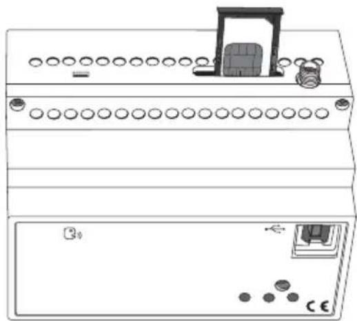
natural_image
Line drawing of a dual-panel electronic device with circular ports and a front panel (no text or symbols)natural_image
Diagram of a dual-chamber electronic device with ports and connectors (no text or symbols)Messa in servizio
natural_image
Line drawing of an electronic device connected to a laptop via cable, showing ports and wiring (no text or symbols)COLLEGAMENTO PC - REMOTIZZATORE
MAIUSCOLE E MINUSCOLE
COMANDI USCITE A 8 BIT
COMANDI USCITE A 16 BIT
INGRESSI KNX A 1 BIT
INGRESSI KNX A 8 BIT
INGRESSI KNX A 16 BIT
Warnings for KNX/EIB installation 34
Warnings for installation phase ....34
Verification of GSM signal cover 34
SIM 35
Assembly on the DIN rail 35
Electrical connections 36
Connection examples 37
SIM insertion 38
PROGRAMMING
Aerial position and connection 39
Commissioning 39
Physical address programming 39
Configuration procedures 40
Password 40
PC configuration 40
Interaction and configuration via SMS 41
Basic configuration 42
Configuration via SMS 42
Final Inspection 46
IN SERVICE
Remote control via SMS 47
Local indications 49
Emergency blackout function 49
Cleaning the remote control unit 49
Replacing the batteries .50
Recharging the SIM 50
TECHNICAL DATA ....51
Default values ....51
GENERAL INFORMATION
Warning! The safety of this appliance is only guaranteed if all the instructions given here are followed scrupulously. These should be read thoroughly and kept in a safe place. The Chorus products must be installed in compliance with the requisites of standard CEI 64-8 for devices for domestic use and similar, in non-dusty atmospheres and where special protection against water penetration is not required.
The GEWISS sales organisation is at your disposal for clarifications and technical information.
Gewiss SpA reserves the right to make changes to the product described in this manual at any time and without giving any notice.
Pack content
n. 1 GSM EIB remote control unit - DIN rail
n. 1 Aerial
n. 1 Aerial extension cable 1.5 m
n. 1 Bus terminal
n. 1 Cover with screw
n. 2 Double-sided adhesives
n. 1 Installation and user manual
Summary
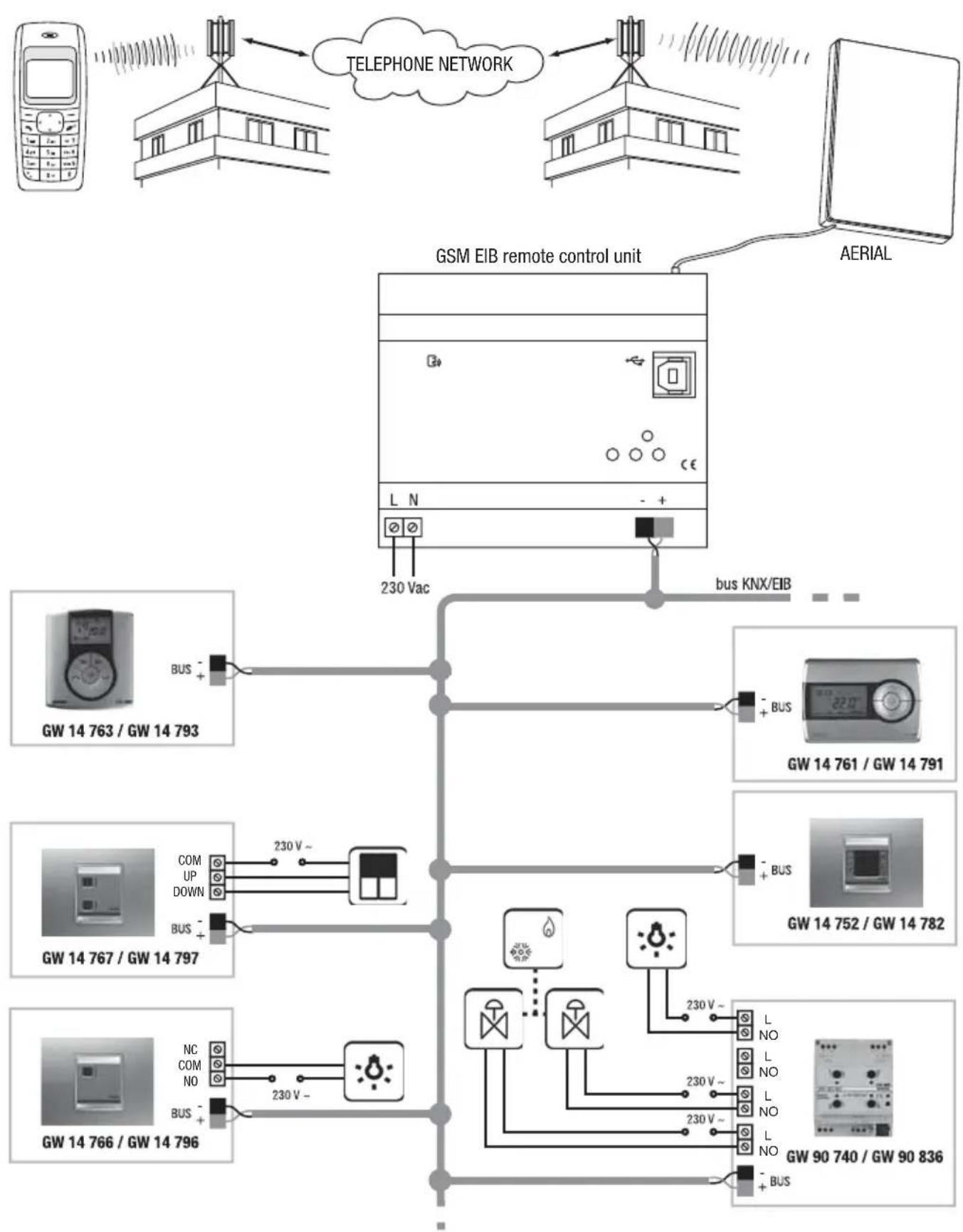
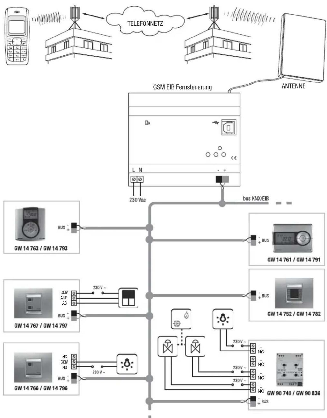
The GSM remote control unit - DIN rail provides actuator control and requests the status of controlled devices or input devices connected to the Building Automation KNX/EIB systems directly from a cellular phone via SMS messages.
Therefore, device on and off commands can be sent to the remote control unit via the GSM network to control electrical loads (for example, lamps, shutter motors, dimmers) or commands can be sent to control thermal regulation. When each command is run, the remote control unit sends a confirmation SMS to the telephone number set in the configuration phase.
Similarly, the remote control unit can autonomously send messages in case of an event.
The remote control unit is fitted with a rechargeable back-up battery to power it when the network power is down: thus, blackouts are always signalled.
The remote control unit is fitted on a 35 mm DIN rail, inside electric panels or junction boxes.
① 230 Vac power supply
② Bus terminals
③ Physical address programming LED
④ Device status indicator LED
⑤ Multi-function GSM module status indicator LED
⑥ Physical address programming button
⑦ USB Port (type B)
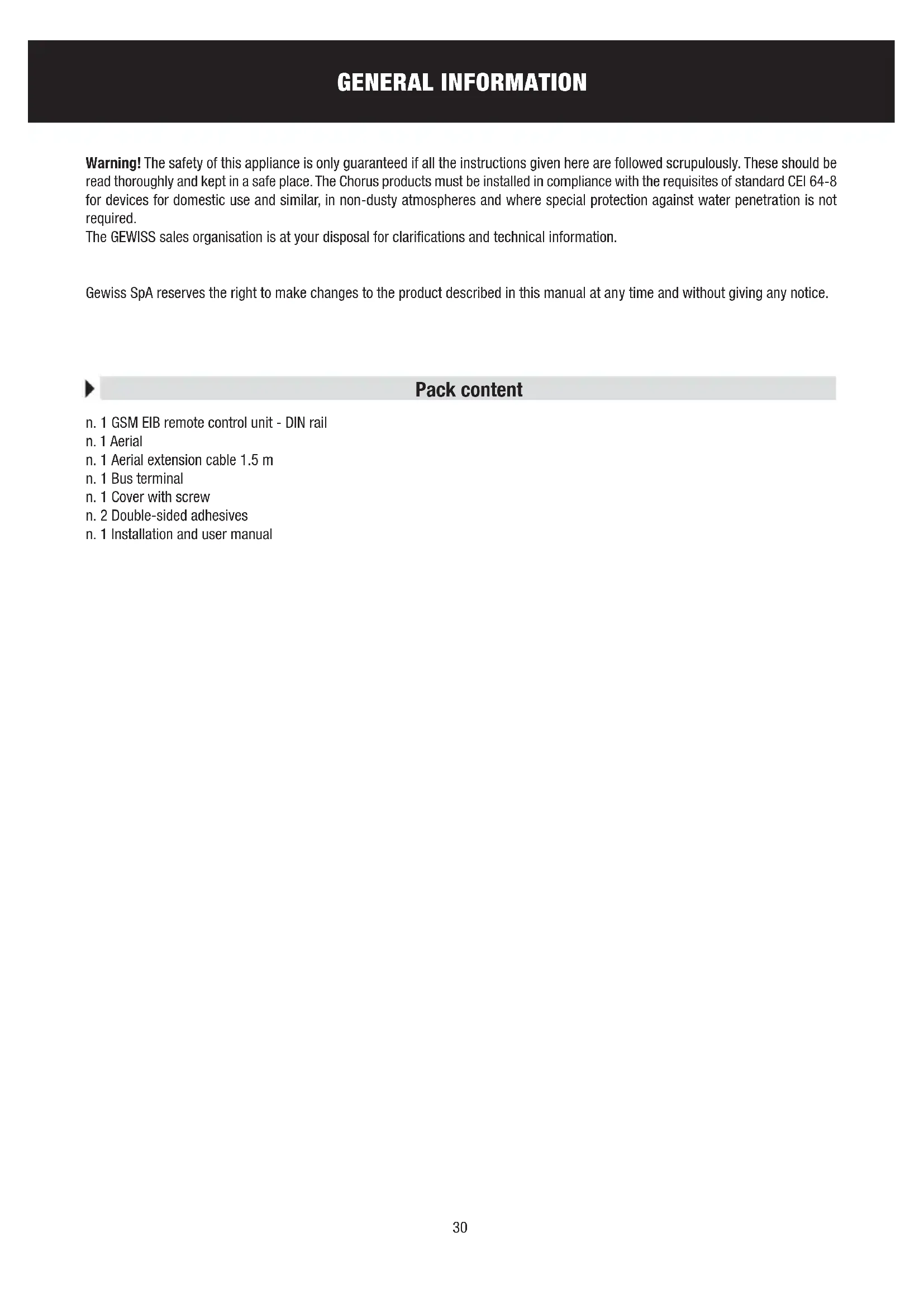
⑧ External aerial connection
⑨ SIM card slot
Functions
The device is configured by the ETS software to perform one of the functions listed below:
8 generic output command
Each output can be set to:
- send ON/OFF commands (to actuators or dimmer)
- send awning/shutter movement commands (UP/DOWN)
- send priority controls
- send scene activation and learning commands
The first 5 outputs can be set, in order, to send the following commands to the burglar alarm system (through GW 20 476 interface)
• total arming/disarming
- partial arming 1
- partial arming 2
- alarm status request
- arming enable request
GENERAL DESCRIPTION
Send 8 bit values
4 8 bit output communication objects are available. A pair of values to be transmitted to the bus can be set for each object in the following formats:
- unsigned [0..255]
- signed [-128.. +127]
• percentage value [0%.. 100%].
Send 16 bit values
2 16 bit output communication objects are available. A pair of values to be transmitted to the bus can be set for each object in the following formats:
- unsigned [0 .. 65535]
- signed [-32768.. +32767]
- floating point with set values in the interval [-100 .. +100].
1 bit input management
16 1 bit (ON/OFF) input communication objects are available and can be linked to:
- sending of SMS on receiving ON
- sending of SMS on receiving OFF
- sending of SMS on receiving ON and OFF
- sending of SMS only on request.
8 bit input management
4 8 bit input communication objects are available in formats:
- unsigned [0..255]
- signed [-128.. +127]
• percentage value [0%.. 100%].
Each object can be linked to:
- sending of SMS on receiving a value
- sending of SMS only on request.
16 bit input management
2 16 bit input communication objects are available in formats:
- unsigned [0 .. 65535]
• signed [-32768.. +32767] - floating point.
Each object can be linked to:
- sending of SMS on receiving a value
- sending of SMS only on request.
Thermal regulation
Via SMS it is possible:
• to set and request thermal regulation system operating mode (Auto/Eco/Precomfort/Comfort/OFF) and type (Heating/Conditioning).
- request the temperature read by a timed-thermostat/thermostat;
- set temperature set points.
MESSAGES SENT BY THE REMOTE CONTROL UNIT
The remote control unit sends - following a direct request, in response to an order received or as indication of an event in progress - the messages below:
| Send to calling number | Send to default number | Default text | Customised text | |
| Confirmation of execution of a command after sending a request | ||||
| ON/OFF command of a generic actuator | ■ | ▲ | ■ | |
| Shutter/blind command | ■▲■ | |||
| Dimmer ON / OFF command | ■▲■ | |||
| Priority control on/off command | ■▲■ | |||
| Scene on/learning command | ■▲■ | |||
| Setting of thermal regulation function type | ■▲■ | |||
| Setting the thermal regulation operation mode | ■▲■ | |||
| Setting the thermal regulation set point | ■▲■ | |||
| Burglar alarm system arming (total or partial) and disarming | ■ | ■ | ||
| Status signals sent automatically | ||||
| Change in input status | ■ | ■ | ||
| Burglar system alarm indicator | ■ | ■ | ||
| Status indicator in response to a request | ||||
| Status request for all managed devices | ■▲■ | |||
| Status request for all I/O | ■▲■ | |||
| Status request for timed-thermostats or thermostat (1) | ■▲■ | |||
| Status request for burglar alarm system (2) | ■▲■ | |||
▲ The reply is sent to the default telephone number if the calling number is hidden.
(1) The reply includes the current function type and mode and the room temperature
(2) The reply includes system status (on/off), unit status (ready/not ready for arming) and burglar alarm status (ON/OFF).
The SMS that confirm that a command has been executed and indicate the status of devices, and are sent by the remote control unit after receiving a request, are sent to the calling number, none excluded (upon entering the password). The only exception is the burglar alarm arming (partial or total) or disarming commands, which must be sent by a telephone number memorised in the SIM as the default number for controlling the burglar alarm system.
The status indicator SMS sent autonomously by the remote control unit are sent to the numbers indicated during the setup procedure or, if not specified, to the default telephone number. An exception to the case is the burglar alarm signal which is sent to the telephone numbers memorised in the SIM as the default numbers for burglar alarm system control.

WARNING: the installation of the device must be exclusively done by qualified personnel, following the regulations in force and the guidelines for KNX/EIB installations.
Warnings for KNX/EIB installations
- The length of the bus line between the EIB remote control unit and the power supply unit must not exceed 350 metres.
- The length of the bus line between the EIB remote control unit and the most distant KNX/EIB device must not exceed 700 metres.
- If possible do not create ring circuits so as to prevent undesirable signals and overloads.
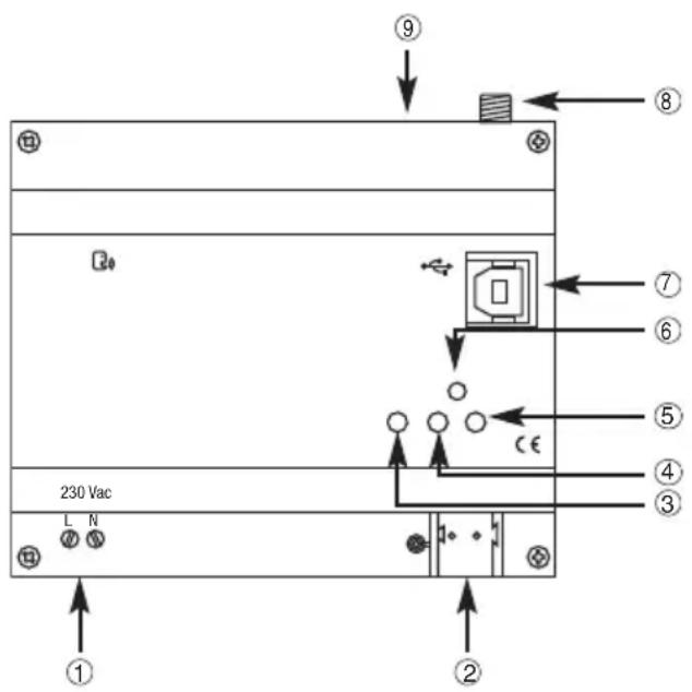
- Keep a distance of at least 4 mm between the individually insulated cables of the bus line and those of the electric line.
- Do not damage the electrical continuity conductor of the shielding.
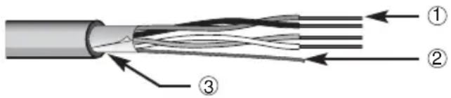
① Bus cable
② Electrical continuity conductor
③ Shield

WARNING: the unused bus signal cables and the electric continuity cable must never touch powered elements or the grounding cable!
Warnings for installation phase
The remote control unit uses wireless connections for remote connection via GSM network. It is therefore essential to adopt a series of precautions:
- position the remote control unit aerial as far as possible from all sources of electromagnetic disturbances, such as electrical motors, electricity meters, dimmers, fluorescent lights;
- NEVER install the remote control unit aerial inside control panels or metal cabinets;
- DO NOT position the remote control unit aerial in front of or behind metallic panels;
It is recommended to install a short-circuit protection device upstream of the remote control unit (for instance a magnetothermal switch) which can be useful for sectioning the line during maintenance or modifications to the remote control unit connections.
Verification of GSM signal cover
The remote control unit works with all GSM mobile phone providers. It is necessary however that the GSM network provider covers the selected installation zone and that the GSM signal is sufficiently strong. To check the signal, use a cell phone with a SIM card connected to the provider from the exact position you intend to install the units. If the signal is weak or not available, proceed as follows:
- Try another position, until you find an acceptable signal level.
- Try repositioning the aerial or replacing it with a compatible type (see the Positioning and connecting the aerial paragraph).
- Try using a SIM card connected to a different provided (the GSM cover varies from provider to provider).
It is possible to check if the signal level is acceptable using the multifunction GSM module status indicator LED: fixed green light indicates good level, red indicates no GSM signal.

WARNING: if there is no GSM signal the device cannot receive or send SMS.
SIM
The remote control accepts both SIM contract cards and prepaid SIM cards. If you use a prepaid SIM card, you have to bear in mind some aspects which could compromise standard operations.
- Recharging the SIM: when the prepaid SIM card runs out, the remote control unit can no longer send messages. The remote control unit does not send a "SIM credit finished" notice, therefore you have to remember to check that there is always sufficient credit to allow for remote communications.
- SIM expiry dates: most mobile phone providers deactivate prepaid SIM cards 11/12 months from when they were last recharged, whatever the residual credit. This problem can be overcome by enabling the automatic SIM card recharge service which most mobile phone providers supply.
- Unlocking SIM cards: if you use a new SIM card you may have to make a phone call to unlock it. To do this you have to place the SIM card in a normal cell phone and make the phone call.
- Disabling the PIN code option: it is essential to disable the GSM PIN code request option on the SIM card before installing it in the remote control unit. To do this you have to place the SIM card in a normal cell phone and follow the instructions supplied with the cell phone.
It is recommended to test that the basic functions work, such as sending an SMS, to check that all the SIM settings (SMS centre number, etc.) are all correct.
Assembly on the DIN Rial
INSERTING THE BATTERIES
Before fitting the remote control unit on the DIN gial, insert the back-up rechargeable batteries as follows:
- Unscrew the four screws on the front of the remote control unit and press the top and bottom notches together to release the cover.
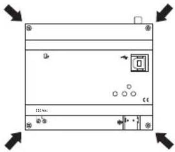
natural_image
Pure technical diagram of a rectangular device with mounting holes and internal components, no text or symbols present.- Insert 3 NiMh - AAA rechargeable batteries, making sure the poles are in the right direction. It is recommended to use batteries which are 800 mAh or higher.
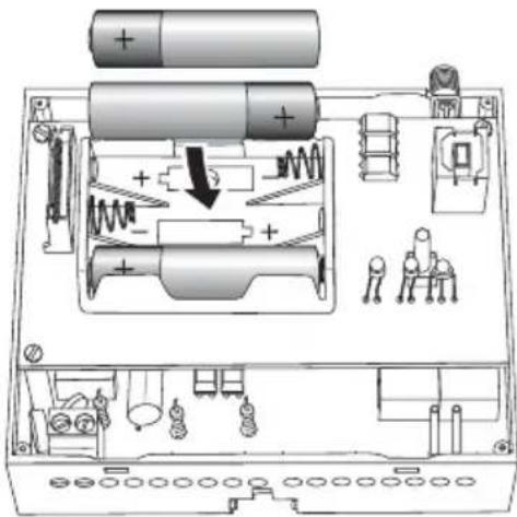
- Replace the cover on the remote control unit and fix it in place with the screws.
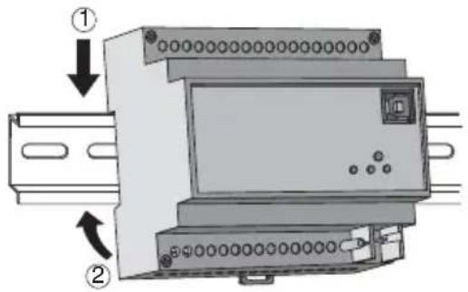
ASSEMBLY ON THE DIN RIAL
Assemble the remote control unit onto the 35 mm DIN rail as follows:
- Insert the device's upper coupling in the DIN rail.
- Rotate the device until a "click" is heard, signalling locking to the DIN rail.
Electrical connections
WARNING: disconnect the network voltage before connecting the device to the power network!
For electrical connection diagrams, see the following examples.
- Connect the bus cable's red wire to the terminal's red connector (+) and the black wire to the black connector (-). Up to 4 bus lines (wires of the same colour in the same connector) can be connected to the bus terminal.
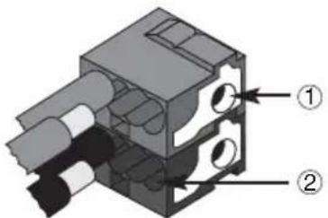
① Bus device connection
② Bus cable connection
- Insulate the screen, the electrical continuity conductor and the remaining white and yellow wires of the bus cable (should a bus cable with 4 conductors be used), which are not needed.
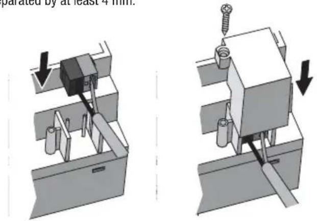
- Insert the bus connector into the special feet of the device. The fastener guides determine the direction it should be inserted. Insulate the bus terminal using the relative cover, which must be screwed onto the device. The cover guarantees that the power cables and the bus cables are separated by at least 4 mm.
Connection examples
BUILDING AUTOMATION SYSTEM
flowchart
graph TD
    A["Mobile Phone"] -->|230 V~| B["GSM EIB remote control unit"]
    B --> C["Aerial"]
    B --> D["Aerial"]
    B --> E["230 Vac"]
    B --> F["bus KNX/EIB"]
    F --> G["BUS"]
    F --> H["+ BUS"]
    F --> I["230 V~"]
    F --> J["COM UP DOWN"]
    F --> K["COM UP UP DOWN"]
    F --> L["COM UP UP DOWN"]
    F --> M["COM UP UP DOWN"]
    F --> N["COM UP UP DOWN"]
    F --> O["COM UP UP DOWN"]
    F --> P["COM UP UP DOWN"]
    F --> Q["COM UP UP DOWN"]
    F --> R["COM UP UP DOWN"]
    F --> S["COM UP UP DOWN"]
    F --> T["COM UP UP DOWN"]
    F --> U["COM UP UP DOWN"]
    F --> V["COM UP UP DOWN"]
    F --> W["COM UP UP DOWN"]
    F --> X["COM UP UP DOWN"]
    F --> Y["COM UP UP DOWN"]
    F --> Z["COM UP UP DOWN"]
    F --> AA["COM UP UP DOWN"]
    F --> AB["COM UP UP DOWN"]
    F --> AC["COM UP UP DOWN"]
    F --> AD["COM UP UP DOWN"]
    F --> AE["COM UP UP DOWN"]
    F --> AF["COM UP UP DOWN"]
    F --> AG["COM UP UP DOWN"]
    F --> AH["COM UP UP DOWN"]
    F --> AI["COM UP UP DOWN"]
    F --> AJ["COM UP UP DOWN"]
    F --> AK["COM UP UP DOWN"]
    F --> AL["COM UP UP DOWN"]
    F --> AM["COM UP UP DOWN"]
    F --> AN["COM UP UP DOWN"]
    F --> AO["COM UP UP DOWN"]
    F --> AP["COM UP UP DOWN"]
    F --> AQ["COM UP UP DOWN"]
    F --> AR["COM UP UP DOWN"]
    F --> AS["COM UP UP DOWN"]
    F --> AT["COM UP UP DOWN"]
    F --> AU["COM UP UP DOWN"]
    F --> AV["COM UP UP DOWN"]
    F --> AW["COM UP UP DOWN"]
    F --> AX["COM UP UP DOWN"]
    F --> AY["COM UP UP DOWN"]
    F --> AZ["COM UP UP DOWN"]
    F --> BA["COM UP UP DOWN"]
    F --> BB["COM UP UP DOWN"]
    F --> BC["COM UP UP DOWN"]
    F --> BD["COM UP UP DOWN"]
    F --> BE["COM UP UP DOWN"]
    F --> BF["COM UP UP DOWN"]
    F --> BG["COM UP UP DOWN"]
    F --> BH["COM UP UP DOWN"]
    F --> BI["COM UP UP DOWN"]
    F --> BJ["COM UP UP DOWN"]
    F --> BK["COM UP UP DOWN"]
    F --> BL["COM UP UP DOWN"]
    F --> BM["COM UP UP DOWN"]
    F --> BN["COM UP UP DOWN"]
    F --> BO["COM UP UP DOWN"]
    F --> BP["COM UP UP DOWN"]
    F --> BQ["COM UP UP DOWN"]
    F --> BR["COM UP UP DOWN"]
    F --> BS["COM UP UP DOWN"]
    F --> BT["COM UP UP DOWN"]
    F --> BU["COM UP UP DOWN"]
    F --> BV["COM UP UP DOWN"]
    F --> BW["COM UP UP DOWN"]
    F --> BX["COM UP UP DOWN"]
    F --> BY["COM UP UP DOWN"]
    F --> BZ["COM UP UP DOWN"]
    F --> CA["COM UP UP DOWN"]
INSTALLATION
SIM insertion
To insert the SIM card inside the remote control unit:
- Use a biro or pencil to press the little yellow release button to the side of the SIM card slot.
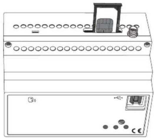
- Open the SIM card slot.
- Insert the SIM card in the slot making sure the rounded edge faces the top right corner and the gold contacts are visible.
- Close the SIM card slot.
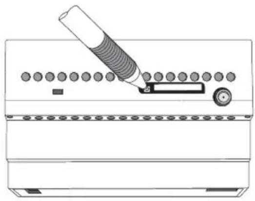
natural_image
Diagram of a mechanical device with a cylindrical tool inserted into a slot, showing no text or symbols.Releasing the SIM card slot SIM connection position
natural_image
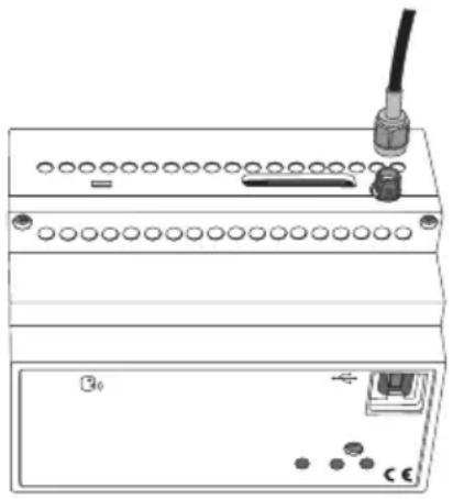
Line drawing of a dual-panel electronic device with circular ports and a door (no text or symbols)Aerial position and connection
Make sure you position the remote control unit aerial:
- as far as possible from all sources of electromagnetic disturbances, such as electrical motors, electricity meters, dimmers, fluorescent lights;
- outside electric panels or metal cabinets;
- at a distance from any metal panels;
- in a dry area (the aerial casing is not waterproof);
- in a protected place, to prevent accidental or intentional damage.
The aerial can be fixed to a wall or a smooth surface using the double-sided adhesive strips supplied with the pack.
The remote control unit is supplied with a 1.5 m aerial extension to make it easier to position the aerial. This extension should only be used if necessary.
Connect the aerial by screwing its cable onto the SMA connector situated at the top of the remote control unit. Screw it on by hand, without using any tools, to make sure you don't damage the connector.
natural_image
Diagram of a device rear panel with ports, connectors, and a cable (no text or symbols)Commissioning
After connecting the device to the power supply, the device status indicator LED will start to flash to inform you that the GSM module initialising phase is in progress.
After around 30 seconds the LED will show a fixed green light: this means that the device has been correctly initialised.
If the GSM module status indicator LED is green, it means that the GSM network is available; if it is red, this means that the GSM signal is too weak.
Physical address programming
- Power up the device using the bus.
- Press the programming button to set the remote control unit to load the physical address from ETS.
Both 230V and bus power are required to set the device via ETS.
PROGRAMMING
Configuration procedures
The remote control unit can be configured using a PC, connected to the device with a USB cable, using the configuration software, or by cell phone by sending SMS.
The first procedure is recommended the first time you install and configure the device, whilst the second procedure is particularly useful when you have to remotely configure the remote control unit.
In order for the remote control unit to work properly, you have to configure the following:
- Access password.
- Reply default telephone number.
- Telephone numbers (optional) authorised to control the burglar alarm system or modify the parameters.
- Interfaces enabling (if present).
- Inputs: enable event, message text relative to the event, telephone number for SMS sending (only if different from the default number).
- Output status notification: generic or burglar alarm use, enable event, message text relative to the event, telephone number for SMS sending (only if different from the default number).
- Outputs: confirmation message text.
Password
The password is needed by the remote control unit to identify the caller before performing the instructions received via SMS. The password consists in 4 alphanumeric characters, chosen by the user from 0...9, a...z, A...Z.
The remote control unit recognises upper case and lower case letters, therefore "ab12" is different from "AB12".
To save the password, please refer to the Basic configuration paragraph.
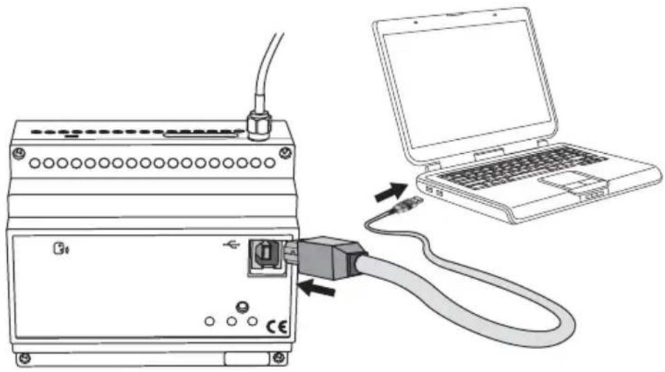
PC configuration
natural_image
Line drawing of an electronic device connected to a laptop via cable, showing ports and wiring (no text or symbols)CONNECTING THE PC TO THE REMOTE CONTROL UNIT
If you intend to configure the remote control unit using a PC, it must be connected to the power supply.
USING THE CONFIGURATION SOFTWARE
The software used to configure the device from the PC can be downloaded from our website www.gewiss.com in the GSM EIB GW 90 815 remote control unit page.
The software user manual is also available in the same section.
Interaction and configuration via SMS
The remote control unit accepts commands and queries via SMS for the devices or systems it is connected to. The commands are always received by the remote control unit after entering the password, from all incoming telephone numbers, visible or hidden. This is not the case for the configuration commands and all commands regarding the burglar alarm system, which can only be accessed from an incoming number which is visible and listed on the SIM memory as default numbers (please see the Basic Settings paragraph). These are the main rules to follow when sending SMS:
UPPER CASE AND LOWER CASE
The remote control unit recognises upper case and lower case letters in SMS (therefore a "p" is different from a "P"). All letters used in the commands and setting must be in lower case.
STRUCTURE OF THE SMS SENT
The SMS must start with a full stop (".") followed by the password (see the Password paragraph), another full stop, the command, and another full stop. No spaces are accepted between the full stops and the password or command.
Syntax: .password.command.
Examples of correct SMS: .AB01.SGE00-0.
.AB01.P401-Stop water pump.
Examples of incorrect SMS: .AB01. SGE00-0.
.AB01.SGE00-0.
MULTIPLE COMMANDS
One SMS can be used to send multiple commands separated by a full stop ("."). The SMS must not exceed 480 characters.
Syntax: .password.command1.command2.command3.command4.
E.g.: .AB01.COE01-1.COE06-3.CCE01-1.
CUSTOMISED TEXTS
The customised text or the reply messages cannot exceed 20 characters, spaces included, and must not contain full stops (""."). Other punctuation marks are allowed.
Example of a correct text message: Timed-thermostat seaside
Examples of incorrect text message: Timed-thermostat seaside villa (text too long), Timed-therm. seaside villa (full stop in the text)
TELEPHONE NUMBERS
WARNING: All telephone numbers must be keyed in without spaces or hyphens. The international prefix for the number must be entered using the +prefix format (for Italy +39).
The telephone that corresponds to the number must be able to receive SMS.
The numbers memorised in the remote control unit memory to which the SMS must be sent, must be in the international format of the Country where the remote control unit is installed.
The remote control unit only recognises the number sending the SMS if it is in the same format as the number memorised on the SIM card.
Examples of incorrect numbers: +39 035 94611 (spaces), 338-55523 (hyphen and no international prefix)
Examples of correct numbers: +3903594611, +3933855523
The remote control unit applies the following rules when sending SMS:
- The replies to commands or status queries are sent to the incoming number, if visible, or to the default number (see Basic Settings) if it is hidden.
- The SMS sent autonomously by the remote control unit, for instance the alarms and the input switchings, are sent to the number keyed in for this specific event or, if absent, to the default number.
PROGRAMMING
Basic configuration
For security reasons, some of the settings cannot be made via SMS but must be made using a cell phone directly on the SIM card to be installed on the remote control unit or programmed using the software.
To set these parameters from a cell phone, please proceed as follows:
- Insert the SIM you will be using for the remote control unit into your cell phone. Follow the instructions provided in the cell phone manual for this operation.
- Use the cell phone display and keys to save the parameters seen in the chart below onto the SIM card
| Position SIM memory | Description | Contact name on the SIM | Contact number on the SIM (1) |
| 1 Password (4 alphanumerical characters) Password (2) | |||
| 2 Default reply number (2) n. telephone | |||
| 3 | Number 1 to control the burglar alarm system and modify settings via SMS | (2) | n. telephone |
| 4 | Number 2 to control the burglar alarm system and modify settings via SMS | (2) | n. telephone |
| 5 | Number 3 to control the burglar alarm system and modify settings via SMS | (2) | n. telephone |
| 6 | Number 4 to control the burglar alarm system and modify settings via SMS | (2) | n. telephone |
| 7 | Number 5 to control the burglar alarm system and modify settings via SMS | (2) | n. telephone |
(1) For further information on the telephone number format on the SIM card, please refer to the Telephone number paragraph.
(2) Leave the field empty.
The alarm messages will be sent to all the numbers indicated under the burglar alarm system section.
To save the information on the SIM card, please proceed as follows:
a) select the memory position as required;
b) leave the "contact name" field empty, except if a password is required; in this case enter the chosen password;
c) key in the telephone number in the "contact number" field (the password does not require a phone number; any phone numbers will be ignored).
Before proceeding and saving the numbers and the password on the SIM, it is recommended to cancel all the contacts already saved on the card, to make sure that the entered numbers are saved in the listed memory fields.
Before changing the telephone numbers or the password saved on the SIM card, it is necessary to disconnect the remote control unit from the power supply, so that when you power it up again it will receive the new numbers saved.
- Remove the SIM card from the cell phone and replace it in the remote control unit as explained in the Inserting the SIM card paragraph.
WARNING: If the configuration is done using the software, the data will automatically be stored in the positions listed in the chart, overwriting any information already saved on the SIM card.
Configuration via SMS
The parameters below must be configured via SMS. The SMS is only accepted if it is sent from a visible number which corresponds to one of the numbers saved to the SIM card memory authorised to configure parameters.
GENERAL CONFIGURATION
| Command Description | |
| P200-1 Send copy of messages also to the default phone number | |
| P200-0 Do not send copy of messages also to the default phone number | |
| P201-1 Not used | |
| P201-0 Not used | |
| P204-text Output command confirmation text | |
| P205-text Blackout warning text | |
| P206-text Power reinstatement warning text | |
| P207-text Battery replacement request text | |
NOTE: The character in the charts represents the number zero.
1-BIT KNX INPUT CONFIGURATION
| Command Description | |
| P400-0 Input 1: SMS send condition: reception "ON" | |
| P400-1 Input 1: SMS send condition: reception "OFF" | |
| P400-2 Input 1: SMS send condition: reception "ON" and "OFF" | |
| P400-3 Input 1: send SMS only on request | |
| P401-text Input 1: SMS message text for reception "ON" | |
| P402-text Input 1: SMS message text for reception "OFF" | |
| P403-telephone number Input 1: telephone number for SMS sending | |
| P405-0 Input 2: sending of SMS on receiving "ON" | |
| P405-1 Input 2: SMS send condition: reception "OFF" | |
| P405-2 Input 2: SMS send condition: reception "ON" and "OFF" | |
| P405-3 Input 2: send SMS only on request | |
| P406-text Input 2: SMS message text for reception "ON" | |
| P407-text Input 2: SMS message text for reception "OFF" | |
| P408-telephone number Input 2: telephone number for SMS sending | |
| P410-0 Input 3: SMS send condition: reception "ON" | |
| P410-1 Input 3: SMS send condition: reception "OFF" | |
| P410-2 Input 3: SMS send condition: reception "ON" and "OFF" | |
| P410-3 Input 3: send SMS only on request | |
| P411-text Input 3: SMS message text for reception "ON" | |
| P412-text Input 3: SMS message text for reception "OFF" | |
| P413-telephone number Input 3: telephone number for SMS sending | |
| P415-0 Input 4: SMS send condition: reception "ON" | |
| P415-1 Input 4: SMS send condition: reception "OFF" | |
| P415-2 Input 4: SMS send condition: reception "ON" and "OFF" | |
| P415-3 Input 4: send SMS only on request | |
| P416-text Input 4: SMS message text for reception "ON" | |
| P417-text Input 4: SMS message text for reception "OFF" | |
| P418-telephone number Input 4: telephone number for SMS sending | |
| P420-0 Input 5: SMS send condition: reception "ON" | |
| P420-1 Input 5: SMS send condition: reception "OFF" | |
| P420-2 Input 5: SMS send condition: reception "ON" and "OFF" | |
| P420-3 Input 5: send SMS only on request | |
| P421-text Input 5: SMS message text for reception "ON" | |
| P422-text Input 5: SMS message text for reception "OFF" | |
| P423-telephone number Input 5: telephone number for SMS sending | |
| P425-0 Input 6: SMS send condition: reception "ON" | |
| P425-1 Input 6: SMS send condition: reception "OFF" | |
| P425-2 Input 6: SMS send condition: reception "ON" and "OFF" | |
| P425-3 Input 6: send SMS only on request | |
| P426-text Input 6: SMS message text for reception "ON" | |
| P427-text Input 6: SMS message text for reception "OFF" | |
| P428-telephone number Input 6: telephone number for SMS sending | |
| P430-0 Input 7: SMS send condition: reception "ON" | |
| P430-1 Input 7: SMS send condition: reception "OFF" | |
| P430-2 Input 7: SMS send condition: reception "ON" and "OFF" | |
| P430-3 Input 7: send SMS only on request | |
| P431-text Input 7: SMS message text for reception "ON" | |
| P432-text Input 7: SMS message text for reception "OFF" | |
| P433-telephone number Input 7: telephone number for SMS sending | |
NOTE: The character in the charts represents the number zero.
| Command Description | |
| P435-0 Input 8: SMS send condition: reception "ON" | |
| P435-1 Input 8: SMS send condition: reception "OFF" | |
| P435-2 Input 8: SMS send condition: reception "ON" and "OFF" | |
| P435-3 Input 8: send SMS only on request | |
| P436-text Input 8: SMS message text for reception "ON" | |
| P437-text Input 8: SMS message text for reception "OFF" | |
| P438-telephone number Input 8: telephone number for SMS sending | |
| P440-0 Input 9: SMS send condition: reception "ON" | |
| P440-1 Input 9: SMS send condition: reception "OFF" | |
| P440-2 Input 9: SMS send condition: reception "ON" and "OFF" | |
| P440-3 Input 9: send SMS only on request | |
| P441-text Input 9: SMS message text for reception "ON" | |
| P442-text Input 9: SMS message text for reception "OFF" | |
| P443-telephone number Input 9: telephone number for SMS sending | |
| P445-0 Input 10: SMS send condition: reception "ON" | |
| P445-1 Input 10: SMS send condition: reception "OFF" | |
| P445-2 Input 10: SMS send condition: reception "ON" and "OFF" | |
| P445-3 Input 10: send SMS only on request | |
| P446-text Input 10: SMS message text for reception "ON" | |
| P447-text Input 10: SMS message text for reception "OFF" | |
| P448-telephone number Input 10: telephone number for SMS sending | |
| P450-0 Input 11: SMS send condition: reception "ON" | |
| P450-1 Input 11: SMS send condition: reception "OFF" | |
| P450-2 Input 11: SMS send condition: reception "ON" and "OFF" | |
| P450-3 Input 11: send SMS only on request | |
| P451-text Input 11: SMS message text for reception "ON" | |
| P452-text Input 11: SMS message text for reception "OFF" | |
| P453-telephone number Input 11: telephone number for SMS sending | |
| P455-0 Input 12: SMS send condition: reception "ON" | |
| P455-1 Input 12: SMS send condition: reception "OFF" | |
| P455-2 Input 12: SMS send condition: reception "ON" and "OFF" | |
| P455-3 Input 12: send SMS only on request | |
| P456-text Input 12: SMS message text for reception "ON" | |
| P457-text Input 12: SMS message text for reception "OFF" | |
| P458-telephone number Input 12: telephone number for SMS sending | |
| P460-0 Input 13: SMS send condition: reception "ON" | |
| P460-1 Input 13: SMS send condition: reception "OFF" | |
| P460-2 Input 13: SMS send condition: reception "ON" and "OFF" | |
| P460-3 Input 13: send SMS only on request | |
| P461-text Input 13: SMS message text for reception "ON" | |
| P462-text Input 13: SMS message text for reception "OFF" | |
| P463-telephone number Input 13: telephone number for SMS sending | |
| P465-0 Input 14: SMS send condition: reception "ON" | |
| P465-1 Input 14: SMS send condition: reception "OFF" | |
| P465-2 Input 14: SMS send condition: reception "ON" and "OFF" | |
| P465-3 Input 14: send SMS only on request | |
| P466-text Input 14: SMS message text for reception "ON" | |
| P467-text Input 14: SMS message text for reception "OFF" | |
| P468-telephone number Input 14: telephone number for SMS sending | |
NOTE: The character in the charts represents the number zero.
PROGRAMMING
| Command Description | |
| P470-0 Input 15: SMS send condition: reception "ON" | |
| P470-1 Input 15: SMS send condition: reception "OFF" | |
| P470-2 Input 15: SMS send condition: reception "ON" and "OFF" | |
| P470-3 Input 15: send SMS only on request | |
| P471-text Input 15: SMS message text for reception "ON" | |
| P472-text Input 15: SMS message text for reception "OFF" | |
| P473-telephone number Input 15: telephone number for SMS sending | |
| P475-0 Input 16: SMS send condition: reception "ON" | |
| P475-1 Input 16: SMS send condition: reception "OFF" | |
| P475-2 Input 16: SMS send condition: reception "ON" and "OFF" | |
| P475-3 Input 16: send SMS only on request | |
| P476-text Input 16: SMS message text for reception "ON" | |
| P477-text Input 16: SMS message text for reception "OFF" | |
| P478-telephone number Input 16: telephone number for SMS sending | |
NOTE: The character in the charts represents the number zero.
8-BIT KNX INPUT CONFIGURATION
| Command Description | |
| P480-∅ Input 1: SMS send condition: reception value | |
| P480-3 Input 1: send SMS only on request | |
| P481-text Input 1: SMS message text for reception value | |
| P483-telephone number Input 1: telephone number for SMS sending | |
| P485-∅ Input 2: SMS send condition: reception value | |
| P485-3 Input 2: send SMS only on request | |
| P486-text Input 2: SMS message text for reception value | |
| P488-telephone number Input 2: telephone number for SMS sending | |
| P490-∅ Input 3: SMS send condition: reception value | |
| P490-3 Input 3: send SMS only on request | |
| P491-text Input 3: SMS message text for reception value | |
| P493-telephone number Input 3: telephone number for SMS sending | |
| P495-∅ Input 4: SMS send condition: reception value | |
| P495-3 Input 4: send SMS only on request | |
| P496-text Input 4: SMS message text for reception value | |
| P498-telephone number Input 4: telephone number for SMS sending | |
NOTE: The character in the charts represents the number zero.
16-BIT KNX INPUT CONFIGURATION
| Command Description | |
| P500-0 Input 1: SMS send condition: reception value | |
| P500-3 Input 1: send SMS only on request | |
| P501-text Input 1: SMS message text for reception value | |
| P503-telephone number input 1: telephone number for SMS sending | |
| P505-0 Input 2: SMS send condition: reception value | |
| P505-3 Input 2: send SMS only on request | |
| P506-text Input 2: SMS message text for reception value | |
| P508-telephone number input 2: telephone number for SMS sending | |
NOTE: The character in the charts represents the number zero.
PROGRAMMING
CONFIGURATION OF KNX OUTPUTS
The "command sent confirmation" message is made up of the KNK output configuration text field plus the output command confirmation text general configuration text field.
E.g.: with default values, the message is made up as follows: OUT_KNK_1=DONE
| Command Description | |
| P600-text | Generic output 1 command sent confirmation SMS message text |
| P605-text | Generic output 2 command sent confirmation SMS message text |
| P610-text | Generic output 3 command sent confirmation SMS message text |
| P615-text | Generic output 4 command sent confirmation SMS message text |
| P620-text | Generic output 5 command sent confirmation SMS message text |
| P625-text | Generic output 6 command sent confirmation SMS message text |
| P630-text | Generic output 7 command sent confirmation SMS message text |
| P635-text | Generic output 8 command sent confirmation SMS message text |
| P640-text 8 bit object 1 sent confirmation SMS message text | |
| P645-text 8 bit object 2 sent confirmation SMS message text | |
| P650-text 8 bit object 3 sent confirmation SMS message text | |
| P655-text 8 bit object 4 sent confirmation SMS message text | |
| P660-text 16 bit object 1 sent confirmation SMS message text | |
| P665-text 16 bit object 2 sent confirmation SMS message text | |
NOTE: The character in the charts represents the number zero.
CONFIGURATION OF KNX THERMAL REGULATION
| Command Description | |
| P730-text Connected KNX | EIB thermal regulation device name |
NOTE: The character in the charts represents the number zero.
CONFIGURATION REQUEST
| Command Description | |
| R200 Send SMS with general settings | |
| R220 Not used | |
| R400 Send SMS with 1 bit KNX input settings (from 1 to 4) | |
| R420 Send SMS with 1 bit KNX input settings (from 5 to 8) | |
| R440 Send SMS with 1 bit KNX input settings (from 9 to 12) | |
| R460 Send SMS with 1 bit KNX input settings (from 13 to 16) | |
| R480 Send SMS with 8 bit KNX input settings | |
| R500 Send SMS with 16 bit KNX input settings | |
| R600 Send SMS with settings for KNX outputs | |
| R700 Send SMS with thermal regulation settings | |
NOTE: The character in the charts represents the number zero.
Final Inspection
After completing the installation and configuration of the remote control unit, try the main functions to check that the remote control unit works properly.
Remote control via SMS
The commands to remotely interact with the various inputs, outputs and systems via SMS are listed in the charts below.
The command sent to the bus when the SMS is received depends on output channel ETS configuration as described in the Functions paragraph.
GENERIC OUTPUT COMMANDS
| Command Description |
| COE01-1 Output 1: ON/Override on/Scene B on/Shutter DOWN |
| COE01-0 Output 1: OFF/Override off/Scene A on/Shutter UP |
| COE01-2 Output 1: Learning scene A |
| COE01-3 Output 1: Learning scene B |
| COE02-1 Output 2: ON/Override on/Scene B on/Shutter DOWN |
| COE02-0 Output 2: OFF/Override off/Scene A on/Shutter UP |
| COE02-2 Output 2: Learning scene A |
| COE02-3 Output 2: Learning scene B |
| COE03-1 Output 3: ON/Override on/Scene B on/Shutter DOWN |
| COE03-0 Output 3: OFF/Override off/Scene A on/Shutter UP |
| COE03-2 Output 3: Learning scene A |
| COE03-3 Output 3: Learning scene B |
| COE04-1 Output 4: ON/Override on/Scene B on/Shutter DOWN |
| COE04-0 Output 4: OFF/Override off/Scene A on/Shutter UP |
| COE04-2 Output 4: Learning scene A |
| COE04-3 Output 4: Learning scene B |
| COE05-1 Output 5: ON/Override on/Scene B on/Shutter DOWN |
| COE05-0 Output 5: OFF/Override off/Scene A on/Shutter UP |
| COE05-2 Output 5: Learning scene A |
| COE05-3 Output 5: Learning scene B |
| COE06-1 Output 6: ON/Override on/Scene B on/Shutter DOWN |
| COE06-0 Output 6: OFF/Override off/Scene A on/Shutter UP |
| COE06-2 Output 6: Learning scene A |
| COE06-3 Output 6: Learning scene B |
| COE07-1 Output 7: ON/Override on/Scene B on/Shutter DOWN |
| COE07-0 Output 7: OFF/Override off/Scene A on/Shutter UP |
| COE07-2 Output 7: Learning scene A |
| COE07-3 Output 7: Learning scene B |
| COE08-1 Output 8: ON/Override on/Scene B on/Shutter DOWN |
| COE08-0 Output 8: OFF/Override off/Scene A on/Shutter UP |
| COE08-2 Output 8: Learning scene A |
| COE08-3 Output 8: Learning scene B |
NOTE: The character in the charts represents the number zero.
BURGLAR ALARM SYSTEM COMMANDS
Generic output channels 1 through 5 can be set to control the burglar alarm system. It is possible to set the following commands:
| Command Description | |
| COE01-∅ Burglar alarm system disarming | |
| COE01-1 Complete burglar alarm system arming | |
| COE02-1 Partial arming 1 of the burglar alarm system | |
| COE03-1 Partial arming 2 of the burglar alarm system | |
| COE04-∅ | Arming enable status request |
| COE04-1 | Arming enable status request |
| COE05-∅ | Alarm status request |
| COE05-1 | Alarm status request |
NOTE: The character in the charts represents the number zero.
8-BIT OUTPUT COMMANDS
| Command Description |
| CVE01-1 8 bit object 1: send value 1 |
| CVE01-2 8 bit object 1: send value 2 |
| CVE02-1 8 bit object 2: send value 1 |
| CVE02-2 8 bit object 2: send value 2 |
| CVE03-1 8 bit object 3: send value 1 |
| CVE03-2 8 bit object 3: send value 2 |
| CVE04-1 8 bit object 4: send value 1 |
| CVE04-2 8 bit object 4: send value 2 |
NOTE: The character in the charts represents the number zero.
16-BIT OUTPUT COMMANDS
| Command Description | |
| CVE05-1 16 bit | object 1: send value 1 |
| CVE05-2 16 bit | object 1: send value 2 |
| CVE06-1 16 bit | object 2: send value 1 |
| CVE06-2 16 bit | object 2: send value 2 |
NOTE: The character in the charts represents the number zero.
KNX TIMED-THERMOSTAT OR THERMOSTAT COMMANDS
| Command Description | |
| CCE01-H Sets the function type: HEATING | |
| CCE01-C Sets the function type: CONDITIONING | |
| CCE01-0 Sets OFF mode | |
| CCE01-1 Sets ECONOMY mode | |
| CCE01-2 Sets PRECOMFORT mode | |
| CCE01-3 Sets COMFORT mode | |
| CCE01-A | Sets AUTO mode |
| CCE02-0 | Sets antifreeze set point |
| CCE02-1 | Sets ECONOMY set point (heating) |
| CCE02-2 | Sets PRECOMFORT set point (heating) |
| CCE02-3 | Sets COMFORT set point (heating) |
| CCE03-0 | Sets high temperature protection set point |
| CCE03-1 | Sets ECONOMY set point (conditioning) |
| CCE03-2 | Sets PRECOMFORT set point (conditioning) |
| CCE03-3 | Sets COMFORT set point (conditioning) |
NOTE: The character in the charts represents the number zero.
The temperature value is set using a comma as a decimal point, for example, 21,5 or 18,2.
STATUS REQUEST COMMANDS
| Command Description | |
| SGE00-0 Status request for all managed KNX inputs and devices | |
| SGE00-1 Status request for KNX inputs | |
| SGE00-2 Device status request for thermal regulation | |
| SGE00-3 Status request for burglar alarm system | |
NOTE: The character in the charts represents the number zero.
Local indications
On the front of the remote control unit there are 2 LEDs which indicate the function status of the device and 1 red programming LED.
Device status green signal LED
| LED with fixed light no malfunction |
| LED flashing • device configuration in progress• malfunction (SIM not ready, SIM protected by PIN code...) |
GSM module status indicator LED
| LED on (green) GSM network present |
| LED on (red) GSM network absent |
| LED on (yellow) elaboration of incoming SMS |
Emergency blackout function
If there is a blackout the remote control unit will send an SMS to signal lack of power and send another when the power is reinstated.
Cleaning the remote control unit
Use a dry cloth if any cleaning is required.
Replacing the batteries
The back-up batteries do not need replacing. If they should be replaced, please refer to the Inserting the batteries paragraph. The new ones must be NiMh - AAA rechargeable batteries.

WARNING
- Only the installation technician is allowed to change the batteries after disconnecting the remote control unit from the power supply.
When the power supply is disconnected this will also cancel the "CHANGE BATTERIES" warning - Replace all three batteries at the same time.
- Never use old and new batteries together.
- Always use the same type of batteries (do not mix different sized batteries).
- Never throw the batteries into a fire.
- The batteries are a special waste product and therefore it must be disposed of according to the laws in force and taken to a special collection centre.

Recharging the SIM
If you use a prepaid SIM card you have to make sure it always has enough credit for the remote control unit to be able to send and receive alarm messages.
Please contact your cell phone provider regarding the recharging procedure, residual credit information and the automatic recharging service that many providers offer.
TECHNICAL DATA
Remote communication Through the GSM network
Communication elements 1 quad-band GSM module
Power supply 230 Vac + 3 NiMh AAA rechargeable backup batteries
(recommended capacity 800 mAh or higher)
Power consumption 2 W
Bus current consumption 1.5 mA
Control elements 1 mini physical address programming key
Display elements 1 multi-function red/green/yellow LED to indicate
GSM module status
1 green LED for device status signal
1 red physical address programming LED
Ambit of use Indoors, dry places
Operating temperature
Storage temperature
Relative humidity
PC connection
Bus connection
Electrical connections
Protection rating
Dimension
Reference standards
-5 ÷ +45 °C
-25 ÷ +70 °C
Max 93% (no condensation)
1 USB port type B
Slot in terminal, 2 pin ∅ 1 mm
Screw terminals, max cable width: 2.5 mm²
IP20
6 DIN modules
Low Voltage Directive 72/23/EC
Electromagnetic compatibility directive 89/336 EC EN50428,
EN50090
ETSI EN301 489-7, ETSI EN301 511
Default values
Enable copy message function ∅ = no device connected
NOTE: The character in the charts represents the number zero.
BASIC OPTIONS
| Output command confirmation text DONE | |
| Blackout warning text 230V POWER SUPPLY KO | |
| Power reinstatement warning text 230V POWER SUPPLY OK | |
| Battery replacement request text CHANGE BATTERIES |
SIM
| Password (4 alphanumeric characters) 0000 |
NOTE: The character in the charts represents the number zero.
1-BIT KNX INPUTS
| Input 1: SMS message text for reception "ON" INP_KNX_1=ON | |
| Input 1: SMS message text for reception "OFF" INP_KNX_1=OFF | |
| Input 2: SMS message text for reception "ON" INP_KNX_2=ON | |
| Input 2: SMS message text for reception "OFF" INP_KNX_2=OFF | |
| Input 3: SMS message text for reception "ON" INP_KNX_3=ON | |
| Input 3: SMS message text for reception "OFF" INP_KNX_3=OFF | |
| Input 4: SMS message text for reception "ON" INP_KNX_4=ON | |
| Input 4: SMS message text for reception "OFF" INP_KNX_4=OFF | |
| Input 5: SMS message text for reception "ON" INP_KNX_5=ON | |
| Input 5: SMS message text for reception "OFF" INP_KNX_5=OFF | |
| Input 6: SMS message text for reception "ON" INP_KNX_6=ON | |
| Input 6: SMS message text for reception "OFF" INP_KNX_6=OFF | |
| Input 7: SMS message text for reception "ON" INP_KNX_7=ON | |
| Input 7: SMS message text for reception "OFF" INP_KNX_7=OFF | |
| Input 8: SMS message text for reception "ON" INP_KNX_8=ON | |
| Input 8: SMS message text for reception "OFF" INP_KNX_8=OFF | |
| Input 9: SMS message text for reception "ON" INP_KNX_9=ON | |
| Input 9: SMS message text for reception "OFF" INP_KNX_9=OFF | |
| Input 10: SMS message text for reception "ON" INP_KNX_10=ON | |
| Input 10: SMS message text for reception "OFF" INP_KNX_10=OFF | |
| Input 11: SMS message text for reception "ON" INP_KNX_11=ON | |
| Input 11: SMS message text for reception "OFF" INP_KNX_11=OFF | |
| Input 12: SMS message text for reception "ON" INP_KNX_12=ON | |
| Input 12: SMS message text for reception "OFF" INP_KNX_12=OFF | |
| Input 13: SMS message text for reception "ON" INP_KNX_13=ON | |
| Input 13: SMS message text for reception "OFF" INP_KNX_13=OFF | |
| Input 14: SMS message text for reception "ON" INP_KNX_14=ON | |
| Input 14: SMS message text for reception "OFF" INP_KNX_14=OFF | |
| Input 15: SMS message text for reception "ON" INP_KNX_15=ON | |
| Input 15: SMS message text for reception "OFF" INP_KNX_15=OFF | |
| Input 16: SMS message text for reception "ON" INP_KNX_16=ON | |
| Input 16: SMS message text for reception "OFF" INP_KNX_16=OFF |
NOTE: The character in the charts represents the number zero.
8-BIT KNX INPUTS
| Input 1: SMS message text for reception value INP_VAL8_KNK_1 | |
| Input 2: SMS message text for reception value INP_VAL8_KNK_2 | |
| Input 3: SMS message text for reception value INP_VAL8_KNK_3 | |
| Input 4: SMS message text for reception value INP_VAL8_KNK_4 |
16-BIT KNX INPUTS
| Input 1: SMS message text for reception value INP_VAL16_KNK_1 | |
| Input 2: SMS message text for reception value INP_VAL16_KNK_2 |
TECHNICAL DATA
GENERIC OUTPUTS
| Output 1 command completed confirmation message text OUT_KNK_1 | |
| Output 2 command completed confirmation message text OUT_KNK_2 | |
| Output 3 command completed confirmation message text OUT_KNK_3 | |
| Output 4 command completed confirmation message text OUT_KNK_4 | |
| Output 5 command completed confirmation message text OUT_KNK_5 | |
| Output 6 command completed confirmation message text OUT_KNK_6 | |
| Output 7 command completed confirmation message text OUT_KNK_7 | |
| Output 8 command completed confirmation message text OUT_KNK_8 |
8-BIT OUTPUTS
| Output 1 command completed confirmation message text OUT_VAL8_KNK_1 | |
| Output 2 command completed confirmation message text OUT_VAL8_KNK_2 | |
| Output 3 command completed confirmation message text OUT_VAL8_KNK_3 | |
| Output 4 command completed confirmation message text OUT_VAL8_KNK_4 |
16-BIT OUTPUTS
| Output 1 command completed confirmation message text OUT_VAL16_KNK_1 | |
| Output 2 command completed confirmation message text OUT_VAL16_KNK_2 |
THERMAL REGULATION
| Connected KNX EIB thermal regulation device name TIMED-THERMOSTAT |
SOMMAIRE
AVERTISSEMENTS GÉNÉRAUX
Contenu de la confection ....56
DESCRIPTION GENERALE
En bref 57
Fonctions....57
INSTALLATION
- unsigned [0..255]
- signed [-128.. +127]
• valeur pourcentage [0%.. 100%].
- unsigned [0..255]
- signed [-128.. +127]
• valeur pourcentage [0%.. 100%].
- unsigned [0 .. 65535]
• signed [-32768.. +32767] - floating point.
natural_image
Pure electrical circuit lines without any symbolsnatural_image
Cross-sectional diagram of an electronic device showing internal components like batteries, capacitors, and wiring (no text or labels)natural_image
Diagram of a mechanical assembly with a cylindrical tool inserted into a component, showing no text or symbols.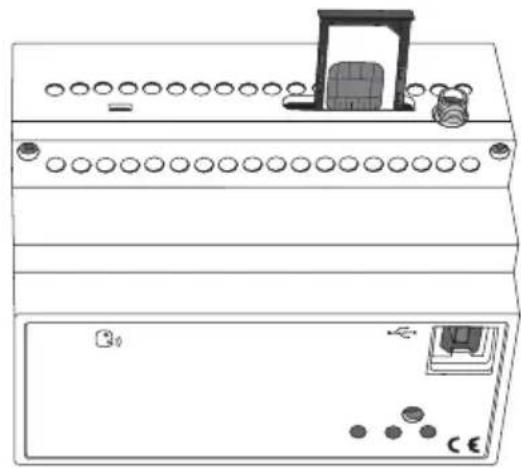
natural_image
Line drawing of an electronic device front panel with buttons and a door (no text or symbols)natural_image
Diagram of a dual-chamber electronic device with ports and connectors (no text or symbols)Mise en service
natural_image
Diagram showing connection between an electronic device and a laptop, with cable being inserted (no text or symbols present)CONNEXION PC - DISPOSITIF DE CONTRÔLE À DISTANCE
COMMANDES POUR CHRONOTHERMOSTATS OU THERMOSTATS KNX
| Commande Description | |
| CCE01-H Programme le type de fonctionnement CHAUFFAGE | |
| CCE01-C Programme le type de fonctionnement CLIMATISATION | |
| CCE01-O Programme la modalité ARRET | |
| CCE01-1 Programme la modalité ECONOMIE | |
| CCE01-2 Programme la modalité PRECONFORT | |
| CCE01-3 Programme la modalité CONFORT | |
| CCE01-A | Programme la modalité AUTO |
| CCE02-0 | Programme set point antigel |
| CCE02-1 | Programme set point ECONOMIE (chauffage) |
| CCE02-2 | Programme set point PRECONFORT (chauffage) |
| CCE02-3 | Programme set point CONFORT (chauffage) |
| CCE03-0 | Programme set point protection hautes températures |
| CCE03-1 | Programme set point ECONOMIE (climatisation) |
| CCE03-2 | Programme set point PRECONFORT (climatisation) |
| CCE03-3 | Programme set point CONFORT (climatisation) |
Max. 93% (sans condensation)
- unsigned [0..255]
- signed [-128.. +127]
- valor de porcentaje [0%.. 100%].
- unsigned [0..255]
- signed [-128.. +127]
• valor de porcentaje [0%.. 100%].
- unsigned [0 .. 65535]
• signed [-32768.. +32767] - floating point.
natural_image
Exploded view diagram of an electronic device showing battery, motor, and wiring (no text or labels)① Conexión dispositivo bus
② Conexión cable bus
natural_image
Diagram of a mechanical device with a cylindrical tool inserted into a slot, showing no text or symbols.
natural_image
Line drawing of a dual-panel electronic device with circular ports and a central display unit (no text or symbols)natural_image
Line drawing of a server rack with ports and connectors (no text or symbols)Puesta en servicio
natural_image
Line drawing of an electronic device connected to a laptop via cable, showing ports and wiring (no text or symbols present)MAYÚSCULAS Y MINÚSCULAS
- unsigned [0..255]
- signed [-128.. +127]
- Prozentwert [0%.. 100%].
- unsigned [0..255]
- signed [-128.. +127]
• Prozentwert [0%.. 100%].
- unsigned [0 .. 65535]
• signed [-32768.. +32767] - floating point.
natural_image
Pure electrical circuit lines without any symbolsnatural_image
Mechanical assembly diagrams showing two configurations with arrows indicating force or movement (no text or symbols present)Anschlussbeispiele
BUILDING AUTOMATION SYSTEM
flowchart
graph TD
    A["Mobile Phone"] -->|230 V~| B["GSM EIB Fernsteuerung"]
    B --> C["Antenne"]
    B --> D["230 V"]
    D --> E["bus KNX/EIB"]
    E --> F["230 V"]
    F --> G["COM AUF AB"]
    F --> H["NC COM NO"]
    F --> I["230 V"]
    I --> J["230 V"]
    J --> K["230 V"]
    K --> L["230 V"]
    L --> M["230 V"]
    M --> N["230 V"]
    N --> O["230 V"]
    O --> P["230 V"]
    P --> Q["230 V"]
    Q --> R["230 V"]
    R --> S["230 V"]
    S --> T["230 V"]
    T --> U["230 V"]
    U --> V["230 V"]
    V --> W["230 V"]
    W --> X["230 V"]
    X --> Y["230 V"]
    Y --> Z["230 V"]
    Z --> AA["230 V"]
    AA --> AB["230 V"]
    AB --> AC["230 V"]
    AC --> AD["230 V"]
    AD --> AE["230 V"]
    AE --> AF["230 V"]
    AF --> AG["230 V"]
    AG --> AH["230 V"]
    AH --> AI["230 V"]
    AI --> AJ["230 V"]
    AJ --> AK["230 V"]
    AK --> AL["230 V"]
    AL --> AM["230 V"]
    AM --> AN["230 V"]
    AN --> AO["230 V"]
    AO --> AP["230 V"]
    AP --> AQ["230 V"]
    AQ --> AR["230 V"]
    AR --> AS["230 V"]
    AS --> AT["230 V"]
    AT --> AU["230 V"]
    AU --> AV["230 V"]
    AV --> AW["230 V"]
    AW --> AX["230 V"]
    AX --> AY["230 V"]
INSTALLATION
Einsetzen der SIM
natural_image
Diagram of a mechanical device with a cylindrical tool inserted into a slot, showing no text or symbols.
natural_image
Line drawing of a dual electronic device front panel with buttons and a central display (no text or symbols)natural_image
Diagram of a dual-chamber electronic device with ports and connectors (no text or symbols)Inbetriebnahme
natural_image
Line drawing of an electronic device connected to a laptop via cable, showing ports and wiring (no text or symbols)| GSM EIB remote control unitGW 90815 | Structure of the SMS to be sent.password.command.To send more than one command, queue them one after another, separated by a full stop.password.command1.command2.command3.Caution: each SMS must finish with a full stop (“.”).Note: The character ∅ in the charts represents the number zero. | |
| Command Description | ||
| Configuration via SMS | ||
| P200-1 Send copy of messages also to the default phone number | ||
| P200-0 Do not send copy of messages also to the default phone number | ||
| P403-telephone | Telephone number to which SMS are sent for 1 bit input 1 | |
| P408-telephone | Telephone number to which SMS are sent for 1 bit input 2 | |
| P413-telephone | Telephone number to which SMS are sent for 1 bit input 3 | |
| P418-telephone | Telephone number to which SMS are sent for 1 bit input 4 | |
| P423-telephone | Telephone number to which SMS are sent for 1 bit input 5 | |
| P428-telephone | Telephone number to which SMS are sent for 1 bit input 6 | |
| P433-telephone | Telephone number to which SMS are sent for 1 bit input 7 | |
| P438-telephone | Telephone number to which SMS are sent for 1 bit input 8 | |
| P443-telephone | Telephone number to which SMS are sent for 1 bit input 9 | |
| P448-telephone | Telephone number to which SMS are sent for 1 bit input 10 | |
| P453-telephone | Telephone number to which SMS are sent for 1 bit input 11 | |
Cut and fold this guide into four so you can always carry the most common commands with you at all times
| KNX timed-thermost or thermostat commands | Command | Description | |
| Configuration via SMS (continued) | |||
| 4P58-telephone | Telephone number to which SMS are sent for 1 bit input 12 | CCE01-H sets the function type: HEATINGG | |
| P463-telephone | Telephone number to which SMS are sent for 1 bit input 13 | CCE01-C sets the function type: CONDITIONINGG | |
| P473-telephone | Telephone number to which SMS are sent for 1 bit input 15 | CCE01-1 sets ECONOMY mode | |
| P488-telephone | Telephone number to which SMS are sent for 1 bit input 16 | CCE01-2 sets PECOMFORT mode | |
| P483-telephone | Telephone number to which SMS are sent for 1 bit input 8 | CCE01-3 sets COMFORT mode | |
| P483-telephone | Telephone number to which SMS are sent for 1 bit input 16 | CCE02-0 sets tsgnptect set point | |
| P493-telephone | Telephone number to which SMS are sent for 3 bit input 8 | CCE02-1 sets ECONOMY set point (heating) | |
| P498-telephone | Telephone number to which SMS are sent for 2 bit input 8 | CCE02-2 sets PECOMFORT set point (heating) | |
| P503-telephone | Telephone number to which SMS are sent for 1 bit input 16 | CCE02-3 sets COMFORT set point (heating) | |
| P508-telephone | Telephone number to which SMS are sent for 2 bit input 16 | CCE02-3 sets COMFORT set point (heating) | |
| NOTE VALID FOR ALL CHARTS: The character 0 represents the number zero | |||
| P483-telephone | Telephone number to which SMS are sent for 1 bit input 15 | CCE01-A sets Auto mode | |
| P483-telephone | Telephone number to which SMS are sent for 1 bit input 16 | CCE01-2 sets PECOMFORT mode | |
| P488-telephone | Telephone number to which SMS are sent for 1 bit input 14 | CCE01-2 sets PECOMFORT mode | |
| P493-telephone | Telephone number to which SMS are sent for 3 bit input 8 | CCE02-1 sets ECONOMY set point (heating) | |
| P498-telephone | Telephone number to which SMS are sent for 4 bit input 8 | CCE02-2 sets PECOMFORT set point (heating) | |
| CCE03-1 sets ECONOMY set point (conditioning) | CCE03-2 sets PECOMFORT set point (conditioning) | CCE03-1 sets ECONOMY set point (heating) | |
| CCE03-3 sets COMFORT set point (conditioning) | CCE03-4 sets COMFORT set point (conditioning) | CCE03-1 sets ECONOMY set point (heating) | |
| CCE03-3 sets COMFORT set point (conditioning) | CCE03-3 sets COMFORT set point (conditioning) | ||
| CCE02-1 | Output n: OF/F/Overnide off/Scene A on/Snutter UP | ||
| CCE02-2 | Output n: Learning scene A | ||
| CCE02-3 | Output n: Learning scene B | ||
| CVE0N-1 | 8 bit object in: send value 1 | ||
| CVE0N-2 | 8 bit object in: send value 2 | ||
| CVE0N-3 | Output n: Learning scene B | ||
| CVE0N-4 | Output n: Learning scene A | ||
| 8 bit output commands | |||
| Replace n with the 8 bit output number to be controlled (n=1..4) | |||
| 16 bit output commands | |||
| CVE05-1 | 16 bit object 1: send value 1 | ||
| CVE05-2 | 16 bit object 1: send value 2 | ||
| CVE06-1 | 16 bit object 2: send value 1 | ||
| CVE06-2 | 16 bit object 2: send value 2 | ||
| Status request commands | |||
| CSE00-0 | Status request for all managed KXN inputs and devices | ||
| SCE00-1 | Status request for KXN inputs | ||
| SCE00-2 | Device status request for thermal regulation | ||
| SCE00-3 | Status request for blarger alarm system | ||
Instructions
Commande | Description
Programmations via SMS
Indicator remoto GSM EIB

- Invio valori 16 bit
- INSTALLAZIONE
- Messa in servizio
- COLLEGAMENTO PC - REMOTIZZATORE
- MAIUSCOLE E MINUSCOLE
- COMANDI USCITE A 8 BIT
- COMANDI USCITE A 16 BIT
- PROGRAMMING
- IN SERVICE
- TECHNICAL DATA ....51
- GENERAL INFORMATION
- Pack content
- Summary
- Functions
- generic output command
- GENERAL DESCRIPTION
- Send 8 bit values
- Send 16 bit values
- bit input management
- bit input management
- Each object can be linked to:
- bit input management
- Thermal regulation
- MESSAGES SENT BY THE REMOTE CONTROL UNIT
- Warnings for KNX/EIB installations
- Warnings for installation phase
- Verification of GSM signal cover
- SIM
- Assembly on the DIN Rial
- INSERTING THE BATTERIES
- Electrical connections
- WARNING: disconnect the network voltage before connecting the device to the power network!
- Connection examples
- INSTALLATION
- SIM insertion
- Aerial position and connection
- Commissioning
- Physical address programming
- Configuration procedures
- Password
- PC configuration
- CONNECTING THE PC TO THE REMOTE CONTROL UNIT
- USING THE CONFIGURATION SOFTWARE
- Interaction and configuration via SMS
- UPPER CASE AND LOWER CASE
- STRUCTURE OF THE SMS SENT
- MULTIPLE COMMANDS
- CUSTOMISED TEXTS
- TELEPHONE NUMBERS
- Basic configuration
- Configuration via SMS
- CONFIGURATION OF KNX OUTPUTS
- CONFIGURATION OF KNX THERMAL REGULATION
- CONFIGURATION REQUEST
- Final Inspection
- Remote control via SMS
- BURGLAR ALARM SYSTEM COMMANDS
- 8-BIT OUTPUT COMMANDS
- 16-BIT OUTPUT COMMANDS
- KNX TIMED-THERMOSTAT OR THERMOSTAT COMMANDS
- Local indications
- Emergency blackout function
- Cleaning the remote control unit
- Replacing the batteries
- WARNING
- Recharging the SIM
- TECHNICAL DATA
- Default values
- SOMMAIRE
- AVERTISSEMENTS GÉNÉRAUX
- DESCRIPTION GENERALE
- Mise en service
- CONNEXION PC - DISPOSITIF DE CONTRÔLE À DISTANCE
- COMMANDES POUR CHRONOTHERMOSTATS OU THERMOSTATS KNX
- Puesta en servicio
- MAYÚSCULAS Y MINÚSCULAS
- Anschlussbeispiele
- Einsetzen der SIM
- Inbetriebnahme
- Instructions
Brand : Gewiss
Model : GW90815
Category : Electrical control device