
GW90821 - Remote control device Gewiss - Free user manual and instructions
Find the device manual for free GW90821 Gewiss in PDF.
| Product type | GSM remote control device with I/O and serial line for DIN rail |
| Brand | Gewiss |
| Model | GW90821 |
| Power supply | 230 V AC + 3 rechargeable NiMH AAA backup batteries (recommended capacity 800 mAh or more) |
| Communication | Quad-band GSM network, SMS |
| Outputs | 2 relays 10 A (AC1) / 4 A (AC15) - 250 Vac, voltage-free NO contacts |
| Inputs | 2 digital inputs 12 V AC/DC ÷ 250 V AC, minimum pulse duration 500 ms |
| Serial connections | Screw terminals, max. cable cross-section 2.5 mm², max. length 20 m |
| RF interfaces | Connectors for RF command/control interface (4 channels) and anti-theft (6 channels) |
| PC port | 1 USB type B port |
| Dimensions | 6 DIN modules (width approx. 106 mm) |
| Weight | Approximately 300 g (estimated) |
| Operating temperature | -5 to +45 °C |
| Storage temperature | -25 to +70 °C |
| Relative humidity | Max. 93 % (non-condensing) |
| Protection degree | IP20 |
| Mounting | On 35 mm DIN rail |
| Main functions | Remote control of loads via SMS, alarm reception on phone, management of electronic chronothermostat/programmer, interaction with RF systems (anti-theft, command/control) |
| Maintenance and cleaning | Clean with a dry cloth. Replace all 3 batteries at the same time with NiMH AAA of the same capacity. |
| Safety | Installation by qualified personnel according to IEC 64-8 standard. Use a magnetothermal circuit breaker upstream. Cut off power before any intervention. |
| Spare parts and repairability | Antenna, 1.5 m extension cable, double-sided adhesive tapes supplied. No spare parts available; device not user-repairable. |
| General information | Manual available in several languages. Configurable via PC via USB or by SMS. Password 4 alphanumeric characters. |
Frequently Asked Questions - GW90821 Gewiss
User questions about GW90821 Gewiss
0 question about this device. Answer the ones you know or ask your own.
Ask a new question about this device
Download the instructions for your Remote control device in PDF format for free! Find your manual GW90821 - Gewiss and take your electronic device back in hand. On this page are published all the documents necessary for the use of your device. GW90821 by Gewiss.
USER MANUAL GW90821 Gewiss

INTERFACCIA SISTEMA ALLARME RF
INSTALLAZIONE
Inserimento SIM
MAIUSCOLE E MINUSCOLE
CONFIGURAIZIONE USCITE RF
| Prima Dopo | |||
| relè 1 rele 2 relè 1 rele 2 | |||
| OFF OFF | ON ON | ||
| ON OFF | OFF OFF | ||
| OFF ON | OFF OFF | ||
| ON ON | OFF OFF | ||
Contents of the pack 30
GENERAL DESCRIPTION
Summary 31
Functions 32
INSTALLATION
Warnings for installation phase 34
Verification of GSM signal cover 34
SIM 34
Assembly on the DIN Rail 35
Electrical connections 37
Serial connections 38
Interface connections 40
SIM insertion 42
Aerial position and connection 43
Commissioning 43
PROGRAMMING
Configuration Procedures 44
Password 44
PC configuration 44
Interaction and configuration via SMS 45
Basic configuration 46
Configuration via SMS 46
Final Inspection 49
IN SERVICE
Remote control via SMS 50
Local indications 51
Local commands 52
Emergency Blackout Function 52
Cleaning the repeater 52
Replacing the batteries 52
Recharging the SIM 52
Default values 53
TECHNICAL DATA 54
Default values 54
GENERALWARNINGS
Warning! The safety levels of this device can only be guaranteed if these instructions are fully observed. It is therefore essential to carefully read and keep them for future reference. All Chorus products must be installed in compliance to CEI 64-8 Standards for household appliances and similar items, in dust-free environments where no special protection is required to prevent penetration of water.
The GEWISS sales division is at your complete disposal for any further technical details or information you may require.
Gewiss SpA reserves the right to make any modifications to the products described in this manual at any time without prior warning.
Contents of the pack
n. 1 GSM repeater with I/O and serial line - DIN Rail
n.1 Aerial
n. 1 Aerial extension cable 1.5m
n. 2 Double-sided adhesive
n. 1 Installation and user manual
Summary
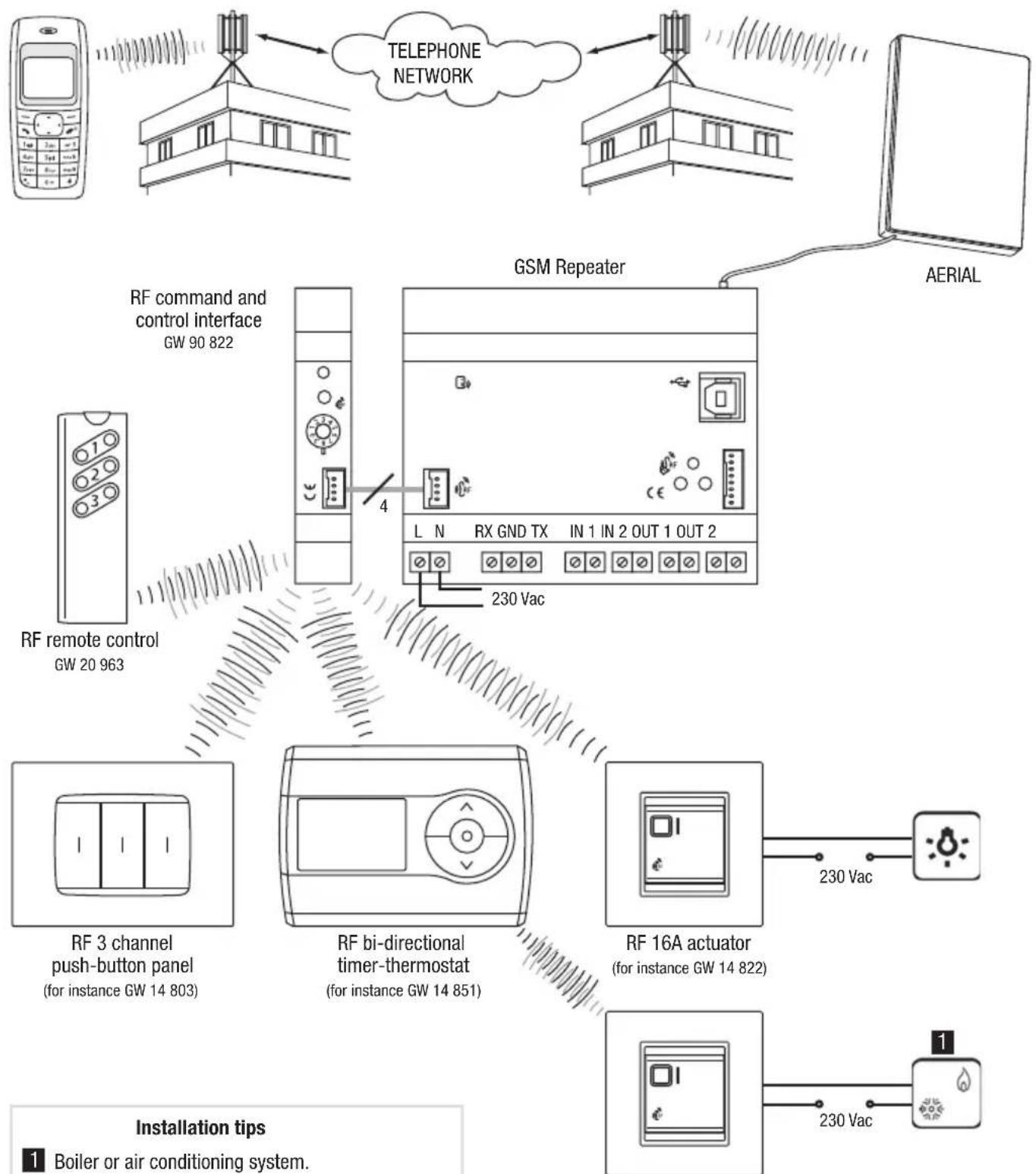
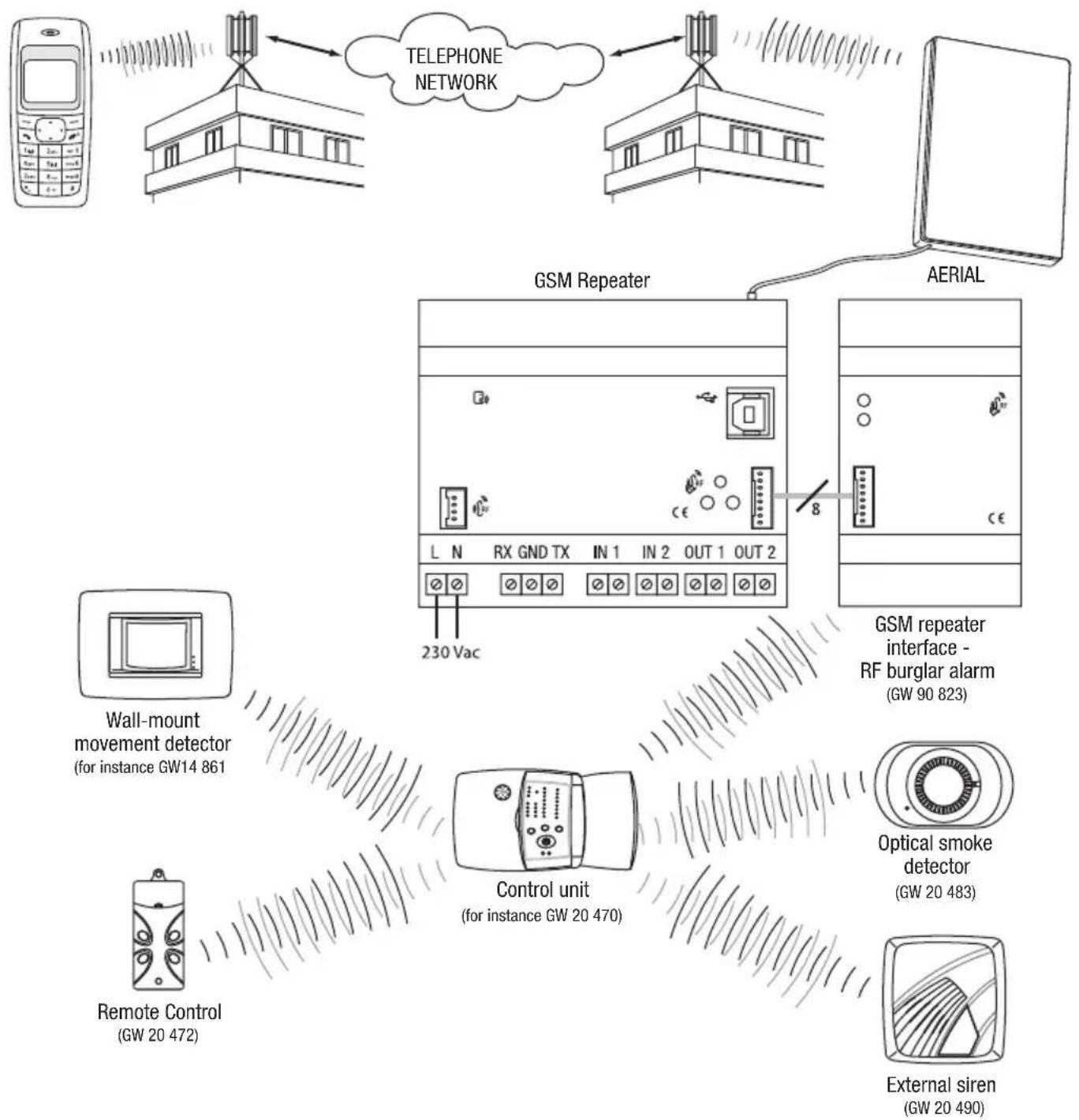
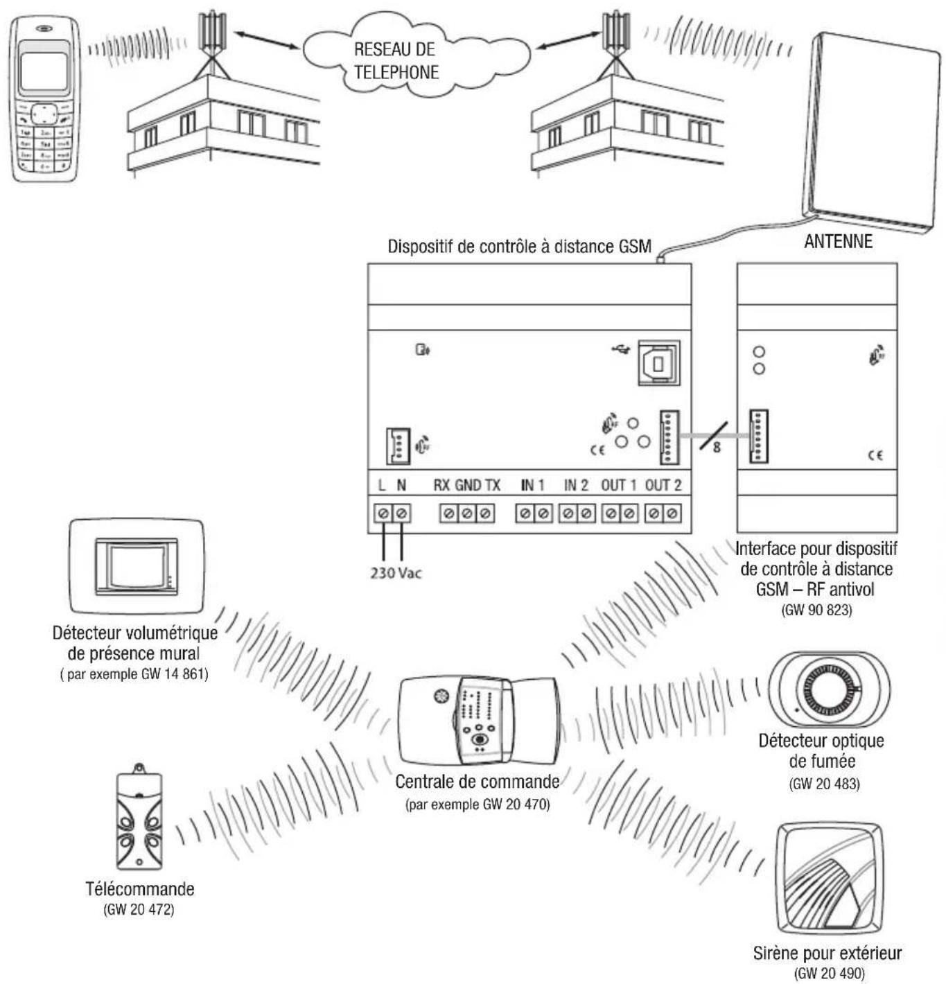
The GSM repeater with I/O and serial line - DIN Rail allows you to remotely control electrical charges through two relays without potential contacts using SMS messages sent from a cell phone, and to receive status and alarm signals from two digital inputs directly on your cell phone. The relay commands can be bistable, timed or impulse; the inputs are able to detect a status or an edge change. The serial line connection fitted on the repeater allows you to handle an electronic programming unit (for instance a GW 14 581) or a timer-thermostat (for instance GW 14 701, GW 10 703, GW 14 841). It is therefore possible to remotely control, for instance the enabling/disabling programme on the electronic programming unit, or set the function modes for the thermal regulation system and request the function parameters and the room temperature. Using the relative interface it is also possible to interact remotely with the following Gewiss systems:
- RF burglar alarm system, for total or partial arming of the system, disabling or status request, and to receive automatic burglar alarm activation, tampering, malfunction and panic signals;
- RF control and command, enabling or disabling of charges connected to RF actuator modules, receiving of signals from transmitters such as push-button panels, sensors and remote controls, or control and request status of a bidirectional RF timer-thermostat; The repeater is fitted with a rechargeable back-up battery to power it when the network power is down: it is therefore possible to detect a blackout and the RF burglar alarm system can send alarm, malfunction or tamper signals. The repeater is customised using a PC connected to the device through a USB port, using the configuration software, or by sending codes by SMS.
The repeater is fitted on a 35mm DIN Rail, inside electric panels or junction boxes.
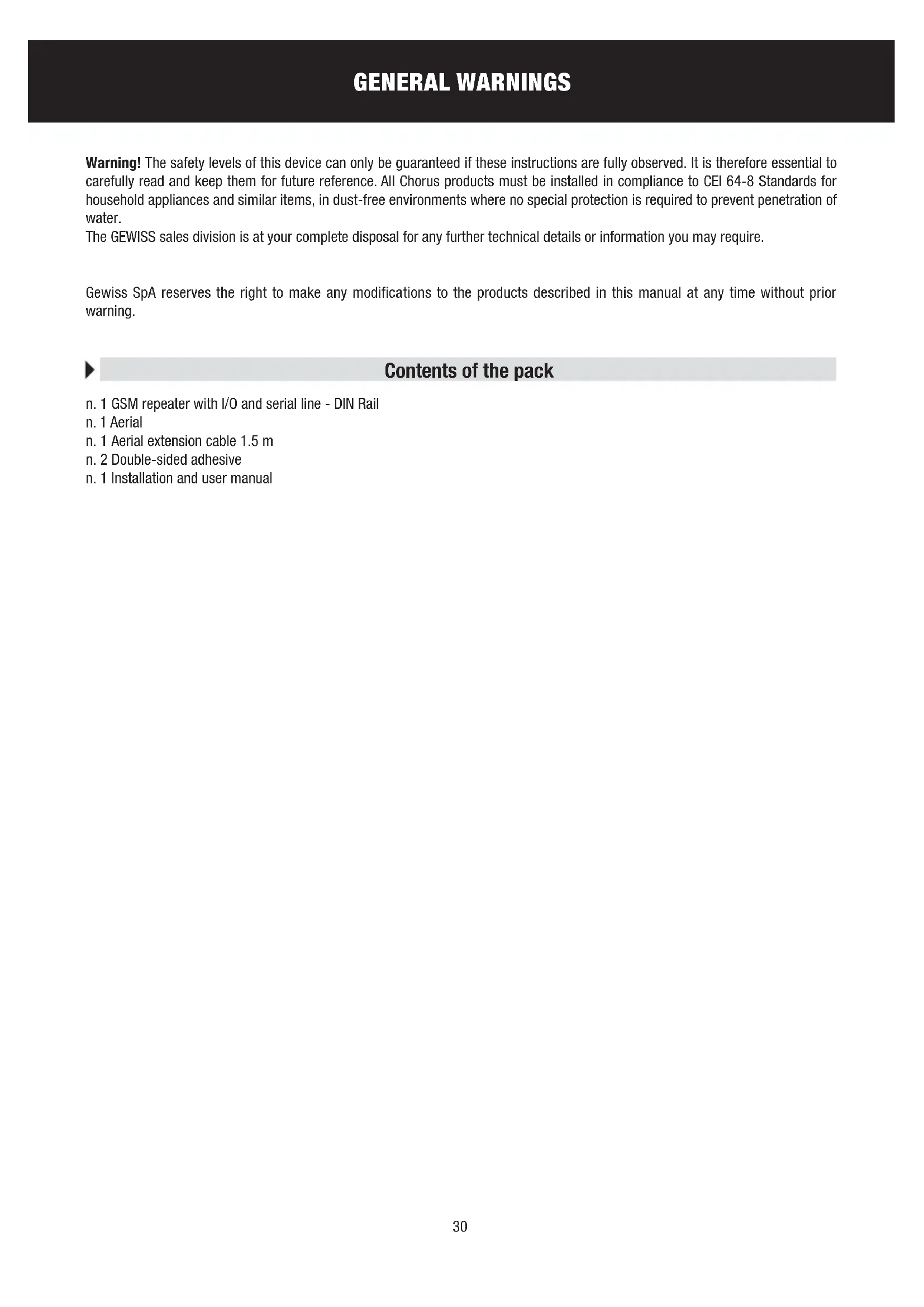
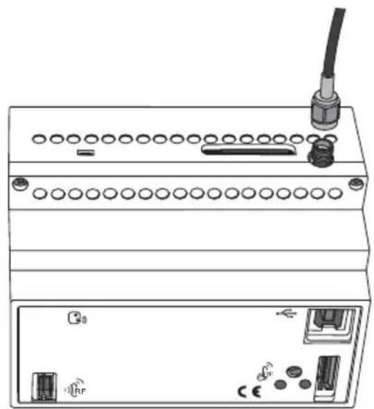
① 230Vacpower
② Serial line:
③ Input 1
④ Input 2
⑤ Output relay 1
⑥ Output relay 2
⑦ Device status indicator LED
8 Multi-function GSM module status indicator LED
GSM repeater - RF burglar alarm system connection interface
10 Output relay switching button
USB Port (type B)
12 External aerial connection
SIM card slot
GSM repeater - RF burglar alarm system command and control connection interface
Functions
MANAGEABLE FUNCTIONS
The chart below lists the functions that can be managed by the repeater, directly or through other Gewiss devices.
| With internal inputs and outputs | With timer-thermostat and serial connection | With electronic programmer and serial connection | With RF devices and interface (GW 90 822) | With RF burglar alarm and interface (GW 90 823) | |
| Output relay switching | ■ (1) (2) | ■ | |||
| Output relay timer switching | ■ | ■ (5) | |||
| Output relay impulse switching | ■ | ||||
| Motor command (e.g. shutters) | ■ | ||||
| Sending of SMS on receiving "ON" | ■ | ■ | |||
| Sending of SMS on receiving "OFF" | ■ | ■ | |||
| Sending of SMS on receiving "ON" and "OFF" | ■ | ■ | |||
| Sending of SMS only on request | ■ | ■ | |||
| Setting of timer-thermostat function type (heating/air conditioning); | ■ | ■ (3) | |||
| Setting of thermal regulation system function mode (auto/manual/OFF); | ■ | ■ (3) | |||
| Manual setting of the set point | ■ | ■ (3) | |||
| Request for timer-thermostat status | ■ | ■ (3) | |||
| Activation of manual mode with output ON | ■ | ||||
| Activation of manual mode with output OFF | ■ | ||||
| Activation of AUTO mode | ■ | ||||
| Request for electronic programmer status | ■ | ||||
| Total arming of the alarm system | ■ | ||||
| Partial arming of the alarm system (zone 1) | ■ | ||||
| Partial arming of the alarm system (zone 2) | ■ | ||||
| Complete disarming of the burglar alarm system | ■ | ||||
| Request for burglar alarm status | ■ | ||||
| Alarm signal | ■ (4) |
(1) The output relays are bistable, therefore when the blackout ends they maintain the previously set status. If the output relays are configured as timers they will open at the end of a blackout.
(2) It is possible to open the local relay contacts by pressing the front button on the repeater.
(3) With the wall bidirectional RF timer-thermostat (GW 10 851 - GW 14 851).
(4) Signal sent automatically if the burglar alarm goes off, if there is tampering, a malfunction or panic alarm signal.
(5) The timing intervals are counted by the RF actuator and not by the repeater. At the end of the blackout the relay will return to the OFF status.
MESSAGESENT BY THE REPEATER
The repeater sends - following a direct request, in response to an order received or the indication of an event in progress - the messages below:
| Send to calling number | Send to default number | Default Text | Customised Text | |
| Confirmation of execution of a command after sending a request | ||||
| Internal relay switching | ■ | ▲ | ■ | |
| RF device relay switching | ▲▲■ | |||
| Motor command | ▲▲■ | |||
| Setting of timer-thermostat function type | ▲▲■ | |||
| Setting of timer-thermostat function mode | ▲▲■ | |||
| Setting of electronic programmer function mode | ▲▲■ | |||
| Arming/disarming of the burglar alarm system | ■ | ■ | ||
| Activation/deactivation signal of arming/disarming | ■ | ■ | ||
| Status signals sent automatically | ||||
| Variation in local input status | ■ | ■ | ||
| Variation in RF device input status | ■ | ■ | ||
| Burglar system alarm indicator | ■ | ■ | ||
| Status indicator in response to a request | ||||
| Status request for all managed devices | ▲▲■ | |||
| Status request for the local I/O and SF subsystems | ▲▲■ | |||
| Status request for timer-thermostats (1) | ▲▲■ | |||
| Status request for electronic programmer (2) | ▲▲■ | |||
| Status request for burglar alarm system (3) | ■ | ■ | ||
The reply is sent to the default telephone number if the calling number is hidden.
(1) The reply includes the current function type and mode, the currently set temperature set point, the room temperature and the actuator status (ON/OFF), except for the RF timer-thermostats where the sent command is notified as the actuator does not respond to the command.
(2) The reply includes the function mode and contact status.
(3) The reply includes the system status (armed/disarmed) the unit status (ready/not ready for arming), alarm memory, tamper memory, malfunction memory and the burglar alarm system arming/disarming notice status.
The SMS that confirm that a command has been executed and indicate the status of devices, and are sent by the repeater after receiving a request, are sent to the calling number, none excluded (upon entering the password).
The only exception is the burglar alarm status, which must be sent by a telephone number memorised in the SIM as the default number for controlling the burglar alarm system.
The status indicator SMS sent autonomously by the repeater are sent to the numbers indicated during the setup procedure or, if not specified, to the default telephone number. The only exceptions are the burglar alarm signals, which are sent to the telephone numbers memorised in the SIM as the default number for controlling the burglar alarm system.

WARNING: only qualified personnel are permitted to install this device, according to the regulations in force.
Warnings for installation phase
The repeater uses radiofrequency connections for remote and GSM wireless connections and to interact with the RF burglar alarm system and the RF command and control system through the relative RF interfaces.
It is therefore essential to adopt a series of precautions:
- position the repeater aerial and any RF interfaces as far as possible from all sources of electromagnetic disturbances, such as electrical motors, electricity meters, dimmers, fluorescent lights;
- NEVER install the repeater aerial and any RF interfaces inside control panels or metal cabinets;
- NEVER install the repeater aerial and any RF interfaces in front or behind metal panels;
- make sure that any RF interfaces are able to dialogue with the foreseen devices, before installation is completed; perform some preliminary wireless connection tests (please refer to the technical manuals for each interface for further instructions).
It is recommended to install a short-circuit protection device upstream of the repeater (for instance a magnetothermal switch) which can be useful for sectioning the line during maintenance or modifications to the repeater connections.
Verification of GSM signal cover
The repeater works with all GSM mobile phone providers. It is necessary however that the GSM network provider covers the selected installation zone and that the GSM signal is sufficiently strong. To check the signal, use a cell phone with a SIM card connected to the provider from the exact position you intend to install the units. If the signal is weak or not available, proceed as follows:
- Try another position, until you find an acceptable signal level.
- Try repositioning the aerial or replacing it with a compatible type (see the Positioning and connecting the aerial paragraph).
- Try using a SIM card connected to a different provider (the GSM cover varies from provider to provider).
It is possible to check if the signal level is acceptable using the multifunction GSM module status indicator LED: fixed green light indicates good level, red indicates no GSM signal.

WARNING: if there is no GSM signal the device cannot receive or send SMS.
SIM
The repeater accepts both SIM contract cards and prepaid SIM cards. If you use a prepaid SIM card, you have to bear in mind some aspects which could compromise standard operations.
- Recharging the SIM: when the prepaid SIM card runs out, the repeater can no longer send messages. The repeater does not send a "SIM credit finished" notice, therefore you have to remember to check that there is always sufficient credit to allow for remote communications.
- SIM expiry dates: Most mobile phone providers deactivate prepaid SIM cards 11/12 months from when they were last recharged, whatever the residual credit. This problem can be overcome by enabling the automatic SIM card recharge service which most mobile phone providers supply.
- Unlocking SIM cards: If you use a new SIM card you may have to make a phone call to unlock it.
To do this you have to place the SIM card in a normal cell phone and make the phone call.
- Disabling the PIN code option: It is essential to disable the GSM PIN code request option on the SIM card before installing it in the repeater. To do this you have to place the SIM card in a normal cell phone and follow the instructions supplied with the cell phone.
It is recommended to test that the basic functions work, such as sending an SMS, to check that all the SIM settings (SMS centre number etc) are all correct.
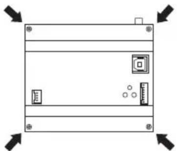
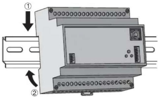
Assembly on the DIN Rail
INSERTING THE BATTERIES
Before fitting the repeater on the DIN Rail, insert the back-up rechargeable batteries as follows:
- Unscrew the four screws on the front of the repeater and press the top and bottom notches together to release the cover.
- Insert 3 NiMh - AAA rechargeable batteries, making sure the poles are in the right direction. It is recommended to use batteries which are 800mAh or higher.
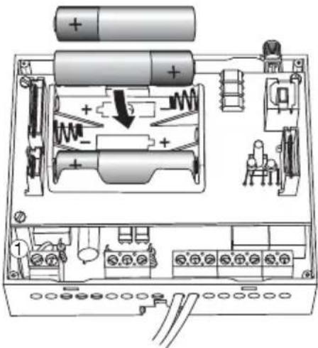
- Replace the cover on the repeater and fix it in place with the screws.
ASSEMBLY ON THE DIN RAIL
Assemble the repeater onto the 35mm DIN Rail as follows:
- Insert the device's upper coupling in the DIN Rail.
- Rotate the device until you hear a "click" that means that the DIN Rail is blocked in place.
INSTALLATION
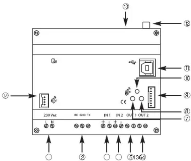
CONNECTING THE INTERFACES
Before connecting the interfaces, remove the pre-cut labels that cover the connectors, as seen in the image below. Use a screwdriver to help you lift the label, making sure you do not damage the connector underneath.
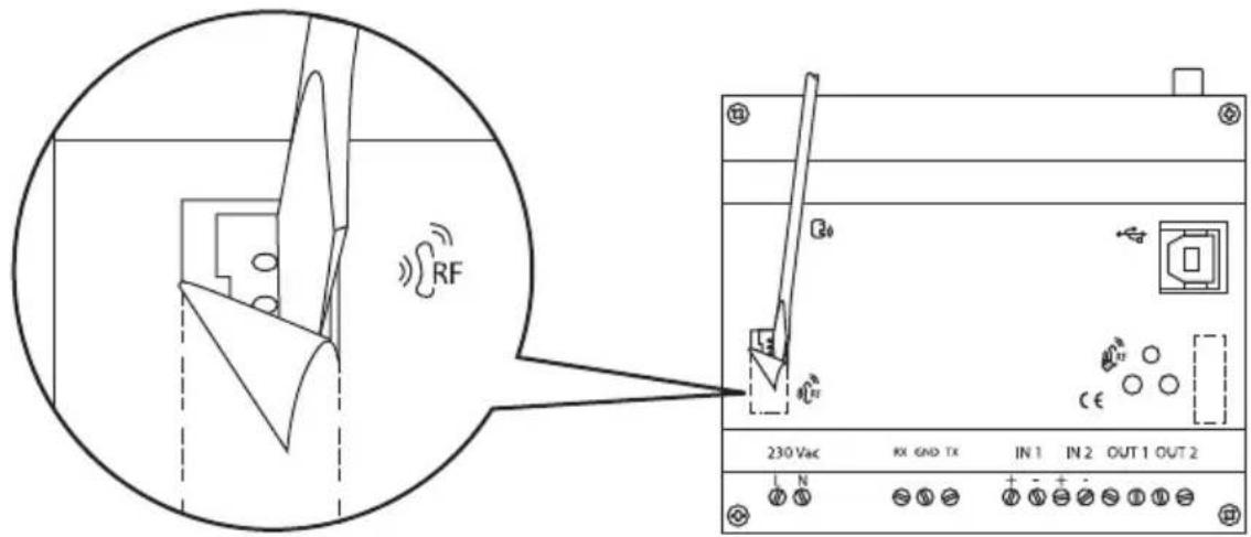
Position the interfaces to the side of the repeater, bearing in mind the length of the connection cables, with the polarized connectors supplied.
Electrical connections
1 The loads connected to the outputs must never exceed the repeater relay switching capacity. If you connect high voltage loads we recommend you use the repeater to command a voltage relay which will connect the relative loads.
2 12V ac/dc 4÷ 250V ac electric signals can be connected to the inputs. The polarity must be observed if continuous current signals are connected.
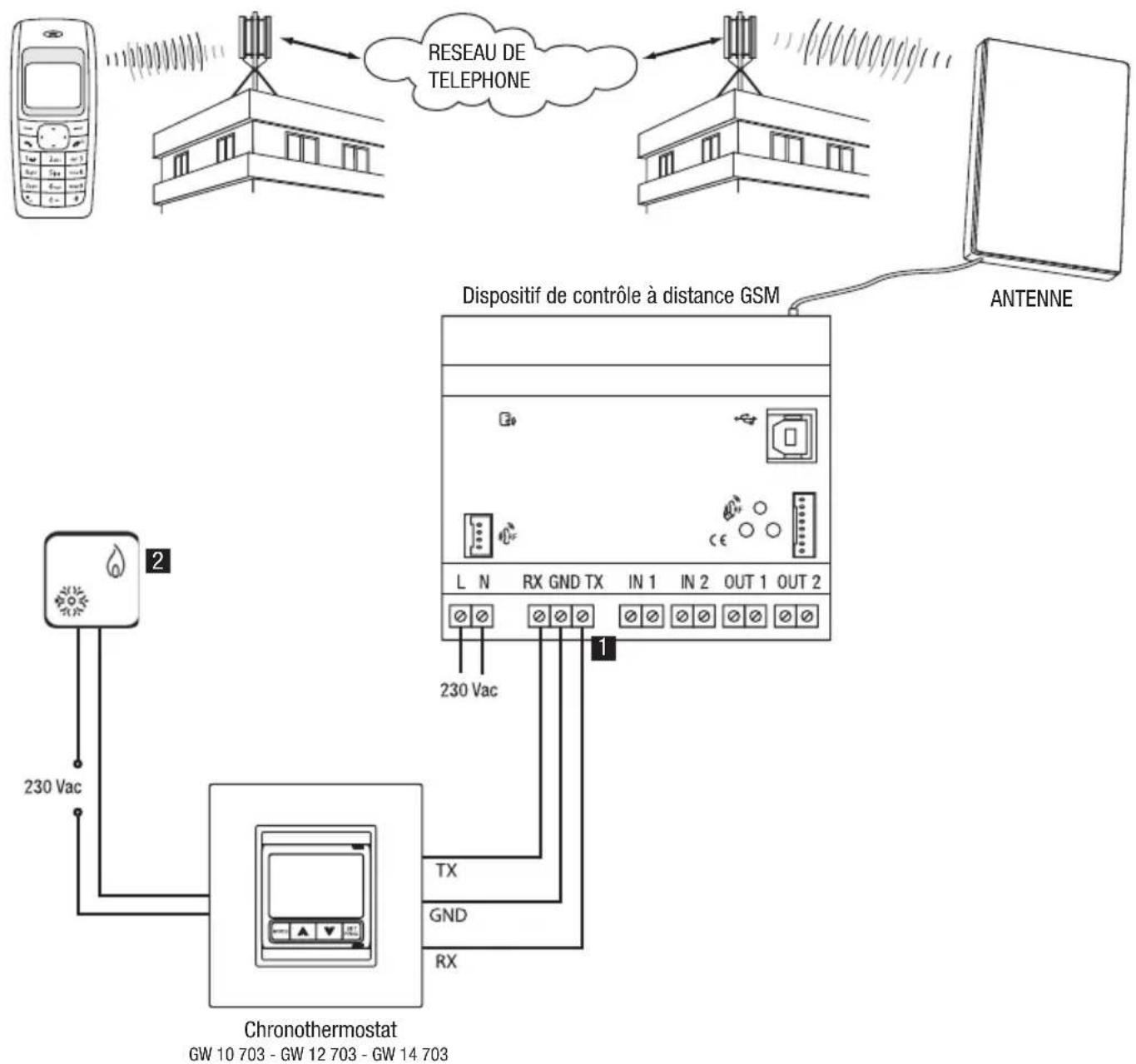
Serial connections
FLUSH-MOUNT TIMER-HERMOSTAT
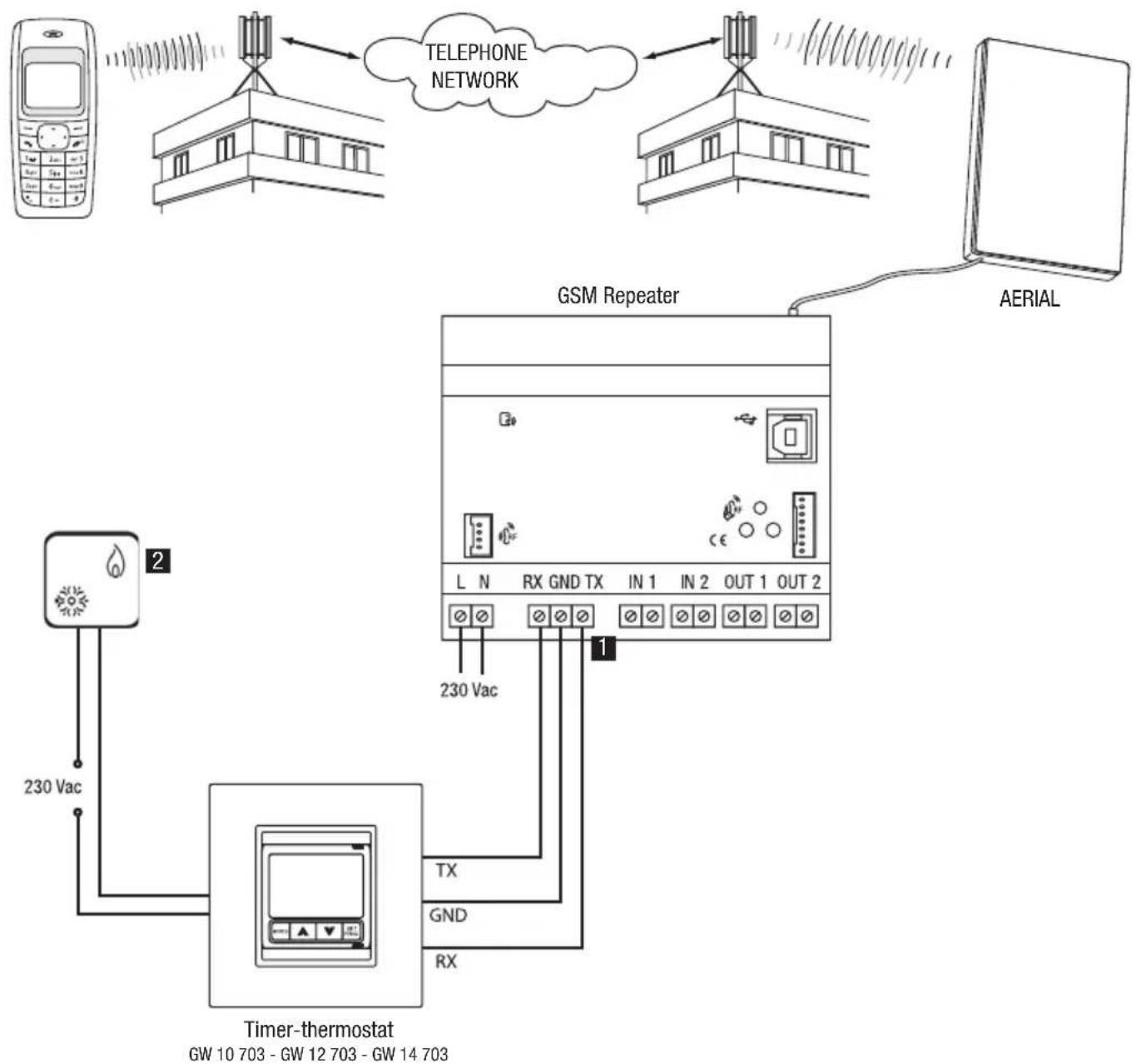
Installation tips
1 Standard copper conductors can be used for the serial connection. Max serial connection length: 20m
2 Boiler or air conditioning system.
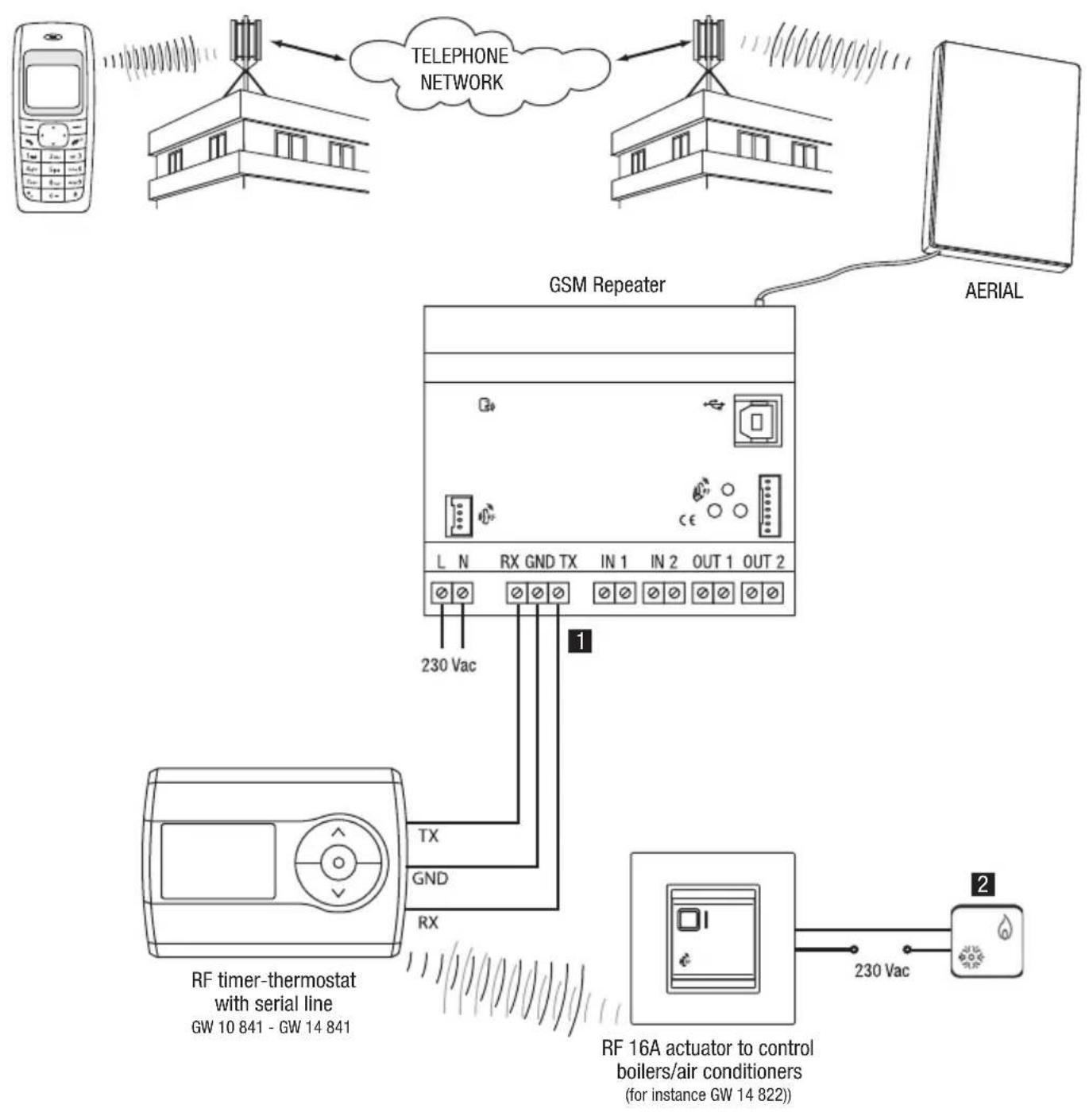
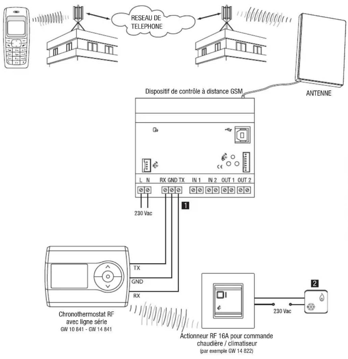
RF WALL-MOUNT TIMER-HERMOSTAT
Installation tips
1 Standard copper conductors can be used for the serial connection. Max serial connection length: 20m
2 Boiler or air conditioning system.
Interface connections
RF COMMAND AND CONTROL DEVICE INTERFACE
RF 16A actuator to control boilers/air conditioners (for instance GW 14 822)
Installation tips
1 Boiler or air conditioning system.
RF ALARM SYSTEM INTERFACE
INSTALLATION
SIM insertion
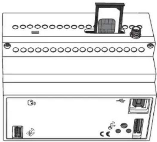
To insert the SIM card inside the repeater:
- Use a biro or pencil to press the little yellow release button to the side of the SIM card slot.
- Open the SIM card slot.
- Insert the SIM card in the slot making sure the rounded edge faces the top right corner and the gold contacts are visible.
- Close the SIM card slot.
Releasing the SIM card slot SIM connection position
INSTALLATION
Aerial position and connection
Make sure you position the repeater aerial:
- as far as possible from all sources of electromagnetic disturbances, such as electrical motors, electricity meters, dimmers, fluorescent lights;
- outside electric panels or metal cabinets;
- at a distance from any metal panels;
- in a dry area (the aerial casing is not waterproof);
- in a protected place, to prevent accidental or intentional damage.
The aerial can be fixed to a wall or a smooth surface using the double-sided adhesive strips supplied with the pack. The repeater is supplied with a 1.5m aerial extension to make it easier to position the aerial. This extension should only be used if necessary.
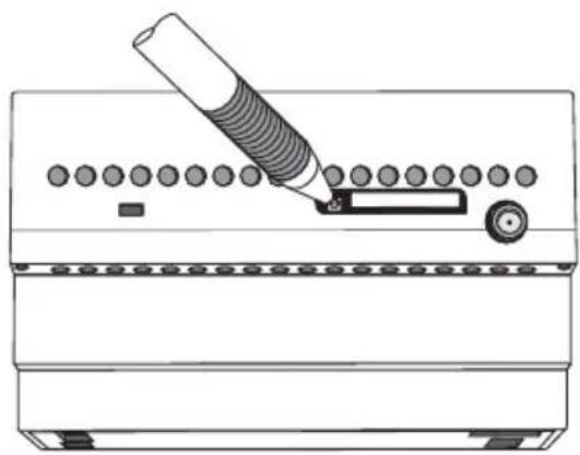
Connect the aerial by screwing its cable onto the SMA connector situated at the top of the repeater. Screw it on by hand, without using any tools, to make sure you don't damage the connector.
Commissioning
After connecting the device to the power supply, the device status indicator LED will start to flash to inform you that the GSM module initialising phase is in progress.
After around 30 seconds the LED will show a fixed green light: this means that the device has been correctly initialised. If the GSM module status indicator LED is green, it means that the GSM network is available; if it is red, this means that the GSM signal is too weak.
PROGRAMMING
Configuration Procedures
The repeater can be configured using a PC, connected to the device with a USB cable, using the configuration software, or by cell phone by sending SMS.
The first procedure is recommended the first time you install and configure the device, whilst the second procedure is particularly useful when you have to remotely configure the repeater. In order for the repeater to work properly, you have to configure the following.
- Access password.
- Reply default telephone number
- Telephone numbers (optional) authorised to control the burglar alarm system or modify the parameters
- Enable the various interfaces
- Local inputs: enable event, message text relative to the event, telephone number for SMS sending (only if different from the default number).
- Local outputs: function type (impulse, bistable, timed), duration of the contact closure (only when it functions in impulse or timed mode), text of the confirmation message.
- RF Interface: conditions for SMS sending, message text, telephone number for SMS sending (only if different from the default number).
Password
The password is needed by the repeater to identify the caller before performing the instructions received via SMS. The password consists in 4 alphanumeric characters, chosen by the user from 0...9, a...z, A...Z.
The repeater recognises upper case and lower case letters, therefore "ab12" is different from "AB12".
To save the password, please refer to the Basic Settings paragraph.
PC configuration
CONNECTING THE PC TO THE REPEATER
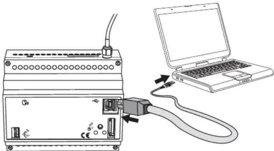
If you intend to configure the repeater using a PC, it must be connected to the power supply.
USING THE CONFIGURATION SOFTWARE
The software used to configure the device from the PC can be downloaded from our website www.gewiss.com - browse to the GSM repeater with I/O and serial line GW 90 821 page.
The software user manual is also available in the same section.
Interaction and configuration via SMS
The repeater accepts commands and queries via SMS for the devices or systems it is connected to. The commands are always received by the repeater after entering the password, from all incoming telephone numbers, visible or hidden. This is not the case for the configuration commands and all commands regarding the burglar alarm system, which can only be accessed from an incoming number which is visible and listed on the SIM memory as default numbers (please see the Basic Settings paragraph).
These are the main rules to follow when sending SMS:
UPPER CASE AND LOWER CASE
The repeater recognises upper case and lower case letters in SMS, therefore a "p" is different from a "P". All letters used in the commands and setting must be in lower case.
STRUCTURE OF THE SMS SENT
The SMS must start with a full stop (".") followed by the password (see the Password paragraph), another full stop, the command, and another full stop. No spaces are accepted between the full stops and the password or command.
Syntax: .password.Command.
Examples of correct SMS: .AB01.SGE00-0.
.AB01.P241-Stop water pump.
Examples of incorrect SMS: .AB01. SGE00-0.
.AB01.SGE00-0.
MULTIPLE COMMANDS
One SMS can be used to send multiple commands separated by a full stop ("."). The SMS must not exceed 480 characters.
Syntax:.password command1 .command2 .command3 .command4.
E.g.: .AB01.CAL01-1.CAR05-1.CCSS01-M-15,5.CAF00T.
CUSTOMISED TEXTS
The customised text or the reply messages cannot exceed 24 characters, spaces included, and must not contain full stops ("".). Other punctuation marks are allowed.
Example of a correct text message: Timer-controlled thermostat seaside
Examples of incorrect text message: Timer-thermostat seaside villa (text too long), Timer-therm. seaside villa (full stop in the text)
TELEPHONE NUMBERS
All telephone numbers must be keyed in without spaces or hyphens. The international prefix for the number must be entered using the +prefix (format (for Italy +39). The telephone that corresponds to the number must be able to receive SMS.
The numbers memorised in the repeater memory to which the SMS must be sent, must be in the international format of the Country where the repeater is installed.
The repeater only recognises the number sending the SMS if it is in the same format as the number memorised on the SIM card.
Examples of correct numbers: +39 035 94611 (spaces), 338-55523 (hyphen and no international prefix)
Examples of correct numbers: +3903594611, +3933855523
The repeater applies the following rules when sending SMS:
- The replies to commands or status queries are sent to the incoming number, if visible, or to the default number (see Basic Settings) if it is hidden.
The SMS sent autonomously by the repeater, for instance the alarms and the input switchings, are sent to the number keyed in for this specific event or, if absent, to the default number.
Basic configuration
For security reasons, some of the settings cannot be made via SMS but must be made using a cell phone directly on the SIM card to be installed on the repeater or programmed using the software.
To set these parameters from a cell phone, please proceed as follows:
- Insert the SIM you will be using for the repeater into your cell phone.
Follow the instructions provided in the cell phone manual for this operation.
- Use the cell phone display and keys to save the parameters seen in the chart below onto the SIM card
| SIM memory position | Description | Contact name on the SIM | Contact number on the SIM (1) |
| 1 Password (4 alphanumeric characters) Password – | |||
| 2 Default reply number – n. telephone | |||
| 3 | Number 1 to control the burglar alarm system and modify settings via SMS | – n. telephone | |
| 4 | Number 2 to control the burglar alarm system and modify settings via SMS | – n. telephone | |
| 5 | Number 3 to control the burglar alarm system and modify settings via SMS | – n. telephone | |
| 6 | Number 4 to control the burglar alarm system and modify settings via SMS | – n. telephone | |
| 7 | Number 5 to control the burglar alarm system and modify settings via SMS | – n. telephone | |
(1) For further information on the telephone number format on the SIM card, please refer to the Telephone number paragraph.
The alarm messages will be sent to all the numbers indicated under the burglar alarm system section.
To save the information on the SIM card, please proceed as follows:
a) select the memory position as required;
b) leave the "contact name" field empty, except if a password is required; in this case enter the chosen password;
c) key in the telephone number in the "contact number" field (the password does not require a phone number; any phone numbers will be ignored).
Before proceeding and saving the numbers and the password on the SIM, it is recommended to cancel all the contacts already saved on the card, to make sure that the entered numbers are saved in the listed memory fields.
Before changing the telephone numbers or the password saved on the SIM card, it is necessary to disconnect the repeater from the power supply, so that when you power it up again it will receive the new numbers saved.
It is possible to omit the telephone number for the burglar alarm command (memory positions from 3 to 7) if no RF burglar alarm GSM repeater interface (GW 90 823) is installed. In this case the configuration of the SMS parameters can only be made from the default telephone number.
- Remove the SIM card from the cell phone and replace it in the repeater as explained in the Inserting the SIM card paragraph.
WARNING: If the configuration is done using the software, the data will automatically be stored in the positions listed in the chart, overwriting any information already saved on the SIM card.
Configuration via SMS
The parameters below must be configured via SMS. The SMS is only accepted if it is sent from a visible number which corresponds to one of the numbers saved to the SIM card memory (default number and numbers authorised to configure parameters).
The underscored value is the default value.
GENERAL CONFIGURATION
| Command Description | |
| P200-1 Send copy of messages also to the default phone number | |
| P200-0 Do not send copy of messages also to the default phone number | |
| P201-1 Not used | |
| P201-0 Not used | |
| P202-1 RF Interface present | |
| P202-0 RF Interface not present | |
| P203-1 RF Burglar Alarm Interface present | |
| P203-0 RF Burglar Alarm Interface not present |
CONFIGURATION OF LOCAL INPUTS
| Command Description | |
| P240-0 INP1: SMS send condition: reception "OFF" | |
| P240-1 INP1: SMS send condition: reception "ON" | |
| P240-2 INP1: SMS send condition: reception "ON" and "OFF" | |
| P240-3 INP1: Send SMS only on request | |
| P241-text INP1: SMS message text for reception "ON" | |
| P242-text INP1: SMS message text for reception "OFF" | |
| P243-telephone | Telephone number to which SMS are sent for local input 1 |
| P250-0 INP2: SMS send condition: reception "OFF" | |
| P250-1 INP2: SMS send condition: reception "ON" | |
| P250-2 INP2: SMS send condition: reception "ON" and "OFF" | |
| P250-3 INP1: Send SMS only on request | |
| P251-text INP2: SMS message text for reception "ON" | |
| P252-text INP2: SMS message text for reception "OFF" | |
| P253-telephone | Telephone number to which SMS are sent for local input 2 |
CONFIGURATION OF LOCAL OUTPUTS
| Command Description | |
| P280-0 OUT1: Bistable switching mode | |
| P280-1 OUT1: Impulse switching mode | |
| P280-2 OUT1: Timer switching mode | |
| P281-0 OUT1: Duration 1 | [bistable: NO; impulse = 300ms; timed = 30sec] |
| P281-1 OUT1: Duration 2 | [bistable: NA; impulse = 500ms; timed = 60sec] |
| P281-2 OUT1: Duration 3 | [bistable: NO; impulse = 800ms; timed = 5 min] |
| P281-3 OUT1: Duration 4 | [bistable: NO; impulse = 1 sec; timed = 10 min] |
| P281-4 OUT1: Duration 5 | [bistable: NO; impulse = 2 sec; timed = 30 min] |
| P281-5 OUT1: Duration 6 | [bistable: NO; impulse = 5 sec; timed = 1 h] |
| P281-6 OUT1: Duration 7 | [bistable: NO; impulse = 10 sec; timed = 2 h] |
| P282-text OUT1: SMS confirmation message text | |
| P290-0 OUT2: Bistable switching mode | |
| P290-1 OUT2: Impulse switching mode | |
| P290-2 OUT2: Timer switching mode | |
| P291-0 OUT2: Duration 1 | [bistable: NO; impulse = 300ms; timed = 30sec] |
| P291-1 OUT2: Duration 2 | [bistable: NO; impulse = 500ms; timed = 60sec] |
| P291-2 OUT2: Duration 3 | [bistable: NO; impulse = 800ms; timed = 5 min] |
| P291-3 OUT2: Duration 4 | [bistable: NO; impulse = 1 sec; timed = 10 min] |
| P291-4 OUT2: Duration 5 | [bistable: NO; impulse = 2 sec; timed = 30 min] |
| P291-5 OUT2: Duration 6 | [bistable: NO; impulse = 5 sec; timed = 1 min] |
| P291-6 OUT2: Duration 7 | [bistable: NO; impulse = 10 sec; timed = 2 min] |
| P292-text OUT2: SMS confirmation message text | |
CONFIGURATION OF THE TIMER-HERMOSTAT/ELECTRONIC PROGRAMMER
| Command Description | |
| P710-0 No serial device connected | |
| P710-1 | Serial device connected = timer-thermostat (GW 1X 701, GW 1X 703, GW 1X 841) |
| P710-2 Serial device connected = electronic programmer (GW 1X 581) | |
| P711-text Name of the serial device connected | |
CONFIGURATION OF RF INPUTS
| Command Description | |
| P300-0 INP_RF1: SMS send condition: reception "ON" | |
| P300-1 INP_RF1: SMS send condition: reception "OFF" | |
| P300-2 INP_RF1: SMS send condition: reception "ON" and "OFF" | |
| P300-3 INP_RF1: Send SMS only on request | |
| P301-text INP_RF1: SMS | message text for reception "ON" |
| P302-text INP_RF1: SMS | message text for reception "OFF" |
| P303-telephone | Telephone number to which SMS are sent for RF input 1 |
| P310-0 INP_RF2: SMS send condition: reception "ON" | |
| P310-1 INP_RF2: SMS send condition: reception "OFF" | |
| P310-2 INP_RF2: SMS send condition: reception "ON" and "OFF" | |
| P310-3 INP_RF2: Send SMS only on request | |
| P311-text INP_RF2: SMS | message text for reception "ON" |
| P312-text INP_RF2: SMS | message text for reception "OFF" |
| P313-telephone n. | Telephone number to which SMS are sent for RF input 2 |
CONFIGURATION OF RF OUTPUTS
| Command Description | |
| P320-text OUT_RF1: SMconfirmation message text | |
| P330-text OUTRF2: SM confirmation message text | |
| P340-text OUT_RF3: SMconfirmation message text | |
| P350-text OUTRF4: SM confirmation message text | |
| P360-text OUT_RF5: SM$ confirmation message text | |
| P720-0 RF bi-directional timer-thermostat device not connected | |
| P720-1 RF bi-directional timer-thermostat device connected | |
| P721-text Name of the RF bi-directional timer-thermostat used | |
CONFIGURATION OF THE BURGLAR ALARM SYSTEM
| Command Event | |
| P760-text SMS message | text for tamper event |
| P761-text SMS message | text for burglar alarm event |
| P762-text SMS message | text for malfunction event |
| P763-text SMS message | text for panic alarm event |
| P764-text SMS message | text for burglar alarm memory |
| P765-text SMS message | text for tamper memory |
| P766-text SMS message | text for malfunction memory |
| P767-text Control unit armed | |
| P768-text Control unit disarmed | |
| P769-text Control unit ready | |
| P770-text Control unit not ready |
CONFIGURATION REQUEST
| Command Description | |
| R200 Send SMS with general settings | |
| R220 Not used | |
| R240 Send SMS with settings for local inputs | |
| R280 Send SMS with settings for local outputs | |
| R300 Send SMS with settings for RF inputs | |
| R320 Send SMS with settings for RF outputs | |
| R700 Send SMS with thermal regulation settings | |
| R750 Send SMS with burglar alarm system settings |
Final inspection
After completing the installation and configuration of the repeater, try the main functions to check that the repeater works properly.
Remote control via SMS
The commands to remotely interact with the various inputs, outputs and systems via SMS are listed in the charts below.
| Command Description | |
| CAL01-1 Activates relay output 1 | |
| CAL01-0 Deactivates relay output 1 (and ends any timing in progress) | |
| CAL02-1 Activates relay output 2 | |
| CAL02-0 Deactivates relay output 2 (and ends any timing in progress) |
RF SUB-SYSTEM OUTPUT COMMANDS
| Command Description | |
| CAR01-1 Activates RF relay output 1 | ay output 1 |
| CAR01-0 | Deactivates RF relay output 1 (if the relay is configured as bistable and ends any deactivation) |
| CAR02-1 Activates RF relay output 2 | ay output 2 |
| CAR02-0 | OUT_RF2: Deactivates relay (only if the relay is configured as bistable and ends any deactivation) |
| CAR03-1 Activates RF relay output 3 | ay output 3 |
| CAR03-0 | OUT_RF3: Deactivates relay (only if the relay is configured as bistable and ends any deactivation) |
| CAR04-1 Activates RF relay output 4 | ay output 4 |
| CAR04-0 | OUT_RF4: Deactivates relay (only if the relay is configured as bistable and ends any deactivation) |
| CAR05-1 Activates RF relay output 5 | ay output 5 |
| CAR05-0 | OUT_RF5: Deactivates relay (only if the relay is configured as bistable and ends any deactivation) |
ELECTRONIC PROGRAMMER (SERIAL) COMMANDS
| Command Description | |
| COP01-A Activates AUTO | mode |
| COP01-0 (1) Activates OFF mode | |
| COP01-1 Activates MAN | mode with output ON |
| COP01-0 Activates MAN | mode with output OFF |
(1) The final letter is a capital "O".
TIMER-HERMOSTAT SERIAL COMMANDS
| Command Description | |
| CCS01-H Sets the function type: HEATING | |
| CCS01-C Sets the function type: CONDITIONING | |
| CCS01-0 (1) Sets OFF mode | |
| CCS01-A Sets AUTO mode | |
| CCS01-1 Sets MANUAL mode with T1 temperature | |
| CCS01-2 Sets MANUAL mode with T2 temperature | |
| CCS01-3 Sets MANUAL mode with T3 temperature | |
| CCS01-M-temperature | Sets MANUAL mode, specifying the temperature to be maintained, with resolution at 0,5° and commas as separators. E.g. 18,0 or 21,5. |
(1) The final letter is a capital "O".
RF BI-DIRECTIONAL TIMER-THERMOSTAT COMMANDS
| Command Description | |
| CCR01-H Set the function type: | HEATING |
| CCR01-C Sets the function type: | CONDITIONING |
| CCR01-0 (1) Sets OFF mode | |
| CCR01-A Sets AUTO mode | |
| CCR01-1 Sets MANUAL mode with T1 temperature | |
| CCR01-2 Sets MANUAL mode with T2 temperature | |
| CCR01-3 Sets MANUAL mode with T3 temperature | |
| CCR01-M-temperature | Sets MANUAL mode, specifying the temperature to be maintained, with resolution at 0.5° and commas as separators. E.g. 18.0 or 21.5 |
(1) The final letter is a capital "O".
RFBURGLARALARMSYSTEMCOMMANDS
| Command Description | |
| CAF00-T Arms the burglar alarm (all zones) | |
| CAF00-0 Disarms the burglar alarm | |
| CAF00-1 Arms the burglar alarm in zone 1 | |
| CAF00-2 Arms the burglar alarm in zone 2 | |
| CAF00-A Activates arming/disarming signal on the control unit | |
| CAF00-D Deactivates arming/disarming signal on the control unit |
STATUS REQUEST COMMANDS
| Command Description | |
| SGE00-0 Status request for all managed I/O and devices | |
| SGE00-1 Status request for the local I/O and SF subsystems | |
| SGE00-2 Status request for timer-thermostats and the electronic programmer | |
| SGE00-3 Status request for burglar alarm system | |
Local indications
On the front of the repeater there are 2 LEDs which indicate the function status of the device.
Device status indicator LED
LED with fixed light no malfunction
LED flashing device configuration in progress
- malfunction (SIM not ready, SIM protected by PIN code...)
GSM module status indicator LED
LED on (green) GSM network present
LED on (red) GSM network absent
LED on (yellow) elaboration of incoming SMS
Local commands
Press the button on the front of the repeater to switch the status of the contacts on both local relays as follows:
| Before After | |||
| relay 1 relay 2 relay 1 | relay 2 | ||
| OFF OFF | ON ON | ||
| ON OFF | OFF OFF | ||
| OFF ON | OFF OFF | ||
| ON ON | OFF OFF | ||
Emergency blackout function
If there is a blackout the repeater will send an SMS to signal lack of power and send another when the power is reinstated.
During a blackout the repeater will continue to be powered by the back-up batteries: it can not receive SMS but it can send signal SMS that come from the burglar alarm system (if there is a RF burglar alarm GSM interface).
The number of SMS that the repeater is able to send when it is battery powered depends on how large the back-up batteries are, how well charged the batteries are, how long the blackout lasts and the number of SMS already sent.
As a mere example, the repeater fitted with the recommended batteries (800 mAh), fully charged, can run for 7 days or 7 SMS (6 alarm SMS plus 1 which signals the blackout).
Cleaning the repeater
Use a dry cloth if any cleaning is required.
Replacing the batteries
The back-up batteries do not need replacing. If they should be replaced, please refer to the Inserting the batteries paragraph. The new ones must be NiMh - AAA rechargeable batteries.

WARNING
- Only the installation technician is allowed to change the batteries after disconnecting the repeater from the power supply. When the power supply is disconnected this will also cancel the REPLACE BATTERIES warning
- Replace all three batteries at the same time.
- Never use old and new batteries together.
- Always use the same type of batteries (do not mix different sized batteries).
- Never throw the batteries into a fire.

- The batteries are a special waste product and therefore it must be disposed of according to the laws in force and taken to a special collection centre.
Recharging the SIM
If you use a prepaid SIM card you have to make sure it always has enough credit for the repeater to be able to send and receive alarm messages.
Please contact your cell phone provider regarding the recharging procedure, residual credit information and the automatic recharging service that many providers offer.
TECHNICAL DATA
Remote Communication Through the GSM network
Communication elements 1 quad-band GSM module
Power 230 V ac + 3 NiMh AAA rechargeable backup batteries
(recommended capacity 800mAh or higher)
Power consumption 2 W
Control elements 1 output status switching button
Display elements 1 multi-function red/green/yellow LED to indicate GSM module status
1 red LED for device status signal
Actuator elements 2 NA 10 A relays with potential free contact
Closure duration settable from 300 ms to 2 h
Output contact 2 NA 10 A (AC1) / 4 A (AC15) - 250 Vac
Inputs 2 from 12Vac / dc÷ 250Vac
Ambit of use
Operating temperature
Storage temperature
Relative humidity
PC connection
RF command and control interface connection
RF Burglar Alarm Interface connection
Serial connection
Electrical connections
Protection rating
Sizes
Reference Standards
Minimum input duration 500 ms
Indoors, dry places
- 5 ÷ + 4 5 ^ irc C
- 2 5 ÷ + 7 0 ^ irc C
Max 93% (no condensation)
1 USB port Type B
14 way connector
16 way connector
Screw terminals, Max cable width: 2.5mm2
Max length: 20m
Screw terminals, Max cable width: 2.5mm2
IP20
6 DIN modules
Low Voltage Directive 72/23/EC
Electromagnetic compatibility Directive 89/336/CEE
ETSI EN301 489-7, ETSI EN301 511
Default values
Enable copy message function 0 = no device connected
BASIC OPTIONS
| Enable RF command and control interface GW 90 822 0 = no | |
| Enable RF burglar alarm interface GW 90 823 0 = no | |
| Output switching confirmation text EXECUTED | |
| Blackout warning text NO 230 V NETWORK | |
| Power reinstatement warning text 230 V NETWORK OK | |
| Battery replacement request text REPLACE BATTERIES |
SIM
Password (4 alphanumeric characters) 0000
LOCAL I/O
| Condition for sending SMS message for input 1 1 = send on receipt ON | |
| SMS message text for reception "ON" INPUT 1=ON | |
| SMS message text for reception "OFF" INPUT 1=OFF | |
| Condition for sending SMS message for input 2 1 = send on receipt ON | |
| SMS message text for reception "ON" INPUT 2=ON | |
| SMS message text for reception "OFF" INPUT 2=OFF | |
| Relay 1 switching mode 0 = Bistable switching | |
| SMS confirmation message text OUT1 | |
| Relay 2 switching mode 0 = Bistable switching | |
| SMS confirmation message text OUT2 |
THERMAL REGULATION
| Serial device connected 0 = no device connected | |
| Name of the serial device connected TIMER-THERMOSTAT |
RF COMMAND AND CONTROL
| Condition for sending SMS message for input 1 1 = send on receipt ON | |
| SMS message text for reception "ON" INPUT RF1=ON | |
| SMS message text for reception "OFF" INPUT RF1=OFF | |
| Condition for sending SMS message for input 2 1 = send on receipt ON | |
| SMS message text for reception "ON" INPUT RF2=ON | |
| SMS message text for reception "OFF" INPUT RF2=OFF | |
| Output 1: SMS confirmation message text OUT_RF1 | |
| Output 2: SMS confirmation message text OUT_RF2 | |
| Output 3: SMS confirmation message text OUT_RF3 | |
| Output 4: SMS confirmation message text OUT_RF4 | |
| Output 5: SMS confirmation message text OUT_RF5 | |
| RF bi-directional timer-thermostat device connected 0 = no | |
| Name of the RF bi-directional timer-thermostat connected TIMER-HERMOSTAT |
BURGLAR ALARM
| Tamper event message TAMPER | |
| Alarm event message BURGLAR ALARM | |
| Malfunction event message MALFUNCTION | |
| Panic alarm message | PANIC ALARM |
| Alarm memory message | ALARM MEMORY |
| Tamper memory message | TAMPER MEMORY |
| Malfunction memory message | MALFUNCTION MEMORY |
| “Control unit armed” message | CONTROL UNIT ARMED |
| “Control unit disarmed” message | CONTROL UNIT DISARMED |
| “Control unit ready to be armed” message CONTROL UNIT READY | |
| “Control unit not ready to be armed” message | CONTROL UNIT NOT READY |
SOMMAIRE
AVERTISSEMENTS GENERAUX
Contenu de la confection 56
DESCRIPTION GENERALE
Enbref 57
Fonctions 58
INSTALLATION
Gestion a distance via SMS 76
Indications locales 77
Commandes locales 78
CHRONOTHERMOSTAT ENCASTRABLE
CHRONOTHERMOSTAT RF MURAL
INTERFACE SYSTÉME D'ALARME RF
INSTALLATION
Insertion SIM
COMMANDES POUR CHRONOTHERMOSTATS AVEC SÉRIE
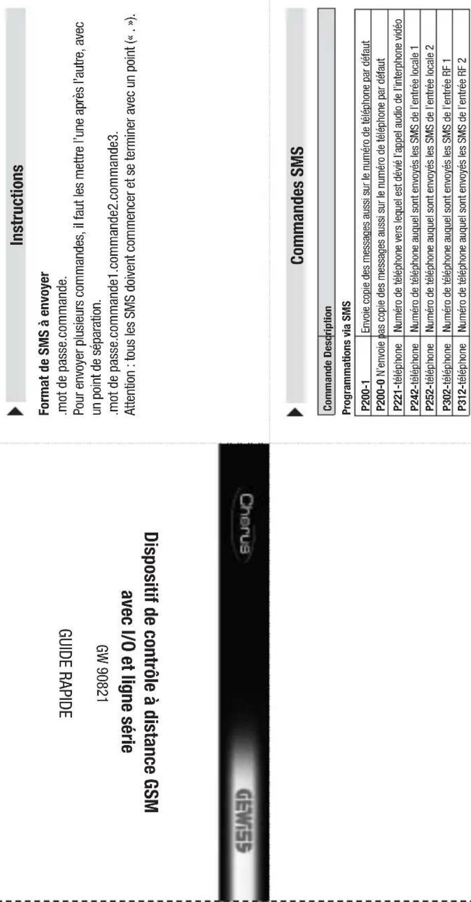
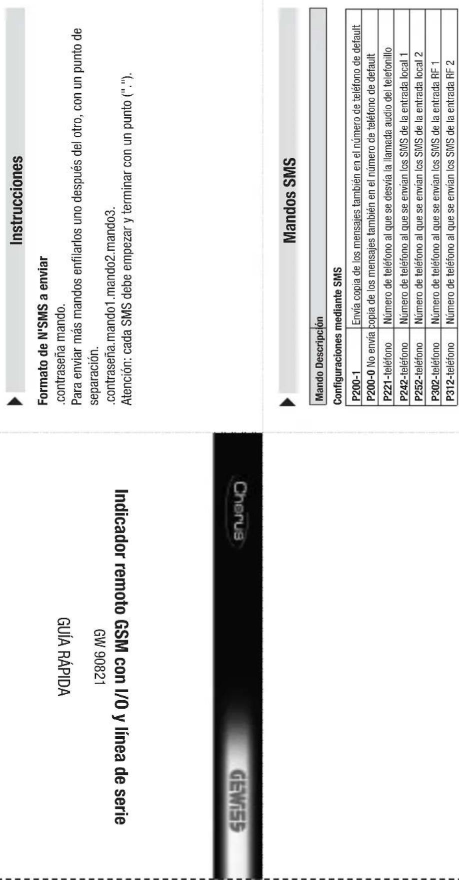
Structure of the SMS to be sent
password command.
To send more than one command, queue them one after another, separated by a full stop.
. password.Command1.Command2.Command3.
Warning: Each SMS must finish with a full stop (".")

SMS commands
Command Description
Configuration via SMS
| P200-1 | Send copy of messages also to the default phone number |
| P200-0 Do not send copy of messages also to the default phone number | |
| P221-telephone | Telephone number to which the intercom audio calls are forwarded |
| P242-telephone | Telephone number to which SMS are sent for local input 1 |
| P252-telephone | Telephone number to which SMS are sent for local input 2 |
| P302-telephone | Telephone number to which SMS are sent for RF input 1 |
| P312-telephone | Telephone number to which SMS are sent for RF input 2 |
Cut and fold this guide into four so you can always carry the most common commands with you at all times
Command Description
Local relay commands
CAL01-1 Activates relay output 1
CAL02-1Activates relay output 2
CAL02-0 Deactivates relay output 2 (and ends any timing in progress)
Electronicprogrammer serial commands
COP01-A Activates AUTO mode
C0B01-1 Activates MAN mode with output ON
COP01-0 Activates MAN mode with output OFF
(1) The final letter is a capital "0".
RF output commands
CAUTY-1 Activates IR-Telay output 1
CAR01-0 Deactivates RF relay output 1 (if the relay is configured as bistable)
CAR02-1 Activates RF relay output 2
CAR02-0 001_RF2:Deactivates Relay (only if the relay is configured as bistable)
CAR03-1 Activates RF relay output 3
CAR03-0 OUT_RF3:Deactivates relay (only if the relay is configured as bistable)
CAR04-1 Activates RF relay output 4
CAR04-0 OUT RF4: Deactivates relay (only if the relay is configured as bistable)
CAR05-1 Activates RF relay output 5
CAR05-0 OUT RF5:Deactivates relay (only if the relay is configured as bistable)
(1) The final letter is a capital "0".
(1) The final lette
Status requests
SGEO0-0 Status
SCF00-2 Status request for timer-thermostats and the electronic programmer
SGE00-3 Status request for burglar alarm system
| Command | Description |
| Timer-thermostat serial commands | |
| CCS01-H Set the function type: HEATING | |
| CCS01-C Sets the function type: CONDITIONING | |
| CCS01-0 (1) | Sets OFF mode |
| CCS01-A Sets AUTO mode | |
| CCS01-1 Sets MANUAL mode with T1 temperature | |
| CCS01-2 Sets MANUAL mode with T2 temperature | |
| CCS01-3 Sets MANUAL mode with T3 temperature | |
| CCS01-M-temperature | Sets MANUAL mode, specifying the temperature to be maintained, with resolution at 0,5° and commas as separators. E.g. 18,0 or 21,5. |
Commande Description
Commandes relais locales
Commandes sorties RF
CAR01-17 (2)
| Commande | Description |
- INSTALLAZIONE
- Inserimento SIM
- MAIUSCOLE E MINUSCOLE
- GENERAL DESCRIPTION
- INSTALLATION
- PROGRAMMING
- IN SERVICE
- TECHNICAL DATA 54
- GENERALWARNINGS
- Contents of the pack
- Summary
- Functions
- MANAGEABLE FUNCTIONS
- MESSAGESENT BY THE REPEATER
- Warnings for installation phase
- Verification of GSM signal cover
- SIM
- Assembly on the DIN Rail
- INSERTING THE BATTERIES
- CONNECTING THE INTERFACES
- Electrical connections
- Serial connections
- FLUSH-MOUNT TIMER-HERMOSTAT
- Installation tips
- Interface connections
- RF COMMAND AND CONTROL DEVICE INTERFACE
- SIM insertion
- Aerial position and connection
- Commissioning
- Configuration Procedures
- Password
- PC configuration
- CONNECTING THE PC TO THE REPEATER
- USING THE CONFIGURATION SOFTWARE
- Interaction and configuration via SMS
- UPPER CASE AND LOWER CASE
- STRUCTURE OF THE SMS SENT
- MULTIPLE COMMANDS
- CUSTOMISED TEXTS
- TELEPHONE NUMBERS
- Basic configuration
- Configuration via SMS
- GENERAL CONFIGURATION
- Final inspection
- Remote control via SMS
- Local indications
- Device status indicator LED
- GSM module status indicator LED
- Local commands
- Emergency blackout function
- Cleaning the repeater
- Replacing the batteries
- WARNING
- Recharging the SIM
- TECHNICAL DATA
- Default values
- BASIC OPTIONS
- SOMMAIRE
- AVERTISSEMENTS GENERAUX
- DESCRIPTION GENERALE
- CHRONOTHERMOSTAT ENCASTRABLE
- Insertion SIM
- COMMANDES POUR CHRONOTHERMOSTATS AVEC SÉRIE
- Structure of the SMS to be sent
- SMS commands
Brand : Gewiss
Model : GW90821
Category : Remote control device