
GW14767 - Electrical switch Gewiss - Free user manual and instructions
Find the device manual for free GW14767 Gewiss in PDF.
| Product Type | 1-channel 6 A Easy motor drive actuator for motorized shutters, curtains, and blinds |
| Brand | Gewiss |
| Model | GW14767 |
| Power Supply | KNX bus, 29 V DC SELV, max consumption 8 mA |
| Communication | KNX TP1 bus, 2-wire bus cable + shield |
| Relay Outputs | 2 NO 8 A (cosφ=1) at 250 V AC, max motor current 6 A (EN60669-2-1) |
| Control Elements | 1 programming button, 2 local control buttons |
| LED Indicators | 1 red programming LED, 2 green output status LEDs |
| Main Functions | Up/down control, alarm management (wind/rain), priority controls, scenarios (up to 8), slat adjustment (blind mode) |
| Dimensions | 2 Chorus modules (standard width ~36 mm) |
| Weight | Approx. 150 g (estimate) |
| Operating Temperature | -5 to 40 °C |
| Storage Temperature | -25 to 70 °C |
| Relative Humidity | Max 93 % (non-condensing) |
| Protection Rating | IP20 |
| Electrical Connections | Screw terminals, max cable cross-section 4 mm² |
| Bus Connection | 2-pin plug terminal ∅ 1 mm |
| Reference Standards | Low Voltage Directive 2006/95/EC, EMC 2004/108/EC, EN50428, EN50090-2-2 |
| Certifications | KNX |
| Maintenance and Cleaning | Use a dry cloth; no special maintenance required |
| Safety | Relay interlock to prevent motor damage; 4 mm separation between bus and power; installation by qualified personnel |
| General Information | Product from the Chorus series, indoor dry installation, Gewiss contact information available on request |
Frequently Asked Questions - GW14767 Gewiss
User questions about GW14767 Gewiss
0 question about this device. Answer the ones you know or ask your own.
Ask a new question about this device
Download the instructions for your Electrical switch in PDF format for free! Find your manual GW14767 - Gewiss and take your electronic device back in hand. On this page are published all the documents necessary for the use of your device. GW14767 by Gewiss.
USER MANUAL GW14767 Gewiss
natural_image
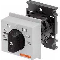
Close-up of a metallic electronic device with two square buttons and directional arrows, no visible text or symbols.GW 10 767 GW 12 767 GW 14 767
A
flowchart
graph TD
    A["Block 1"] --> B["Block 2"]
    C["Block 3"] --> D["Block 4"]
    style A fill:#f9f,stroke:#333
    style C fill:#f9f,stroke:#333
    style B fill:#ccf,stroke:#333
    style D fill:#ccf,stroke:#333
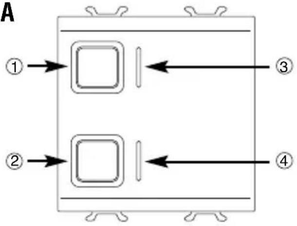
① Pulsante comando locale 1 (SU) - Local command button 1 (UP) - bouton de commande locale 1 (HAUT) - Pulsador mando local 1 (SUBIR) - Taste lokale Steuerung 1 (AUF)
② Pulsante comando locale 2 (GIÙ) - Local command button 2 (DOWN) - bouton de commande locale 2 (BAS) - Pulsador mando local 2 (BAJAR) - Taste lokale Steuerung 2 (AB)
③ LED stato uscita SU - LED output status UP - LED état de la sortie HAUT - 3 LED estado salida SUBIR - LED Status Ausgang AUF
④ LED stato uscita GIÙ - LED output status DOWN - LED état de la sortie BAS - LED estado salida BAJAR - LED Status Ausgang AB
⑤ LED di programmazione - Programming LED - LED de programmation - LED de programación - Programmier-LED
⑥ Tasto di programmazione - Programming key - Touche de programmation - Tecla de programación - Programmiertaste
B
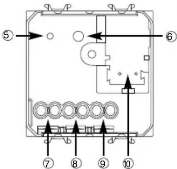
⑦ Uscita relè (GIÙ) - Output relay (DOWN) - Sortie relais (BAS) - Salida relé (BAJAR) - 7 Ausgang Relais (AB)
⑧ Uscita relè (SU) - Output relay (UP) - Sortie relais (HAUT) - Salida relé (SUBIR) - Ausgang Relais (AUF)
⑨ Comune - Common - Commun
Común - Allgemein
10 Terminali bus - Bus terminal - Borniers bus - Terminales bus - Busanschlüsse
INDICE
Warning! The safety of this appliance is only guaranteed if all the instructions given here are followed scrupulously. These should be read thoroughly and kept in a safe place.
Chorus products can be installed in environments which are dust-free and where no special protection against the penetration of water is required.
They shall be installed in compliance with the requirements for household devices set out by the national standards and rules applicable to low-voltage electrical installations which are in force in the country where the products are installed, or, when there are none, following the international standard for low-voltage electrical installations IEC 60364, or the European harmonization document HD 60364.
Gewiss sales organization is ready to provide full explanations and technical data on request.
Gewiss SpA reserves the right to make changes to the product described in this manual at any time and without giving any notice.
Pack content
n. 1 Easy 1 channel 6 A motor command actuator
n. 1 Bus terminal
n. 1 Cover with screw
n. 1 Installation and user manual
Summary
The Easy 1 channel 6 A motor command actuator controls the movement of motorised shutters, curtains and blinds. 2 output relays, one for UP and one for DOWN movements, are interlocked to avoid damage to the connected motor.
The movement commands can be accessed through Home Automation control or sensor devices using the KNX bus, or they can be generated locally using the two front buttons. The actuator is powered by the bus line and is fitted with 2 front green LEDs which indicate the shutter movement status (UP/DOWN).
The actuator can function in shutter or blind mode, and is capable of handling actuation following priority, scene and alarm commands. This device sends the bus information on the relay status (ON = contact closed, OFF = contact open) when it is switched on, on receiving a command and when it is activated manually.
The operating methods can be used simultaneously.
The actuator is fitted inside a standard flush-mounted box, in the space of two Chorus modules.
Functions
The motor actuator is able to handle movement, alarm and priority commands simultaneously. When more than one mode is activated at the same time, the actuator will enable the one with highest priority status.
The priority of the various functions, from maximum to minimum, is as follows:
- Relay status on loss of power to the bus
- Priority controls
- Alarms control
- Relay status on reinstatement of power to the bus
- Shutters/blinds movement, scene management
MAX PRIORITY
MIN PRIORITY
The two green status indicator LEDs light up when the contacts with the respective relays are closed.
SHUTTER MOVEMENT HANDLING
It raises or lowers the shutters, or stops the movement when it receives the relative command.
If the Stop command is not sent, the motor will only stop at the end of the Movement Time:
The shutters must therefore be fitted with stroke end sensors or an autonomous clutch.
BLIND MOVEMENT HANDLING

WARNING: In order to fully exploit this mode, the blinds must be able to mechanically orientate their laths with short UP/DOWN movements performed by the motor.
The blinds can be raised or lowered, or the movement can be stopped using the relative command. When a blind stops, the actuator receives a short movement command and the laths are rotated.
If the Stop command is not sent, the motor will only stop at the end of the Movement Time: the blinds must therefore be fitted with stroke end sensors or an autonomous clutch.
ALARMS CONTROL
If this function is enabled, the actuator completely opens or closes the shutters (blind, motorised curtain) when it receives an alarm message from a wind or rain sensor.
The open or close option is set during the programming phase.
As an extra safety measure, if the actuator does not receive a “no alarm” message for more than 30 minutes from the sensor, it interprets this as a malfunction and consequently moves the shutter to the preset safety position.
The alarm status persists until the actuator receives a “no alarm” message.
At the end of the alarm status, the actuator returns the shutter to its original position (or performs the last command received, if it received a command during the alarm status phase).
PERFORMING PRIORITY CONTROLS
On receiving an override command, it moves the shutter to the set position (UP or DOWN).
Until the priority control is cancelled, the actuator will ignore all other commands it receives, including wind or rain alarms.
When the priority control is cancelled, the actuator returns the shutter to its original position (or performs the last command received, if it received a command during the priority status phase).
SCENE MANAGEMENT
Each actuator channel is able to memorize and perform up to 8 scenes; each one is associated to a precise position (UP, DOWN or intermediate) of the shutter.
The scene can only be learned when the shutter is at a standstill.
Move the shutter to the desired position before memorising the scene.
INSTALLATION

WARNING: the installation of the device must be exclusively done by qualified personnel, following the regulations in force and the guidelines for KNX installations.
Warnings for KNX installations
- The length of the bus line between the actuator and the power supply unit must not exceed 350 metres.
- The length of the bus line between the actuator and the most distant KNX device must not exceed 700 metres.
- To avoid unwanted signals and overvoltages do not use ring circuits.
- Keep a distance of at least 4 mm between the individually insulated cables of the bus line and those of the electric line (figure C).
- Do not damage the electrical continuity conductor of the shielding (figure D).
WARNING: the unused bus signal cables and the electrical continuity conductor must never touch elements under power or the earth conductor!
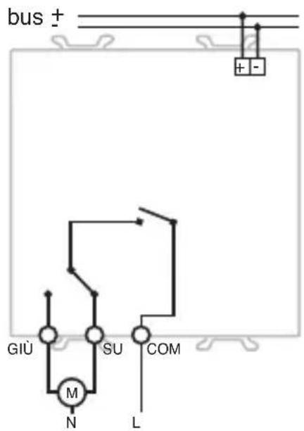
Electrical connections
WARNING: cut off mains power before connecting the device to the electricity mains!
Figure B shows the electrical connections diagram.
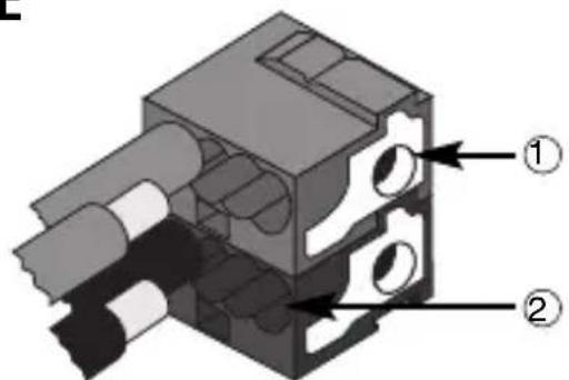
- Connect the bus cable's red wire to the terminal's red connector (+) and the black wire to the black connector (-). Up to 4 bus lines (wires of the same colour in the same connector) can be connected to the terminal (figure E).
- Insulate the screen, the electrical continuity conductor and the remaining white and yellow wires of the bus cable (should a bus cable with 4 conductors be used), which are not needed (figure D).
- Insert the bus connector into the special feet of the device. The fastener guides determine the direction it should be inserted. Insulate the bus terminal using the relative cover, which must be screwed onto the device.
The cover guarantees that the power cables and the bus cables are separated by at least 4 mm (figure F). - Connect the loads to the relative screw terminals on the back of the actuator (Figure G), checking that they do not exceed the current limits indicated in the Technical Specifications.
Initialization with the Easy Base Unit
- Power up the device through the bus.
- Have the system acquire the device with one of the following procedures:
• Automatic acquisition (the device still has the factory settings):
- select the “Application → New function” or “Application → Edit function” menu in the Easy base unit: the device will be recognized automatically.
- Manual acquisition (the factory settings have been modified):
- select the “Application →Search device” menu in the Easy base unit;
- briefly press (< 2 seconds) the programming key. The programming LED will light up during the acquisition process (figure A).
The device acquired by the Easy base unit will be listed, with the number assigned, in the channels of the “Application → New function” or “Application → Edit function” menus.
Initialization with the Easy Controller
- Power up the device through the bus.
- Have the system acquire the device with one of the following procedures:
• Automatic acquisition:
- select the "Search/Config." or "Scan Range" command in the "System" menu;
-
Manual acquisition:
-
select the "Add device" menu in the "System" menu;
- briefly press (< 2 seconds) the programming key. The programming LED will light up during the acquisition process (figure A).
The device acquired is listed with a number allocated, product code and a list of the channels in the "Devices" view.
Completing installation
Insert the devices into a Chorus support, making sure the two local command buttons are on the left.
Complete the installation with other Chorus devices or hole covers and fix it to the relative container (flush-mounted box, wall-mounted box etc). Apply the finish plate.
PROGRAMMING WITH THE EASY CONTROLLER
Programming the actuator through the Easy base unit (code GW 90 831) or with Easy Controller (GW90837 / GW90838 / GW90840).
The device can be selected by proceeding as follows:
- by pressing one of local command buttons: the corresponding channel will be highlighted in the channel list;
• directly from the list of channels.
The functions can be created after the device has been selected.
| Names of the functions | |
| blinds pushbutton Handling | of shutters or blinds using blinds pushbutton |
| blinds Handling of shutters | or blinds using blinds |
| Shutter edges Handling command for shutters or blinds with edges | |
| scene Actuation and memorising of the scenes | |
| priority control Override actuation | |
| Wind sensor Actuation with wind alarm | |
| Rain sensor Actuation with rain alarm | |
Refer to the Easy base unit or Easy Controller documentation for further information on the programming procedures.
PROGRAMMING WITH THE EASY BASE UNIT
Configuration parameters (Easy)
After creating the required function the actuator's operating parameters can be set from the "Application → Parameters" menu.
The parameters available, in relation to the function created, are listed in the following table.
The underlined value is the default value.
| Function: For all functions | |
| Parameter: Operation mode | |
| shutters Handling of Shutters | |
| blinds Handling of blinds and regulation of laths |
| Function: alarm | |
| Parameter: Alarm mode | |
| No alarm Alarm signal ignored | |
| Alarm pos.: DOWN Complete raising of the shutters | |
| Alarm pos.: UP Complete closure of the shutters |
Programming the stroke and movement times
The motor command actuator uses two settable time options to handle the transitional shutter positions and the power cut-off to the motor.
- Stroke time, which is the time required for the shutter to close entirely from a completely open position;
- Movement time, equal to 110% of the stroke time, which is the safety time after which the power to the electric motor is cut-off.
The stroke time is memorised on the actuator following the procedure below:
- Open the shutter completely ("all UP").
- At the same time hold down the 2 local command buttons (figure A): the LEDs will flash.
- Within 5 seconds (before the LEDs stop flashing) press the DOWN button and lower the shutter.
- When the shutter is completely closed ("all DOWN") press either of the local command buttons to memorise the stroke time then exit the setup procedure.
Make sure you press the button as soon as the shutter is completely closed in order to memorise the correct stroke time.
Using the local command buttons
The 2 local command buttons (figure A) are used to locally command the shutters or blinds as follows:
- Pressing and long holding (> 0.5 s) the button, it moves the shutter or blind UP (button 1) or DOWN (button 2) for the preset Movement Time.
- If the shutter or blind is moving, press and instantly release (<0.5 s) either button to stop it.
- In blind mode, when the blind is at a standstill, each time the button is pressed and instantly released (<0.5 s) will alter the inclination of the laths.
Transitional positions of the shutter or blind
When executing a scene, the shutter or blind will move to the previously memorised transitional position.
When an alarm or override status is cancelled (receipt of an alarm or override end command) the actuator will execute the last memorised command and, if there are none, it will move to the position before the alarm or override status occurred.
Behaviour on the failure and reinstatement of the bus power supply
If the power to the bus decreases below 18 V dc for over 1.5 ms the movement of the shutter or blind is interrupted
When the power is reinstated on the bus, the shutter or blind does not move until it receives a new movement command.
Maintenance
This device requires no maintenance. Use a dry cloth for possible cleaning.
TECHNICAL DATA
| Communication | Bus KNX |
| Power Supply | By KNX, 29 V dc SELV bus |
| Bus cable | KNX TP1 |
| Bus current consumption | 8 mA max |
| Control elements | 1 mini programming key |
| 2 local command buttons | |
| Display elements | 1 red programming LED |
| 2 green output status signal LEDs | |
| Actuator elements | 1 single-pole relay with phase branch circuit |
| 1 single-pole relay with exchange contact and phase branch circuit | |
| Output contact | 2 NO 8 A (cosφ=1) - 250 V ac |
| Max current per load type | Motors and reduction units: 6A according to EN60669-2-1Resistive load: 8 A |
| Ambit of use | Indoors, dry places |
| Operating temperature | -5 ÷ 40 °C |
| Storage temperature | -25 ÷ 70 °C |
| Relative humidity | Max 93% (no condensation) |
| Bus connection | 2-pin ∅ 1 mm plug connector |
| Electrical connections | Screw terminals, Max cable width: 4 mm2 |
| Protection rating | IP20 |
| Dimensions | 2 Chorus modules |
| Reference standards | Low Voltage Directive 2006/95/ECElectromagnetic Compatibility Standard 2004/108/ECEN50428,EN50090-2-2 |
| Certification | KNX |
SOMMAIRE
page AVERTISSEMENTS GENERAUX 28
DESCRIPTION GENERALE 29
INSTALLATION 31
PROGRAMMATION AVEC EASY CONTROLLER 32
EN SERVICE 36
MOUVEMENTS DES VOLETS
① Cavo bus - Bus cable - Câble bus - Cable bus - Buskabel
② Conduitore di continuità elettrica - Electrical continuity conductor - Conducteur de continuité électrique - Conductor de continuidad eléctrica - Stromdurchgangsleiter
③ Schermatura - Shielding - Blindage - Blindaje - Abschirmung
E
natural_image
Technical illustration of a mechanical assembly with multiple circular components and a tool (no text or symbols visible)According to article 9 paragraph 2 of the European Directive 2004/108/EC and to article R2 paragraph 6 of the Decision 768/2008/EC, the responsible for placing the apparatus on the Community market is:
GEWISS S.p.A Via A. Volta, 1 - 24069 Cenate Sotto (BG) Italy Tel: +39 035 946 111 Fax: +39 035 945 270 E-mail: qualitymarks@gewiss.com


+39 035 946 111
8.30 - 12.30 / 14.00 - 18.00 lunedì ÷ venerdì - monday ÷ friday

+39 035 946 260

- INDICE
- Pack content
- Summary
- Functions
- SHUTTER MOVEMENT HANDLING
- BLIND MOVEMENT HANDLING
- ALARMS CONTROL
- PERFORMING PRIORITY CONTROLS
- SCENE MANAGEMENT
- INSTALLATION
- Warnings for KNX installations
- Electrical connections
- Initialization with the Easy Base Unit
- Initialization with the Easy Controller
- Completing installation
- PROGRAMMING WITH THE EASY CONTROLLER
- PROGRAMMING WITH THE EASY BASE UNIT
- Configuration parameters (Easy)
- Programming the stroke and movement times
- Using the local command buttons
- Transitional positions of the shutter or blind
- Behaviour on the failure and reinstatement of the bus power supply
- Maintenance
- TECHNICAL DATA
- SOMMAIRE
- MOUVEMENTS DES VOLETS
Brand : Gewiss
Model : GW14767
Category : Electrical switch