
SRDVRLB - VCR Tripp Lite - Free user manual and instructions
Find the device manual for free SRDVRLB Tripp Lite in PDF.

| Product Type | DVR Security Cabinet 6U |
| Brand | Tripp Lite |
| Model | SRDVRLB |
| Height (U) | 6U (approx. 266.7 mm) |
| Mounting Width | 19 inches (482.6 mm) |
| Adjustable Depth | 25 mm to 412 mm |
| Maximum Load Capacity | 27 kg (60 lbs) |
| Material | Steel (unspecified, typically steel) |
| Color | Black (assumed) |
| Lockable Door | Yes, with included keys |
| Cooling Fan | Yes, with air filter |
| Wall Mounting | Yes, via keyhole slots and brackets |
| Table/Floor Mounting | Yes, via bottom holes |
| Adjustable Mounting Rails | Yes, adjustable depth |
| Cable Management | Access holes at rear and bottom |
| Removable Top Panel | Yes |
| Warranty | 5-year limited |
| Included Parts | Keys, cage nuts, mounting screws, crossbrace |
| Operating Temperature | Controlled indoor environment |
| Humidity | Avoid extreme humidity |
| Cleaning | Dry cloth, avoid liquids |
Frequently Asked Questions - SRDVRLB Tripp Lite
User questions about SRDVRLB Tripp Lite
0 question about this device. Answer the ones you know or ask your own.
Ask a new question about this device
Download the instructions for your VCR in PDF format for free! Find your manual SRDVRLB - Tripp Lite and take your electronic device back in hand. On this page are published all the documents necessary for the use of your device. SRDVRLB by Tripp Lite.
USER MANUAL SRDVRLB Tripp Lite
- Important Safety Instructions 2
- Overview 2
- Feature Identification 3
-
Enclosure Installation 4
4.1 Preparation 4
4.2 Unpacking 4 -
Enclosure Configuration 5
5.1 Door Locks 5
5.2 Cable Access and Management 5
5.3 Mounting Rails 5
5.4 Adjusting Mounting Rail Depth 6
- Mounting the Enclosure 6
6.1 Wall Mounting 6
6.2 Tabletop/Floor Mounting 7 - Equipment Installation 8
7.1 Installing or Removing Cage Nuts 8 - Storage and Service 9
- Warranty and Product Registration 9
Español 10
Français 19
PROTECT YOUR INVESTMENT!
Register your product for quicker service and ultimate peace of mind.
You could also win an ISOBAR6ULTRA surge protector—a \$50 value!
www.tripplite.com/warranty


Manufacturing Excellence.
1. Important Safety Instructions
SAVE THESE INSTRUCTIONS
This manual contains instructions and warnings that must be followed during the installation and operation of the product described in this manual.
Failure to comply may invalidate the warranty and cause property damage or personal injury.
- Keep the enclosure in a controlled indoor environment, away from moisture, temperature extremes, flammable liquids and gasses, conductive contaminants, dust and direct sunlight.
- Leave adequate space at the front and rear of the enclosure for proper ventilation. Do not block, cover or insert objects into the external ventilation openings of the enclosure.
- The enclosure is extremely heavy. Use caution when handling the enclosure. Do not attempt to unpack, move or install it unassisted. Use a mechanical device such as a forklift or pallet jack to move the enclosure in the shipping container.
- Do not place any object on the enclosure, especially containers of liquid, and do not attempt to stack the enclosures.
- Inspect the shipping container and the enclosure for shipping damage. Do not use the enclosure if it is damaged.
- Leave the enclosure in the shipping container until it has been moved as close to the final installation location as possible.
• Install the enclosure in a structurally sound area capable of handling the load, or on a level floor that is able to bear the weight of the enclosure, all equipment that will be installed in the enclosure and any other enclosures and/or equipment that will be installed nearby. - For permanent wall mounting, be sure to securely fasten the enclosure to the building structure before operation.
- Use caution when cutting packing materials. The enclosure could be scratched, causing damage not covered by the warranty.
- Save all packing materials for later use. Repacking and shipping the enclosure without the original packing materials may cause product damage that will void the warranty.
- Use of this equipment in life support applications where failure of this equipment can reasonably be expected to cause the failure of the life support equipment or to significantly affect its safety or effectiveness is not recommended. Do not use this equipment in the presence of a flammable anesthetic mixture with air, oxygen or nitrous oxide.
2. Overview
Your Security DVR Lockbox Enclosure is an all-in-one solution for securely storing and cooling a digital video recorder (DVR) device. Using a compact 6U housing, this unit can be conveniently mounted to walls as well as be configured for tabletop or floor placement. To prevent theft and device tampering, the SRDVRLB model comes equipped with a locking door that overlaps the enclosure's top panel and sides. For optimal system performance, a pre-installed cooling fan with air filter increases cool airflow inside and restricts incoming dust and airborne particulates.
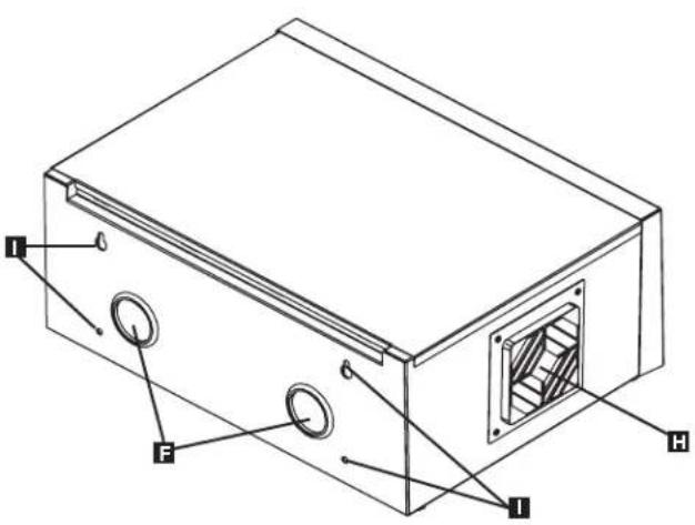
3. Feature Identification
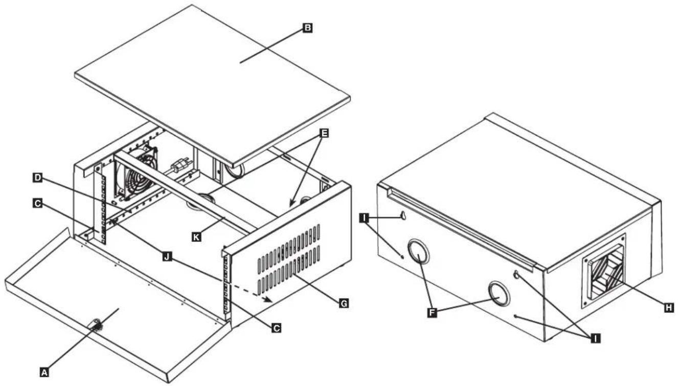
A Locking Front Door
B Removable Top Panel
Vertical Mounting Rails
D Horizontal Rails
E Bottom Cable Access Holes
F Rear Cable Access Holes
G Vent
H Cooling Fan with Air Filter
Mounting Keyholes and Support Mounting Holes
J Bottom Mounting Holes
K Removable Cross Support Brace (Used for Wall Mounting the Enclosure)
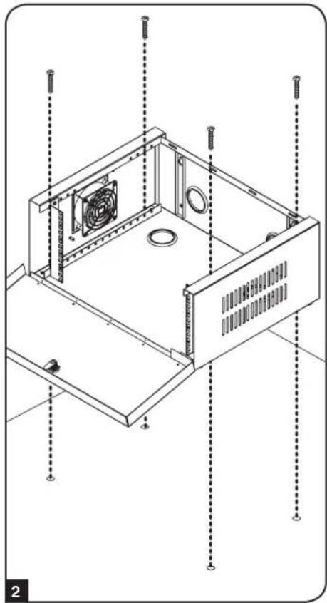
4. Enclosure Installation

Caution! Read All Instructions and Warnings Before Installation!

Warning: Rack enclosures can be extremely heavy. Do not attempt to unpack, move or install the enclosure without assistance. Use extreme caution when handling the enclosure and be sure to follow all handling and installation instructions. Do not attempt to install equipment without first stabilizing the enclosure.
4.1 Preparation
The enclosure must be installed in a structually sound area that is able to bear the weight of the enclosure, all the equipment that will be installed in the enclosure and any other enclosures and/or equipment that will be installed nearby. Before unpacking the enclosure, you should transport the shipping container closer to the final installation location to minimize the distance you will need to move the unit after the protective packaging has been removed. If you plan to store the enclosure for an extended period before installation, follow the instructions in the Storage and Service section.
You need the following tools:
- Level
• Phillips-head Screwdriver - Appropriate tools for wall mounting
You also need the following hardware:
- Appropriate hardware for wall mounting or tabletop/floor mounting (not included)
4.2 Unpacking

Use at least two people to unpack the enclosure.
1 Move shipping pallet to a firm, level surface.
2 Open box and remove the four foam corner protectors. Save all packing materials for later use unless you are certain they will not be required. Packing materials are recyclable.
3 With one person on each side, carefully lift the enclosure out of the box and place on a firm, level surface.
4 Examine the enclosure for any damage or loose parts. Confirm all parts are present. If anything is missing or damaged, contact Tripp Lite for assistance. Do not attempt to use the enclosure if it has been damaged.

Never extend more than one component from the enclosure at a time.


Warning: Never attempt to lift or install without adequate help. Do not try lifting the enclosure alone.
5. Enclosure Configuration
Before installation, plan the location and arrangement of components within the enclosure. Make sure all mounting rails are reversed or adjusted for depth, depending on your equipment configuration.
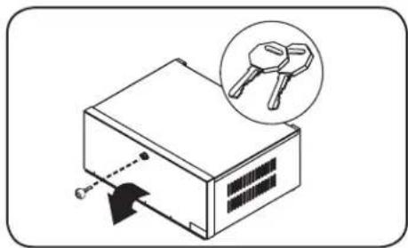
5.1 Door Locks
The front door contains a lock that is accessible with the included keys.
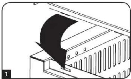
1 Before attempting to close and lock the front door, first ensure that the top panel's notches are secured within the rear panel slots. Then gently place the top panel over the enclosure frame.
2 Once the top panel is secured, swing the front door up. The front door will overlap the top panel and the enclosure's left and right sides. Use an included key to lock the door.
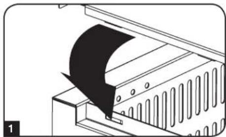
5.2 Cable Access and Management
The rear and bottom of the enclosure has two circular holes per side for cable access and management. To uncover a cable access hole, simply pop out the desired cap.
natural_image
Diagram of a device with a magnified inset showing two key holders (no text or symbols present)
natural_image
Diagram of a mechanical device with a curved black component inserted, showing internal structure (no text or symbols)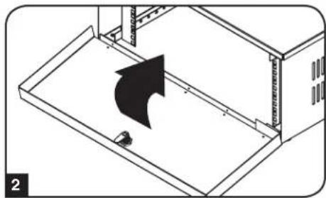
natural_image
Isometric diagram of a device with an arrow indicating direction, no text or symbols present
natural_image
Diagram of a mechanical assembly with arrows indicating direction of movement, no text or symbols present5.3 Mounting Rails
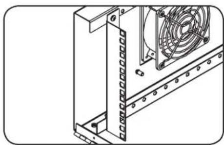
The enclosure comes with mounting rails with square holes for 19" rackmount-compatible DVR equipment. To install your DVR, use the included cage nuts and other device hardware (see 7.1 Installing or Removing Cage Nuts section for more information). Warning: Be sure to have the enclosure securely mounted to the wall, tabletop or floor before mounting any equipment inside. Also be sure to have all the right adjustments on your rails before mounting equipment (see Adjusting Mounting Rail Depth section for more information).
natural_image
Technical line drawing of a mechanical assembly with a fan and mounting bracket (no text or symbols)5. Enclosure Configuration continued
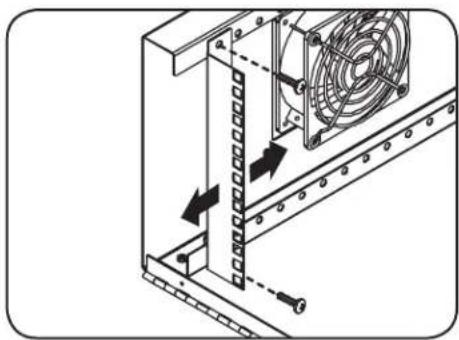
5.4 Adjusting Mounting Rail Depth
Warning: Do not attempt to adjust rails while equipment is installed in the enclosure. Do not attempt to use rails without screws installed (two per rail).
The two mounting rails are pre-installed to accommodate equipment with a mounting depth of 16.25 inches (412 mm). Do not adjust the mounting rails unless your equipment requires a different mounting depth. The front and rear sets of rails can be adjusted independently in 1-inch (25 mm) increments for mounting depths between 1 inch (25 mm) and 16 inches (406 mm).
1 Each rail is connected to the enclosure with two screws: one in the upper corner and another in the lower corner. Using a Phillips-head screwdriver, remove the screws that fasten the rails to the enclosure.
2 Slide the mounting rails to the desired depth and reattach them using the screws you removed in Step 1.
natural_image
Technical diagram of a server rack with a fan and cooling mechanism, showing directional arrows (no text or symbols)6. Mounting the Enclosure
6.1 Wall Mounting
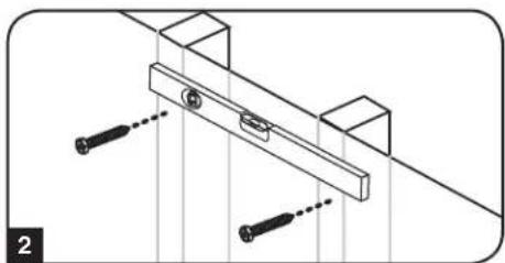
Warning: The enclosure supports 60 lb. (27 kg) of total equipment weight. Install the cross support brace inside the enclosure for heavy equipment installations. Do not attempt to mount the enclosure to the wall with equipment in the enclosure.
Note: Enclosure must be installed by a qualified technician. Before mounting, use a level and tape measure to position your mounting area precisely. Use appropriate fasteners (not included) to secure the enclosure to the wall. Use suitable mounting means when installing to cinder block, concrete, drywall or wood studs. Warning: The supporting surface must be able to safely support the combined load of the equipment and all attached hardware and components.
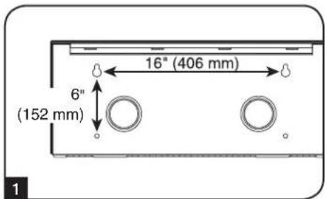
1 There are two keyhole slots and two support mounting holes on the back of the enclosure. Each keyhole can accommodate an M8 or 5/16" bolt. The holes are spaced 16" (406 mm) apart horizontally and 5.9" (150 mm) apart vertically, as shown in the diagram.
Note: The below wall-mounting instructions and diagrams are for mounting into wood studs. For solid or hollow wall-mounting, first check that any anchors used are capable of supporting the weight of the enclosure and its contents.
2 Using a tape measure and level, identify the wall location you want to position your enclosure and mark two mounting holes 16" (406 mm) apart. Then insert two M8 or 5/16" bolts into the mounting hole markings. Upon inserting the hardware, make sure to leave a 1/8" (3.18 mm) space between the bolt head and the wall.
3 With the help of an assistant or mechanical lifting device, hang the enclosure's keyholes onto the bolts attached to the wall. The keyholes will fit over the bolts and the enclosure should slide down until secure. Tighten the bolts once it is determined that the enclosure is safely supported.
4 Secure the enclosure to the wall by fastening two user-supplied M8 or 5/16" bolts through the support mounting holes.
natural_image
Technical line drawing of a mechanical clamp or bracket assembly with two screws inserted (no text or symbols)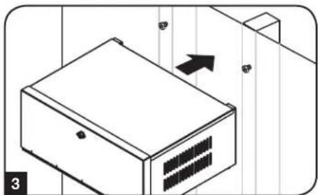
natural_image
Isometric line drawing of a server rack with ventilation slots and an arrow indicating direction (no text or symbols)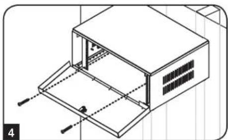
natural_image
Isometric line drawing of a two-story building with ventilation grilles and support beams (no text or symbols)6. Mounting the Enclosure continued
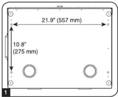
6.2 Tabletop/Floor Mounting
1 There are four mounting holes on the bottom of the enclosure. Each hole can accommodate an M8 or 5/16" bolt. The holes are spaced 21.9" (557 mm) apart horizontally and 10.8" (275 mm) apart vertically, as shown in the diagram.
2 Using a tape measure, identify the tabletop or floor location where you want to position your enclosure and mark two mounting holes 21.9" (557 mm) apart horizontally and 10.8" (275 mm) apart vertically. Remove the enclosure's top panel. Then align the enclosure with the marking holes and secure the enclosure using four M8 or 5/16" bolts. Note: Depending on surface, pilot holes may need to be drilled prior to hardware installation.
natural_image
Isometric technical drawing of a mechanical housing with ventilation grilles and mounting holes (no text or symbols)7. Equipment Installation
Warning: Do not install equipment until you have stabilized the enclosure. Install heavier equipment first and install it towards the bottom of the enclosure. Install equipment starting from the bottom of the enclosure and proceeding toward the top of the enclosure - never the reverse. If using sliding equipment rails, be careful when extending the rails. Do not extend more than one set of sliding equipment rails at one time. Avoid extending sliding equipment rails near the top of the enclosure.
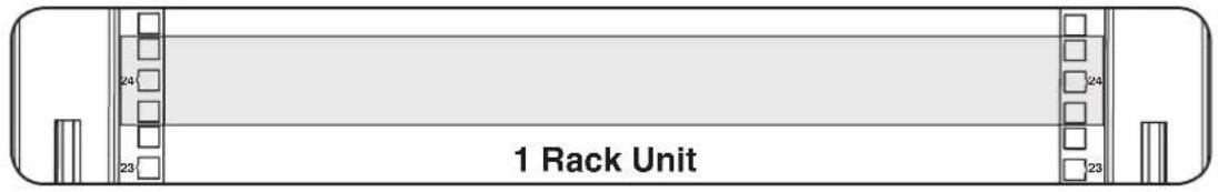
Note: The square holes in the middle of each rack unit are numbered and also include a small notch to aid identification. A single rack unit includes the space occupied by the numbered hole and the holes directly above and below.
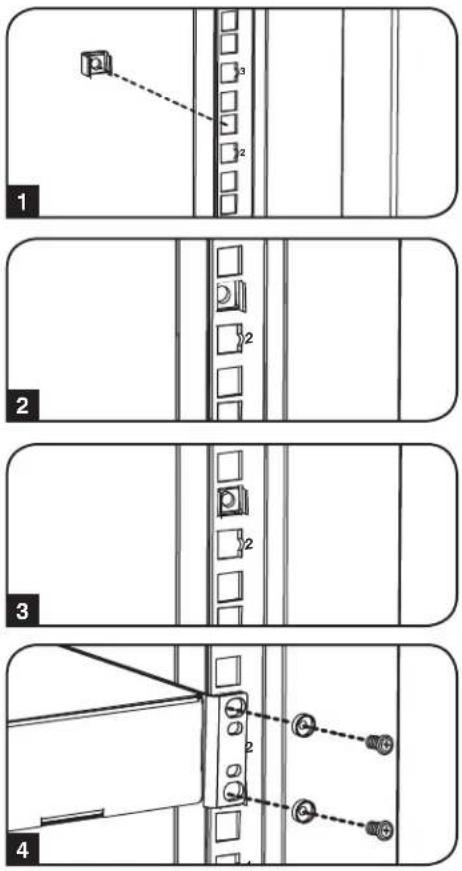
7.1 Installing or Removing Cage Nuts
WARNING: The flanges of the cage nuts should engage the sides of the square opening in the rail, not the top and bottom. Follow the instructions in your equipment documentation to ensure proper installation.
1 Locate the numbered square openings in the mounting rails where you plan to install your equipment. You will install cage nuts (included) into the square openings in order to provide an attachment point for the mounting screws (included). Note: Consult your equipment documentation to determine how many cage nuts will be required and where they will need to be installed.
2 From the inside of the mounting rail, insert one of the flanges of the cage nut through the square opening. Press it against the side of the square opening. Each flange should engage one side of the square opening, not the top or bottom.
3 Compress the cage nut at the sides slightly to allow the remaining flange to fit through the square opening. When the cage nut is properly installed, both flanges will protrude through the square opening and will be visible on the outer surface of the mounting rail. Repeat steps 1-3 until all required cage nuts are installed.
4 After installing the required cage nuts, use the included black mounting screws and cup washers to secure your equipment to the rack rail. Place the cup washers between the screws and the equipment mounting brackets.
Note: Your equipment may also include mounting hardware. Read the mounting instructions that came with your equipment before installing your equipment.
To Remove Cage Nuts, Reverse Steps 1-3
Note: You may wish to use a cage nut tool (user-supplied) to aid cage nut installation and removal.
8. Storage and Service
Storage
The enclosure should be stored in a controlled indoor environment, away from moisture, temperature extremes, flammable liquids and gasses, conductive contaminants, dust and direct sunlight. Store the enclosure in its original shipping container if possible.
Service
The enclosure is covered by the limited warranty described in this manual. For more information, visit www.tripplite.com/support.
9. Warranty and Product Registration
5-Year Limited Warranty
Seller warrants this product, if used in accordance with all applicable instructions, to be free from original defects in material and workmanship for a period of 5 years from the date of initial purchase. If the product should prove defective in material or workmanship within that period, Seller will repair or replace the product, at its sole discretion.
THIS WARRANTY DOES NOT APPLY TO NORMAL WEAR OR TO DAMAGE RESULTING FROM ACCIDENT, MISUSE, ABUSE OR NEGLECT. SELLER MAKES NO EXPRESS WARRANTIES OTHER THAN THE WARRANTY EXPRESSLY SET FORTH HEREIN. EXCEPT TO THE EXTENT PROHIBITED BY APPLICABLE LAW, ALL IMPLIED WARRANTIES, INCLUDING ALL WARRANTIES OF MERCHANTABILITY OR FITNESS, ARE LIMITED IN DURATION TO THE WARRANTY PERIOD SET FORTH ABOVE; AND THIS WARRANTY EXPRESSLY EXCLUDES ALL INCIDENTAL AND CONSEQUENTIAL DAMAGES. (Some states do not allow limitations on how long an implied warranty lasts, and some states do not allow the exclusion or limitation of incidental or consequential damages, so the above limitations or exclusions may not apply to you. This warranty gives you specific legal rights, and you may have other rights which vary from jurisdiction to jurisdiction).
WARNING: The individual user should take care to determine prior to use whether this device is suitable, adequate or safe for the use intended. Since individual applications are subject to great variation, the manufacturer makes no representation or warranty as to the suitability or fitness of these devices for any specific application.
Product Registration
Visit www.triplite.com/warranty today to register your new Tripp Lite product. You'll be automatically entered into a drawing for a chance to win a FREE Tripp Lite product!*
* No purchase necessary. Void where prohibited. Some restrictions apply. See website for details.
Tripp Lite has a policy of continuous improvement. Specifications are subject to change without notice.


1111 W. 35th Street, Chicago, IL 60609 USA • www.tripplite.com/support
1111 W. 35th Street, Chicago, IL 60609 USA • www.tripplite.com/support
natural_image
Diagram of a mechanical device with a curved black component inserted, showing internal structure (no text or symbols)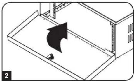
natural_image
Diagram of a device with an arrow indicating direction, showing a closed panel and a small bird (no text or symbols present)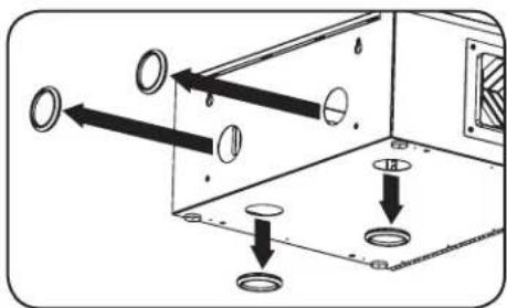
natural_image
Technical line drawing of a mechanical assembly with a fan and mounting bracket (no text or symbols)natural_image
Technical line drawing of a mechanical clamp or bracket assembly with two screws inserted (no text or symbols)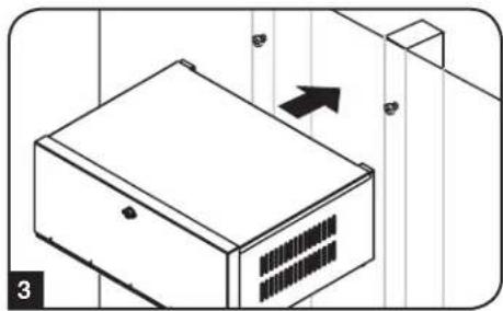
natural_image
Isometric line drawing of a server rack with ventilation slots and a directional arrow (no text or symbols)
natural_image
Isometric line drawing of a two-story building with ventilation grilles and structural beams (no text or symbols)natural_image
Isometric technical drawing of a mechanical housing with ventilation slots and mounting holes (no text or symbols)1111 W. 35th Street, Chicago, IL 60609 USA • www.tripplite.com/support
Manufacturing Excellence.
natural_image
Diagram of a mechanical device with a curved black component inserted, showing internal structure (no text or symbols)
natural_image
Isometric diagram of a device with an arrow indicating direction, no text or symbols presentnatural_image
Diagram of a mechanical assembly with arrows indicating direction of movement, no text or symbols presentnatural_image
Technical line drawing of a mechanical assembly with a fan and mounting bracket (no text or symbols)natural_image
Technical diagram of a mechanical assembly with arrows indicating motion or force direction (no text or symbols)natural_image
Technical line drawing of a mechanical assembly with two screws and a bracket (no text or symbols)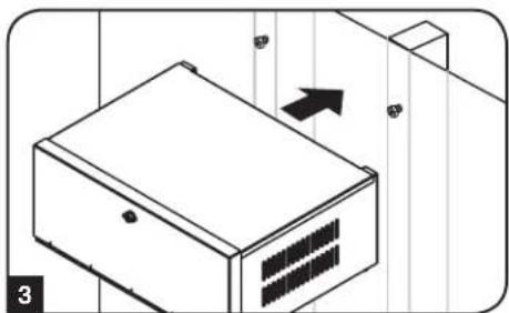
natural_image
Isometric line drawing of a server rack with ventilation slots and an arrow indicating direction (no text or symbols)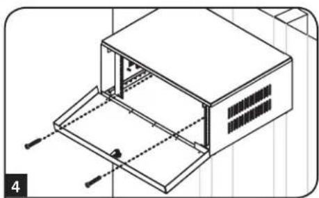
natural_image
Isometric line drawing of a two-tiered storage unit with mounting holes and ventilation slots (no text or symbols)natural_image
Isometric technical drawing of a computer case with ventilation duct and mounting hardware (no text or symbols)1111 W. 35th Street, Chicago, IL 60609 USA • www.tripplite.com/support
- PROTECT YOUR INVESTMENT!
- Important Safety Instructions
- SAVE THESE INSTRUCTIONS
- Overview
- Feature Identification
- Enclosure Installation
- Caution! Read All Instructions and Warnings Before Installation!
- Preparation
- Unpacking
- Use at least two people to unpack the enclosure.
- Never extend more than one component from the enclosure at a time.
- Warning: Never attempt to lift or install without adequate help. Do not try lifting the enclosure alone.
- Enclosure Configuration
- Door Locks
- Cable Access and Management
- Mounting Rails
- Enclosure Configuration continued
- Adjusting Mounting Rail Depth
- Mounting the Enclosure
- Wall Mounting
- Mounting the Enclosure continued
- Tabletop/Floor Mounting
- Equipment Installation
- Installing or Removing Cage Nuts
- To Remove Cage Nuts, Reverse Steps 1-3
- Storage and Service
- Storage
- Service
- Warranty and Product Registration
- 5-Year Limited Warranty
- Product Registration
Brand : Tripp Lite
Model : SRDVRLB
Category : VCR