
VTSSC72 - Welding machine VELLEMAN - Free user manual and instructions
Find the device manual for free VTSSC72 VELLEMAN in PDF.
| Product type | Soldering station |
| Brand | VELLEMAN |
| Model | VTSSC72 |
| Max. heating element power | 80 W |
| Temperature range | 200 - 480 °C (392 - 896 °F) |
| Temperature stability | ± 3 °C (± 6 °F) |
| Soldering iron voltage | 32 V AC |
| Display | Digital LCD with °C or °F scale |
| Heating element | Ceramic with integrated temperature sensor |
| Temperature adjustment | Electronic, with password lock |
| Protection | Against voltage spikes and current surges (zero-cross connection) |
| Isolated power supply | High-quality 32 VAC transformer |
| Fault detection | Sensor (S--E) and heating element (H--E): automatic shutdown |
| Dimensions | 185 x 100 x 170 mm |
| Weight | 1.58 kg |
| Contents | Soldering station, soldering iron, stand with steel wool |
| Replacement tips | 0.4 mm (BITC03), 0.8 mm (BITC201) |
| Replacement iron | VTSSC7/SP1 |
| Tip maintenance | Clean with wet sponge or isopropyl alcohol, do not use files |
| Warranty (consumer) | 24 months against manufacturing defects |
Frequently Asked Questions - VTSSC72 VELLEMAN
User questions about VTSSC72 VELLEMAN
0 question about this device. Answer the ones you know or ask your own.
Ask a new question about this device
Download the instructions for your Welding machine in PDF format for free! Find your manual VTSSC72 - VELLEMAN and take your electronic device back in hand. On this page are published all the documents necessary for the use of your device. VTSSC72 by VELLEMAN.
USER MANUAL VTSSC72 VELLEMAN
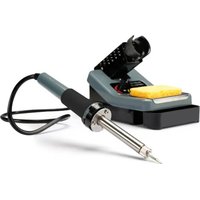
SOLDERING STATION 80W/230V
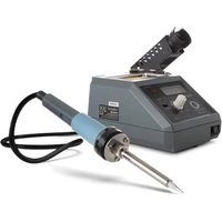
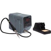
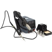
natural_image
Exterior view of a soldering machine (LF-1600) and a soldering kit with solder pad, both without visible text or symbols.USER MANUAL 3
GEBRUIKERSHAND LEIDING 7
NOTICE D'EMPLOI 11
MANUAL DEL USUARIO 16
To all residents of the European Union
Important environmental information about this product

This symbol on the device or the package indicates that disposal of the device after its lifecycle could harm the environment.
Do not dispose of the unit (or batteries) as unsorted municipal waste; it should be taken to a specialized company for recycling.
This device should be returned to your distributor or to a local recycling service.
Respect the local environmental rules.
If in doubt, contact your local waste disposal authorities.
Thank you for choosing Velleman! Please read the manual thoroughly before bringing this device into service. If the device was damaged in transit, don't install or use it and contact your dealer.
The VTSSC70 comes with:
1x soldering station + power cord
1x soldering iron + tip and stand with tip cleaner
2. Safety Instructions
 | Keep this device away from children and unauthorized users. | |
 | Do not use near inflammable products or in explosive atmospheres. Only use in properly ventilated rooms. | |
 | Do not touch the shaft or solde ring tip as this can cause serio us burns. Always return the soldering iron to its stand between uses; always let it cool down after use and before storage.Incorrect use may cause fire. | |
 | Always disconnect mains power when the device is not in use or when maintenance activities are performed. Handle the power cord by the plug only. Do not crimp the power cord(s) and protect against damage. Have an authorised dealer replace it if necessary. | |
 |  | Do not inhale solder fumes. Dispose of solder residue in accordance with local regulations. |
 | Never use the device on live electronic circuits. Make sure power to the work piece is cut and capacitors are discharged. | |
3. General Guidelines
Refer to the Velleman® Service and Quality Warranty on the last pages of this manual.
 | Indoor use only. Keep this device away form rain, moisture, splashing and dripping liquids. Never put object filled with liquid on top. |
 | Keep this device away from dust and extreme heat. Make sure the ventilation openings are clear at all times. |
 | Protected this device from shocks and abuse. Avoid brute force when operating the device. |
- Familiarise yourself with the functions of the device before actually using it.
- All modifications of the device are forbidden for safety reasons. Damage caused by user modifications to the device is not covered by the warranty.
- Only use the device for its intended purpose. Using the device in an unauthorised way will void the warranty.
- Dama ge caused by disregard of certain guidelines in this manual i s not covered by the warranty and the cealer will not accept responsibility for any ensuing defects or problems.
- Do not switch the device on immediately after it has been exposed to changes in temperature. Protect the device against damage by leaving it switched off until it has reached room temperature.
VTSSC70
4. Features
• electronic temperature control
- password lock
- sensor and heater fail notification
- LCD display with digital temperature scale (°C or °F)
- with on/off switch
• ceramic heating element with temperature sensor
- HEATER/SENSOR FAILED DETECTION: if the sensor circuit fails, the display reads "S--E" and heater power is cut. If heater circuit fails the display will read "H--E" and heater power is cut.
- TEMPERATUE "LOCK-OUT" FEATURE: the temperature can be locked with a password which might be useful in a production line.
- ESD SAFE AND SPIKE FREE CIRCUITRY: the "Zero Voltage" electronic switching design also protects voltage and current sensitive components (CMOS devices, etc.) against overcurrent and transient voltage spikes.
- LIGHTWEIGHT SOLDERING IRON: ergonomic mini handle that stays cool and prevents operator fatigue.
• isolated power supply: high-quality 32Vac transformer designed for lead-free soldering
• temperature stability: tip temperature accurate to within ±3^ ( 6^ )
• available options:
- spare soldering bits: 0.4mm (BITC03), 0.8mm (BITC201)
o spare soldering iron: VTSSC7/SP1
5. Overview
Refer to the illustrations on page 2 of this manual.
| VTSSC70 | 5 | soldering | |
| 1 | display 6 power switch | ||
| 2 | SET-button 7 power connecto | r | |
| 3 | down-button (▼) | 8 | fuse |
| 4 | up-button (▲) | 9 | earth jack |
| display | B | tempera | |
| A | temperature indication | C | heating indication |
6. Description
- This soldering station is designed to meet the present and future needs of the electronic production industry. The VTSSC70 is engineered to meet the stringent demands of hobbyists, maintenance personnel and production people alike.
- A high-quality sensor and heat transfer technology ensure precise temperature regulation which is essential for making consistent, reliable soldered connections.
- The aluminium alloy housing has several advantages: strong, good heat sink and very resistant to electro-magnetic interference.
- The VTSSC70s' electronic circuitry enables the user to set soldering temperatures between 200 and 480°C (392 to 896°F) without having to replace the tip or the heating element. The temperature is maintained to within ± 3°C (± 6°F) of the normal operating temperature by a thermocouple sensor placed in the head of the heating element. The 80W power results in a rapid heat-up and fast recovery.
- The revolutionary "zero voltage" switching design also protects voltage- and current-sensitive components (CMOS devices, etc.) against the damaging current and transient voltage spikes commonly produced by less efficient, mechanically switched stations. The heating elements are galvanically isolated from the electrical supply by an isolating transformer that prevents the system from using a max. tension higher than a (safe) 32VAC.
VTSSC70
7. Operating Temperature
The most common soldering alloys used in the electronics industry consist of 60% tin and 40% lead. The operating temperature of this type of solder is detailed below and can vary from manufacturer to manufacturer. However, to meet RoHS requirements, these solders are no longer allowed and are replaced by lead-free solders that require a working temperature which is ±30^ C (54°F) higher.
| leaded r | lead-free solde | |
| Melting point 215°C (419°F) | 220°C (428°F) | |
| Normal Operation 270-320°C (518-608°F) | 300-360°C (572-680°F) | |
| Production Line Operation 320-380°C (608-716°F) | 360-410°C (680-770°F) |
A good joint is assured if the iron's operating temperature is set within the parameters suitable for the type of solder being used. The solder will flow too slowly if the temperature is too low; if the temperature is too high, the flux in the solder may burn which will give rise to billowing white smoke. In turn, this will result in a dry joint or in permanent damage to the PCB.
8. Operating instructions
Refer to the illustrations on page 2 of this manual.
Verify whether the operating voltage of the unit is identical to that of the electrical supply.
GENERAL
• Make sure the unit's power switch [6] is in the "OFF"-position.
- Plug in the soldering iron [5]. Note that the connector has a notch so it only fits in one way. Do not force.
- Connect the AC power cord to the power connector [7]. Connect the other end to a suitable mains outlet.
- When applicable, connect an earth wrist strap to the earth jack [9] at the back of the station.
PARAMETER SETTINGS
- Switch on the station [6]
- Press the SET-button [2] and hold for at least 5 seconds until the display shows “— — —” (flashing). Use the ▲-button [4] to enter the mode lock password “010” (default) and press the set-button [2] to go into setup menu. A wrong password will return to normal working mode (temperature indication).
- In the setup menu, the display will show "F-0". Press the ▲[4]- or ▼[3]-button to select modes. If no button is pressed within 15 seconds the device will return to normal operation mode.
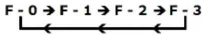
- F-0: exit menu mode
Press the SET-button [2] when the display shows F-0 to exit the setup menu and return to temperature indication.
- F-1: password mode
When password mode is enabled, the user can not change the temperature settings on the station unless he or she knows the password.
Press the set-button [2] once to enter password mode. Press the ▲[4]- or ▼[3]-button to change display between 000 and 100, with 000 indicating password mode disabled and 100 indicating password enabled. Press the set-button [2] to return to the setup menu.
• F-2: temperature correction mode
Press the set-button [2] once to enter temperature correction mode. Press the ▲[4]- or ▼[3]-button to enter a correction factor for the temperature, e.g. when the display shows 300°C but the actual temperature is only 290°C, add 10°C to the shown correction value.
When in °C negative values are indicated with a minus in front; in °F negative values are indicated by a blinking display (5s interval). Press the set-button [2] to return to the setup menu.
• F-3: unit of temperature
Press the set-button [2] once to enter temperature mode. Press the ▲[4]- or ▼[3]-button to change between °C and °F. Press the set-button [2] to return to the setup menu.
VTSSC70
SOLDERING
IMPORTANT NOTE
Do not use temperatures in excess of 410^ C ( 770^ F) for normal soldering and desoldering purposes. The device can be used at higher temperatures for short periods of time. EXERCISE GREAT CAUTION WHEN DOING SO.
CAUTION
Do not touch the metal parts of the soldering iron while the unit is being used or while it is cooling in order to avoid burns.
- Set the power switch [6] to the "ON"-position.
- Press the up-button (▲) [4] until the display [1] indicates 250°C (or 482°F). The unit [B] is shown next to the temperature [A]. When the temperature is stable, the heating indication [C] is off. Note: to change the indicated unit, see § parameter settings above.
- Tin the surface of the soldering tip by applying a new protective layer of solder.
- Set the iron to the desired working temperature.
• Always return the soldering iron to its stand between uses.
9. Common causes for tip failure
• The temperature of the tip exceeds 410°C (770°F)
- The tip is not sufficiently tinned
- Wiping the tip on a surface with a high sulphur content or on a dirty or dry sponge
- Contact with organic or chemical substances such as plastic, resin, silicone and grease
- Impurities in the solder and/or a low tin content
10. Tip maintenance
The soldering uses extremely high temperatures. Make sure that the unit is switched off for maintenance purposes.
Remove the tip and clean it after heavy or moderate use. We recommend cleaning the tip daily if the station is used frequently.
The supplied soldering tip is made of copper covered with a layer of iron. It will retain its projected life span if used properly.
- Always tin the tip before returning it to the holder, prior to turning off the station or to storing it for long periods of time. Wipe the tip on a wet sponge or use our tip cleaner before activating the device.
• Using excessive temperatures (more than 400^ C or 750^ F) will shorten the life span of the tip. - Do not exercise excessive pressure on the tip while soldering, as this may cause damage to the tip.
- Never clean the tip with a file or with abrasive materials.
- Do not use flux containing chloride or acid. Use only resinous fluxes.
- If an oxide film has formed, you should remove it by buffing carefully with a 600-800 grit emery cloth or by using isopropyl alcohol and consequently applying a new protective layer of solder.
- Set the desired temperature after allowing the unit to idle at 250^ C for three minutes. The station will be ready for use once the set temperature is reached.
IMPORTANT
Remove and clean the tip daily. Remove excess solder from the barrel nut assembly when installing a new tip, otherwise the tip may be fused to the heating element or to the retaining assembly.
11. Maintenance
- Soldering tips can be replaced simply by unscrewing the barrel nut assembly. Turn off the station and allow it to cool down first. Damage to the soldering station may occur if the system is left on and the removed tip has not been replaced.
- After removing the tip, you should blow out any oxide dust that may have formed in the tip receptacle. Be careful not to get dust in your eyes. Replace the tip and tighten the screw. Pliers can be used to avoid contact with hot surfaces BUT SHOULD BE USED WITH CAUTION because over-tightening may cause damage to the element or fuse the tip to the element.
- The outer cover of the iron and station may be cleaned with a damp cloth using small amounts of liquid detergent. Never submerse the unit in liquid or allow any liquid to enter the case of the station. Never use any solvent to clean the case.
- If the iron or station should become faulty or, for some reason does not operate normally, the system should be returned to the service department of your authorized dealer or service agent.
VTSSC70
12. Technical specifications
| max. heater power for soldering iron | 80W |
| temperature range | 200 - 480°C (392 - 896°F) |
| low-voltage iron | 32V AC |
| weight | L.58kg |
| dimensions | 185 x 100 x 170mm |
Use this device with original accessories only. Velleman nv cannot be held responsible in the event of damage or injury resulted from (incorrect) use of this device. For more info concerning this product and the latest version of this user manual, please visit our website www.ve lleman.eu. The information in this manual is subject to change without prior notice.
© COPYRIGHT NOTICE
This manual is copyrighted. The copyright to this manual is owned by Velleman nv. All worldwide rights reserved. No part of this manual may be copiec, reproduced, translated or reduced to any electronic medium or otherwise without the prior written consent of the copyright holder.
GEBRUIKERSHANDLEIDING
1. Inleiding
- reservesoldeerbout: VTSSC7/SP1
5. Omschrijving
Velleman® Service and Quality Warranty
Velleman® has over 35 years of experience in the electronics world and distributes its products in more than 85 countries.
All our products fulfil strict quality requirements and legal stipulations in the EU. In order to ensure the quality, our products regularly go through an extra quality check, both by an internal quality department and by specialized external organisations. If, all precautionary measures notwithstanding, problems should occur, please make appeal to our warranty (see guarantee conditions).
General Warranty Conditions Concerning Consumer Products (for EU):
- All consumer products are subject to a 24-month warranty on production flaws and defective material as from the original date of purchase.
- Velleman® can decide to replace an article with an equivalent article, or to refund the retail value totally or partially when the complaint is valid and a free repair or replacement of the article is impossible, or if the expenses are out of proportion.
You will be delivered a replacing article or a refund at the value of 100% of the purchase price in case of a flaw occurred in the first year after the date of purchase and delivery, or a replacing article at 50% of the purchase price or a refund at the value of 50% of the retail value in case of a flaw occurred in the second year after the date of purchase and delivery.
• Not covered by warranty:
- all direct or indirect damage caused after delivery to the article (e.g. by oxidation, shocks, falls, dust, dirt, humidity...), and by the article, as well as its contents (e.g. data loss), compensation for loss of profits;
- frequently replaced consumable goods, parts or accessories such as batteries, lamps, rubber parts, drive belts... (unlimited list);
- flaws resulting from fire, water damage, lightning, accident, natural disaster, etc. ...;
- flaws caused deliberately, negligently or resulting from improper handling, negligent maintenance, abusive use or use contrary to the manufacturer's instructions;
- damage caused by a commercial, professional or collective use of the article (the warranty validity will be reduced to six (6) months when the article is used professionally);
- damage resulting from an inappropriate packing and shipping of the article;
- all damage caused by modification, repair or alteration performed by a third party without written permission by Velleman®.
- Articles to be repaired must be delivered to your Velleman® dealer, solidly packed (preferably in the original packaging), and be completed with the original receipt of purchase and a clear flaw description.
- Hint: In order to save on cost and time, please reread the manual and check if the flaw is caused by obvious causes prior to presenting the article for repair. Note that returning a non-defective article can also involve handling costs.
- Repairs occurring after warranty expiration are subject to shipping costs.
- The above conditions are without prejudice to all commercial warranties.
The above enumeration is subject to modification according to the article (see article's manual).
NL
- To all residents of the European Union
- Important environmental information about this product
- If in doubt, contact your local waste disposal authorities.
- Safety Instructions
- General Guidelines
- VTSSC70
- Features
- Overview
- Description
- Operating Temperature
- Operating instructions
- GENERAL
- PARAMETER SETTINGS
- SOLDERING
- IMPORTANT NOTE
- CAUTION
- Common causes for tip failure
- Tip maintenance
- IMPORTANT
- Maintenance
- Technical specifications
- © COPYRIGHT NOTICE
- GEBRUIKERSHANDLEIDING
- Inleiding
- Omschrijving
- Velleman® Service and Quality Warranty
- General Warranty Conditions Concerning Consumer Products (for EU):
- The above enumeration is subject to modification according to the article (see article's manual).
- NL
Brand : VELLEMAN
Model : VTSSC72
Category : Welding machine