
D2 - Switch ABB - Free user manual and instructions
Find the device manual for free D2 ABB in PDF.
| Product type | Programmable digital timer switch |
| Model | D2, D2 Plus, D2 Synchro |
| Brand | ABB |
| Supply voltage | 230 V AC +/-10% (standard models) ; 110 V AC +/-10% (D1 Plus 110) ; 24 V AC/DC +/-10% (D1 Plus 24) |
| Frequency | 50-60 Hz |
| Output type | Changeover relay, NO contact (16(10)A / 250 V~) and NC contact (16(2)A / 250 V~) |
| Number of outputs | 1 or 2 depending on model |
| Programming capacity | 64 programs |
| Special programs | Random, Cyclic, Holidays |
| External input | Yes (except Synchro models) |
| Manual override | Yes (permanent or temporary) |
| External memory (EMD) | Yes (Plus and Synchro models, via D KEY) |
| GPS/DCF77 receiver | Optional (Synchro models) |
| Degree of protection | IP20 |
| Operating temperature | -5 °C to +55 °C |
| Backup battery life | 6 years (lithium battery) |
| Clock accuracy | +0.5 s/day at 25 °C |
| Cable cross-section | 1...6 mm² |
| Dimensions (approx.) | 90 x 70 x 60 mm |
| Weight (approx.) | 200 g |
| Available languages | French, English, German, Italian, Spanish, etc. |
Frequently Asked Questions - D2 ABB
User questions about D2 ABB
0 question about this device. Answer the ones you know or ask your own.
Ask a new question about this device
Download the instructions for your Switch in PDF format for free! Find your manual D2 - ABB and take your electronic device back in hand. On this page are published all the documents necessary for the use of your device. D2 by ABB.
USER MANUAL D2 ABB
D12C5M258763R0621
D1PLUS2CSM257583R0621
D1PLUS242CSM256403R062
D1PLUS1102CSM258673R0621
D1 SYNCHRO2CSM257493R0621
D2 2CSM256313R0621
D2PLUS2CSM277583H0521
D2 SYNCHRO 2CSM277353R0521

1099G20LWSO2
D1

D2
Digital time switch
Interruttore orario digitale
Int. horario digitale
Horloge digitale
Digitale Wochenschaltuhr
ψηφ.χρονδιακόπης
Digital time switch
PeneBpeMeHHUHbp
Int. horario dig
Digitale Schakelklok
Zegar cyfrowy

1 Description of equipment 1
1-1 Operational features 2
1-2 Technical features 3
1-3 Display (Fig. 1) 4
1-4 Function keys 5
1-5 Combined key functions 5
1-6 Connections 6
1-7 First switch ON 6
2 Menus and programming 7
2-1 Menus - overview 7
2-2 Forcing priority and programs 8
2-3 Create a new program 9
2-4 Check a program 11
2-5 Modify a program 11
2-6 Delete a program (fast method) 12
2-7 Copy a program 12
3Clock programs and settings 12
3-1 Standard Program 13
3-2 Random Program 13
3-3 Cyclic Program 14
3-4 Holidays Program 14
3-6 Delete 15
3-7 Manual 16
3-8 Options 17
3-8-1 Languages 17
3-8-2 Date/Time 17
3-8-3 External input 19
3-8-4 Maintenance 20
3-8-5 Hour meter 21
3-8-6 Back-lighting 21
3-8-7 Warranty 21
4 External Memory Device (EMD) 22
1 Description of equipment
The digital time switch is a weekly programming clock which enables the automatic switching on of different loads on the basis of a timed programming that is sufficiently flexible to allow or exclude the activation depending on the day of the week (for schools, offices, public places, etc.).
With the PLUS and SYNCHRO versions it is also possible to save-copy or read one or more programs on different devices using the D KEY programming key.
Safety
Carefully read this manual before assembling the product and putting it into operation.
This equipment must be assembled and connected solely by adequately skilled personnel.
The equipment contains a non-removable battery and it must not be disposed of as urban waste but recycled in order to protect the environment. Failure to

comply with the requirements of EU Directive 2006/66, and the national legislations for implementation of this Directive, for the disposal of products at the end of their service life, is punishable by law.
1-1 Operational features
| Model (series) | D1 D1 | Plus | D1 Synchro | D2 D2 | Plus | D2 Synchro |
| Channels (circuits) 1 2 | ||||||
| Programs which may be memorised | 64 | |||||
| Special programs (Random, Cyclic, Holiday) | ✓ | |||||
| Weekly/annual time | ✓ | |||||
| External input | ✓ | ✓ | ✓ | ✓ | ||
| Manual forcing | ✓ | |||||
| External Memory Device EMD | ✓ | ✓ | ✓ | ✓ | ||
| GPS or DCF77 receiver (optional) | ✓ | ✓ | ||||
1-2 Technical features
| Power supply voltage 230 V AC +/- 10% 110 V AC +/- 10% (D1 Plus 110) 24 V AC / DC +/- 10% (D1 Plus 24) | |
| Frequency 50-60 Hz | |
| Protection rating IP20 | |
| Outlet type Potential-free relay exchang e contact; N.O. contact = 16(10)A / 250V~ (limited current with Resistance for Zero Crossing of high value); N.C. contact = 16(2)A / 250V~ N.O./N.C. contacts = 16(2)A / 250V~ (D1 Plus 24, D1 Plus 110) | |
| Maximum AC output N.O. 16(10)A / N. | C. 16(2)A N.O./N.C. 16(2) (D1 Plus 24, D1 Plus 110) |
| Operating temperature from -5°C to +55°C | |
| Storage temperature from -10°C to +65°C | |
| Absorption/Self-consumption 6.5 VA single channel / 7.8 VA twin channel | |
| Cross-section of cables at terminals 1 | ..6 mm² |
| CE standards LVD/EMC EN60730-2-7 | |
| Languages available on equipment Italian, English, German, French, Spanish, Swedish, Portuguese, Dutch, Russian, Polish, Greek | |
| Backup in case of power failure 6 years from first switch on, guaranteed by lithium battery | |
| Nominal pulse voltage | 4kV |
| Operational precision + 0.5 sec/day at | 25°C |
| Maximum pilotable power | ||||
| 3000W 3000W 1100W | 900W(125 μF) | 7W - 23W (max.23 lamps) | ||
| Models D1 PLUS 24 - D1 PLUS 110 | ||||
| 2300W 2300W 1000W | 500W(70 μF) | 7W - 23W (max.18 lamps) | ||
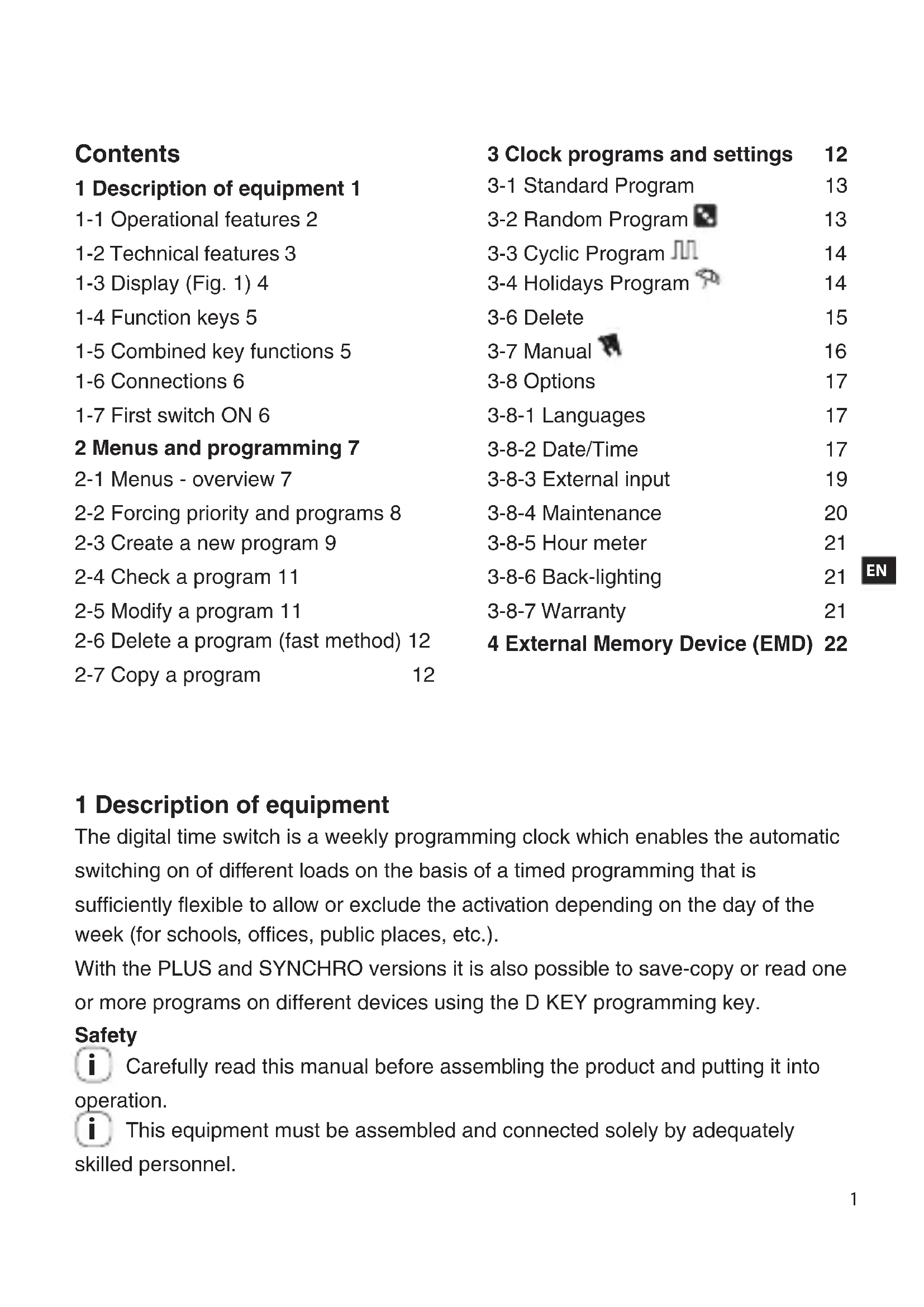
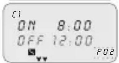
1-3 Display (Fig. 1)

| C1/C2 | Channel 1/Channel 2 OFF/ Channel deactivated | ||
| A | Manual forcing of channel ON / Channel active | ||
| B | Random programs Cyclic programs | ||
| C | Holidays icon Keyboard lock | ||
| D | GPS or DCF77 signal reception indication | ▲ Scroll up | |
| P88 | Program no. selected P01-P64 | ▼ Scroll down | |
The striped bar on the display also shows:
Progress, ref. Fig.2 (e.g. deletion ref. subsection 3-6).
Display hours, ref. Fig.3.
The display shows alternately (for a few seconds) the date and the time and the programs or forcings set.
1-4 Function keys
| 入門 | Enter main menu (from initial screen). Exit from any setting |
| ▲ | Scroll list upwards. Increase a numerical value or change a parameter. Hold down to display status of channel 1 until button is released (under normal operation). |
| ▼ | Scroll list downwards. Decrease a numerical value or change a parameter. Hold down to display status of channel 2 (twin channel models) until button is released (under normal operation). |
| OK | Confirm proposed setting. |
| RESET | Reset equipment (NOTE: The programs and external input settings are not deleted). |
1-5 Combined key functions
| Function Combined keys | ||
| Lock / unlock keys (+) | 2 secs. | |
| Temporary manual forcing of channel 1 and 2 (ref. subsection 3-7). Alternate pressure to change it from TEMP ON to TEMP OFF. | + Ln1- Rn2+ | |
| Function Combined keys | ||
| Permanent manual forcing of channel 1 and 2 (ref. subsection 3-7). Press for 2 secs. to access PERM and alternate pressure to change it from PERM ON to PERM OFF. | 2 secs. | 2 secs. |
| Return to AUTO mode (if any manual forcing has been activated). | 2 secs. | 2 secs. |

It is necessary to be on the initial screen to carry out any of the above-mentioned functions
1-6 Connections
Maximum distance for external input: 100m
Connection of single channel and twin channel models
Ref. Fig. 5-1 to Fig.5-3.
Connection of Synchro models
Single channel or twin channel Synchro models with GPS or DCF77 Antenna. Ref. Fig. 6-1 to Fig.6-2.
1-7 First switch ON
The equipment is supplied without any settings.
- Press RESET with a pointed object to unlock the equipment (ref. Fig.4). Set following data:2.
LANGUAGES (ref. subsection 3-8-1).
DATE/TIME (Year, Month, Day, Time, Time Zone (ref. subsection 3-8-2)).
If there is a power failure, the Date/Time is memorised, and the digital switch: disables relay(s), deactivates back-lighting, if active,
displays flashing date and time for 2 minutes, and then changes to stand-by mode (display switched OFF) storing all the programmed data, until the mains power supply is reconnected or until a button which restarts the counter for the stand-by mode is pressed for more than 1 sec.
2 Menus and programming
2-1 Menus - overview
The menus listed from 1 to 8 are in the sequence present in the equipment.

* Excluding Synchro models.
Press1. MENU.
The first menu which may be selected appears (P Standard)》 Scroll the various menus using keys A. Confirm desired menu with 3. OK.
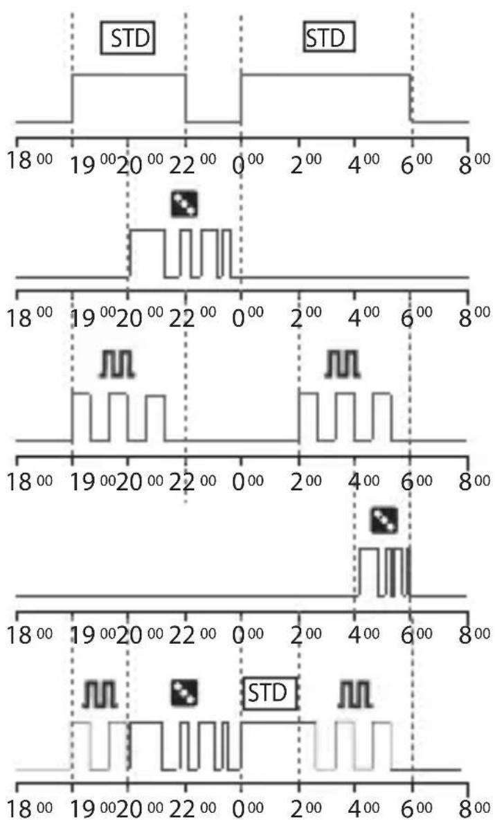
2-2 Forcing priority and programs
A priority is assigned to every type of program, as shown alongside.
i Take the priorities into consideration when various types of programs are programmed for the same period of time.

EN

P01: Standard Program ON 19:00 - OFF 22:00
P02: Standard Program ON 00:00 - OFF 06:00
P03: Random Program ON 20:00 - OFF 00:00
P04: Cyclic Program ON 19:00 - OFF 22:00
P05: Cyclic Program ON 02:00 - OFF 06:00
P06: Random Program ON 04:00 - OFF 06:00
Behaviour of output load with programs from P01 to P06, according to the priorities.
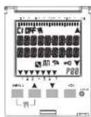
2-3 Create a new program
Procedure valid for all types of programs Further settings are described in the individual programs.
Selection of program type (e.g. with P Standard):


Press1. MENU.
Select program type using keys
Press3. OK to confirm selection.
The number of free programs appears for 3 secs.
The first program in the memory appears.
Press4. for 2 secs.
The display shows the first empty program.
Press5. OK to confirm.
The program number is selected.
Followed by channel setting.
Select channel (only twin channel models)

Set channel (twin channel) using keys
C1/C2 or both flash.
Press2. OK to confirm.
The channel is set.
Followed by day setting.
Set day
Select the day or group of days in which the program must be executed.

Set the day or group of days using keys
The flashing arrow indicates the day or group of days selected.
Press2. OK to confirm.
Followed by TIME/ON setting.
Set TIME/ON
Set program start time using keys in the format hh/mm.

Single pressure of keys moves field by minutes. Prolonged pressure of keys moves field by hours
Press2. OK to confirm.
The seconds field appears.
Set the seconds using keys A.
Press4. OK to confirm.
The program start time has been set> Followed by TIME/OFF setting.>
Set TIME/OFF

Set program end time using keys A.
Repeat operations as per TIME/ON.
Press2. OK to confirm.
The program end time has been set> Press3. OK to confirm program end time.

Set ANNUAL PERIOD
Enables a defined period to be set, in which the program set up previously must be executed.
The period defined in the annual program is repeated cyclically every year.

Set the start and end of the period in the format 1. dd/mm-- using keys
Press2. OK to confirm every field. The annual period is set.

- Press MENU to exit programming.
2-4 Check a program
Access desired program menus (STANDARD P, CYCLIC P...) by pressing MENU.

Select the program type from the menu (e.g. RAN-1. DOM P) using keys
Press2. OK to confirm. The programs of the same type in the memory are displayed.
Select the program to be checked using keys. The display shows the settings cyclically.
2-5 Modify a program
- Press OK to confirm program to be modified.
Set new values as described in subsection 2-3.2.
2-6 Delete a program (fast method)

Select from the menu the program type to be deleted 1. using keys
e.g. RANDOM P» Press keys A simultaneously for 2 secs.

The display shows "ERASE". Press3. OK to confirm. The display shows "EMPTY". The program is deleted.
EN
2-7 Copy a program
Select from the menu the program type to be copied 1. (e.g. RANDOM P) using keys AV
The program number flashes.
Press2. OK for approx. 3 seconds
The program is copied in the first free position in » the memory.
The first modifiable data (channel) is displayed flashing.

Modify data as described in subsection 2-3.3.
i
2 programs with the same data cannot coexist!
3 Clock programs and settings
- Press MENU to access available menus. Scroll menus using keys and press OK to confirm.
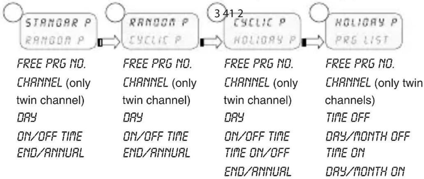
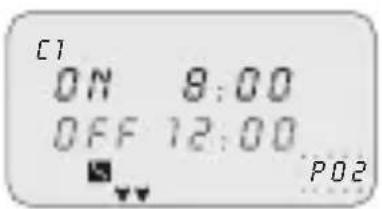
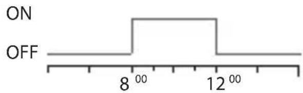
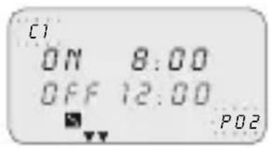
3-1 Standard Program
Enables a defined period of an ON and OFF cycle to be set up.

i For programming ref. section 2-3.
Example of set up from image:
Standard Program ON 8:00 - OFF 12:00.
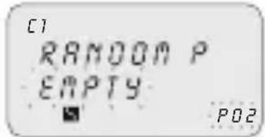
3-2 Random Program
Enables one or more channels to be activated and deactivated in a random manner within an established period.

i For programming ref. section 2-3.

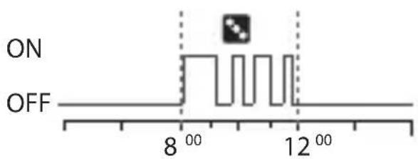
Example of set up from image:
Random Program ON 8:00 - OFF 12:00.
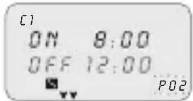
3-3 Cyclic Program
Enables a series of pulses to be executed within a defined period.
The ON time and the OFF time may vary from 1 sec. up to 23:59:59 hours

For programming ref. section 2-3.
In addition, set the time of 1. TIME ON and TIME OFF using keys

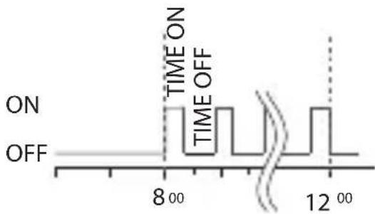
EN Example of set up:
Cyclic Program ON 8:00 - OFF 12:00.
Timing of TIME ON 10 min and TIME OFF 15 min.
3-4 Holidays Program

This enables a period of suspension of the programs to be set, for example, for summer closing.
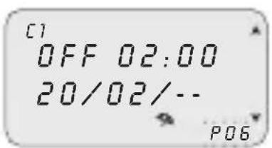
Select HOLIDAY P as described under subsection 1. 2-3.
Set the suspension start time (OFF) using keys 2. Press3. OK to confirm.
Set suspension start date using keys AV in format dd/mm/-.
Set the suspension end time and date (ON) as per 5. operations 2 to 4.
3-5 PRG List
This menu enables any program in the memory to be displayed, modified or deleted.


Scroll to "PRG LIST" using keys
Press2. OK to confirm.
The number of free programs appears.
The first program in the memory is displayed.
Select the desired program using keys A.
i Ref. subsections 2-2 to 2-4 for details on checking, modifying or deleting data.
3-6 Delete
This menu enables different type of deletions to be made.

Scroll to 1. ERASE using keys
Press2. OK to confirm.
The type of deletion in the sub-menu is accessed (ref. table below).
Select deletion type using keys
Press3. OK to confirm deletion.
Press MENU to cancel deletion.
| Sub-menu Function | |
| SING PROG Delete single programs selected | |
| ALL PROG | Delete all programs All programs in the memory will be deleted! |
| HOLIDAY P | Delete all holiday programs |
3-7 Manual
This enables the status of the outputs to be forced manually regardless of active program. Possible settings:
| Forcing mode | Display symbol | Channel-Condition | Forcing function |
| AUTO ON | C2 | No forcing on channel; management from program. | |
| PERM | A | C1 OnC2 On | Permanent channel activated. |
| PERM | B | C1 OFFC2 OFF | Permanent channel de-activated. |
| TEMP | C | C1 OnC2 On | Channel activated until next program activity. |
| TEMP | D | C1 OFFC2 OFF | Channel de-activated until next program activity. |
Activate a forcing

Select sub-menu "OVERRIDE" using keys A.Y
Press2. OK to confirm.
Press combined keys (ref. subsection 1-6) to select 3. channel (only twin channel models).
The display shows information on channel(s) (ref. table above).
Set type of forcing using keys.
Press5. OK to confirm selection.
It returns to the main screen.
The display shows the type of forcing on the channel.
De-activate a forcing
Press combined keys of the channel to be de-activated (ref. subsection 1-6) for 1. approx. 2 secs.
Select "AUTO" mode to deactivate using the menu (ref. subsection "Activate a forcing").
3-8 Options
This enables various clock parameters to be set.

Select "OPTIONS" using keys. Press2. OK to confirm. The sub-menus follow.
3-8-1 Languages
This enables the desired interface language to be set.

Select the "LANGUAGE" sub-menu using keys. Press2. OK to confirm. Select the desired language using keys. Press4. OK to confirm.

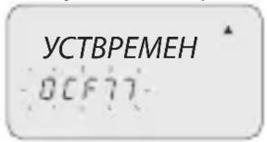
3-8-2 Date/Time
This enables the date and time of the equipment to be set.
If the equipment is reset the date must be set again.

Select "TIME SET"1. using keys.. Press2. OK to confirm. Set YEAR, MONTH, DAY, HOUR, MINUTES, 3. respectively, using keys.
Single pressure of keys moves field by minutes. Prolonged pressure of keys moves field by hours Press4. OK to confirm.
Date and time are set.»
Followed by "SUM/WIN" setting.»
Summer/winter time change
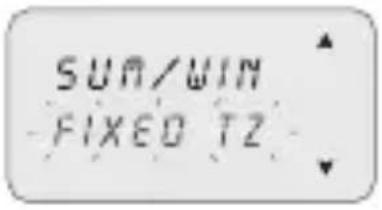
Select switching type using keys.
Press2. OK to confirm.
Set values (ref. table) using keys.
Press4. OK to confirm.
| Possible selections on display | Summer switching Winter | switching |
| NONE | None None | |
| EUROPE | Last Sunday in March Last | Sunday in October |
| USR | Second Sunday in March First | First Sunday in November |
| FREE TZ | Week/day (Sun.) freely programmed | Week/day (Sun.) freely programmed |
| FIXED TZ | Fixed date freely pro-programmed (e.g. 28/02) | Fixed date freely pro-programmed (e.g. 29/10) |
Time Zone GPS (only GPS and DCF77 models)
Set the local time by adding/subtracting the number of hours with respect to GMT, the so-called T ZONE (e.g. Italy, T ZONE +1).

i After setting TIME SET (ref. subsection 3-8-2). Select "GPS" using keys. Press2. OK to confirm.

Select the SUM/WIN mode (ref. previous table).3. Set number of T ZONE hours using keys. Press5. OK to confirm.
The time change has been set. It returns to the main screen.
Time Zone DCF77 (only GPS and DCF77 models)
The receiver, on the contrary to the GPS, transmits the time with the summer/ winter correction.
It is necessary to set the correct number of hours with respect to the Frankfurt position.

Select "DCF77" using keys
Press2. OK to confirm.
Set the T ZONE number as described in the previous 3. operations from 4 to 5.
3-8-3 External input
This enables manual ON and OFF forcing functions to be executed from a remote position, (ref. section 3), by means of buttons or switches.
Function not available for the SYNCHRO models (the "EXT INPUT" item is not available in the "OPTIONS" menu).

Select the "EXT INPUT" sub-menu using keys
Press2. OK to confirm.
Select switching type (ref. table below) using keys 3.

Press4. OK to confirm.
In order to deactivate settings made, repeat actions from 1 to 2.
Press OK to confirm "DEACTIVAT" selection.
| Display selection | Channel C1 or C2 (twin channel) | Symbol Function External | control | |
| PERM ON | OFF | Permanent forcing of channel on ON or OFF. | — | |
| TEMP | - | Temporary forcing of the channel until the next switching of a program set previously. | — | |
| TIMER ON | OFF | Forcing of a timed channel (e.g. stairway lighting control). Time may be set in format hh:mm:ss. | # | |
3-8-4 Maintenance
This enables a period of operation in ON to be set for each channel. After this period, the clock signals the need for an intervention with the message "C1 MAINT" or "C2 MAINT", alternating with the current data.

Select the "MAINTENAN" sub-menu using keys A C1 flashes.
Select channel using keys (twin channel models).
Press3. OK to confirm.
Set number of hours using keys A.
Press5. OK to confirm.
In order to modify or rest the values, follow instructions from 1 to 5.
Cancel maintenance notice
i Pressing the OK button on the main screen for 2 secs. eliminates the "MAINT" message shown on the display.
3-8-5 Hour meter
This enables the number of hours of the channels in the ON status to be displayed.

Select the "HOURMETER" sub-menu using keys
Press2. OK to confirm.
Select channel using keys A.
The display shows the hours of operation.

i Press keys+ to zero.
3-8-6 Back-lighting
This enables the display backlighting time to be set.

Select the "BACKLIGHT" sub-menu using keys
Press2. OK to confirm.
Select using keys between: FIXED ON,
FIXED OFF or TEMP 6SEC.
Press4. OK to confirm.

3-8-7 Warranty
This enables the time since the putting into service of the clock to be displayed in days.

Select the "WARRANTY" sub-menu using keys
Press2. OK to confirm.
The display shows the time, as described above. Counter may not be zeroed.

4 External Memory Device (EMD)
The EMD is an external memory card, which is able to manage 64 programs, including the holidays.
The EMD is the D KEY programming key.

Insert the EMD.1.
The display shows the memory management » menu
Select the desired sub-menu (ref. table) using keys 2.

Press3. OK to confirm every selection.
| Sub-menu Function Notes | ||
| EXECUTE | Execute programs directly from EMD | The programs are executed only from EMD |
| SAVE->END | Save all clock memory on EMD | Overwrite all programs already present on EMD |
| LOAD<-END | Load all content from EMD on clock memory | Overwrite all programs present on clock |
| READ | Read programs from EMD Display | ay only the programs present on EMD |
| HOLIO->END | Load Holiday programs from clock to EMD | Overwrite all Holiday programs present on EMD |
| HOLIO<-END | Load Holiday programs from EMD to clock | Overwrite all Holiday programs present on clock |
| ERASE | Delete programs present on EMD | Permanently delete all EMD memory |

- Press MENU to exit.
Press2. OK to confirm "ABORT" selection.
The EMD is excluded from the clock.
The EMD memory is no longer recognised.» Withdraw the EMD.3.
Sommario
inhabilita el/los rele/s,
Programa Standar ON hora 8:00, OFF hora 12:00.
3-2 Programa Casual
Programa Casual ON hora 8:00, OFF hora 12:00.
désactive le(s) relais,
3-3 Programme cyclique
2-5 TpoTOnToiOnn TpoypaMaToC
Pntote 1. OK yia va eTlBcaiwote To npoypaumau Tou poketai va tpoTOniOth. PuOmuTe TIG VEC SOTWCS PEPYpafetai OTNV UTOEVOTnTa 2-3.2.
2-6 iaypaqn ppoypaμatoc (ypnyopn μεθoδoc)


Papadjiya puthetaiogε Eikova:
Tuxaio Tpóypaμα ON 8:00 - OFF 12:00.
3-3 Kukliko Tpóypαμα
P02: Standard program
ON 00:00 - OFF 06:00
P03: Slumpprogram
ON 20:00 - OFF 00:00
P04: Cykelprogram
ON 19:00 - OFF 22:00
P05: Cykelprogram
ON 02:00 - OFF 06:00
P06: Slumpprogram
ON 04:00 - OFF 06:00
3-1 Standard program
Medger installing av en bestamd period for en ON / OFF cykel.

Satt i EMD-minnet.1.
Displayen visar menyn for minenshantering.
Välj önskad untermeny (se tabellen) med knapparna 2.

OTKJIIOUaETpeIe (OdHO nnn 6oJee),
DeakTNBnpyeT noDCBeTky, ecn6bIa BkIIOyeHa,
BbICBeuBaET MraOuIe YnCNo N BpeM B TeueHne 2 MNHyT, a 3aTeM nepexoJNT B XdyuI pexIM (stand-by) (DncnIe OTKIoueH), NOdEprXNBaB B namrN BCE 3anpoRpaMMIOBaHHbIe DaHHbIe Do MOMeHTa BOCCTaHOBJIeHNA CTeBOrO HAnpJxHEny IIN PPOdoJIxntbHOrO HaXaTnaB TteU. 1 cekyHdbI KJIaBnSh, KOtOpA rpe3aNyckaet OTcHET BpeMeHn DnJ XdyUeero peXIma.
2 MeHIO n nporpaMMnpoBaHne
2-1 MeHIO - 0630p
Mehno, nepeuicneHHbIe ot 1 do 8 noBnTcB TaKoN nocJeIOBaTeJIbHOCTN, B KaKoN haojTcB aannapate.
1
PCTAH
P Cny
2
P Cny4
NPUKNKNIU
3
PUCNNU
PДBbIX
4
PABbIX
CNCOKP
No CBOBQIOHOI IPOP.
KAHAJI (TOJbKO
2-kaHaJIbHbIe)
ENb
BPEM BKL/OTK
KOHEU/TOIDHbI
No CBOBODHOI PPOPT.
KAHAJI (TOJIbKO
2-kaHaJIbHbIe)
AEBb
BPEM BKN/OTK
KOHELYIPOINHbI
No CBOBODHOI PPOP.
KAHAJI(TOJIbKO
2-kaHaJIbHbIe)
BPEM BKL/OTK
BPEM BKL/OTK
KOHEU/TOIDHbI
No CBOBODHOI PPOPT.
KAHAJI (TOJIbKO
2-kaHaJIbHbIe)
BPEMOTK
DEHb/MEcRUOTK
YAC BKJ
DEHb/MEcRU BKJ
5
CINCOK PP
OHTKA
6
OuNCTKA
BO3BPAT
7
BO3BPAT
ONUIN
8
BO3BPAT
ONUIN
ПОВЕРNTb
N3MEHHTb
OTMEHHTb
OДHAПPOR
BCE IPO
BbIXOJIHbIE
KAHAJI(TOJIbKO
2-kaHaJIbHbIe)
ABTO
NOCTOTK
NOCT BKJ
BPEMEH BKJ
BPEMEHOTK
3bIK
DATA/BPEM
BXOД-HAPYЖнБI*
TEXOBCJYKUBAHNE
CUYHKYACOB
3AДнЯ ПОДCBETKA
TAPAHITNIA
- 3a nckJIoueHnem moJeIeSynchro.
Haxatb KnaBnuy 1. MEHIO.
IopBnEeTc npBoe MeHIO dIy Bb6opa (PCTAHD)»
PpocmoTpeb pa3HbIe MeHIO KnaBnwaMn 2.
PoiTBepnItb XeJaemoe MeHIO KnaBnwei 3. OK.
2-2ПриорпетпринундпельнывключениnporpaMM
Kakdomy Tnny nporpaMMbl npCBAuBaETcnpOpNTet, kak yka3aHo Ha COceDHei CXeme.
B cnyuae nporpaMMnpOBaHna pa3HbIX BnOIB nporpaMM Ha TOT Xe CaMbI NepNOB BpeMeHN CNeDyET yYeCTb IN PpNOpNTeTHOCTb.

HANBbIcIeI npOpntET
P01: nporpamma CtahandaptnaBKN 19:00-OTK 22:00
P02: nporpamma CtaHapTnaBKJI 00:00-OTK 06:00
P03: nporpamma CnyaHna BKI 20:00-OTK 00:00
P04: nporpamma Lnkneuecka BKI 19:00-OTK 22:00
P05: nporpamma Luknueckaj BKJ 02:00 - OTK 06:00
P06: nporpamma CnyaHna BkI 04:00 - OTK 06:00
YcTaHOBnTb IOnHbI INEPNO
I03B0JrET yCTaHOBtB ONpeJeHbI IepNoI, BO BpeM KOTOpO raHee 3aDaHHa npOrpAMMa DOJxHa BblONHrTbcra.
OnpeJeHbB B roDnHOB nporpamme nepnoN NOBTOPReTcN KInueckn exe- roHO.

BBeCTn Haayano n KOHeu nepnoa B opMaTe 1. dM/-- KnaBnShaMn A
PoiTBePdntbKaXdoe nOJe KnaBnWei 2. OK.
L R M G U R G E YCTBPEMEH
BbI6paTb IOmEnIO «LANGUAGE» KnaBnAmn AY
IoTBePntb KnaBnwei 2. OK.
BbipbXeJaembln3bIKKnaBnwaMn
B cIyuae BbInonHeHnC6pOca, CneJyET 3aHOBO BBecTn DaTy.
LANGUAGE YCTBPEMEH
Bb6paTb «YCTBPEMH»1. KnaBnshaM
PoiTBePdntb KnaBnwei 2. OK.
BBeTn IOD, MECaU, DEHb, YAC, MNHYT 3.
COOTBETCTBYUIMN KJIaBNiAmN
Ozhopa30Boe haxatne knaBnI nepemeaet noJe MNHyT. PpOJXITbHoe haxatne knaBnI nepemeaET NOJIe YacOB.
IoTBePntb KnaBnwei 4. OK.
Yncno IN Bpem 3aHaHbI.
CneyuTe yctaHOBka «JIETO/3IMA».»
CmeHaJIeTHero/3mMheroBpeMeHn
JIETO/3NMA
ΦUKC3OHA
BbipbTnpeKIOueHnaBnAmn
IopTBePdntb KnaBnwei 2. OK.
BBeTn 3NaueHnra (cm. Ta6nua) KnaBnssamn
IoTBePdntb KnaBnwei 4. OK.
BBeCTN KOJIueCTBO YacOB 30HbI T ZONE KJIaBnJAmn 4.
A
IopTBePdntb KnaBnwei5. OK.
CmeHa BpeMeHn 3aDana.
Bo3BpaaetaHa npedbIyuyo 3KpaHHyo cTpaHnuy.
Time Zone DCF77 (ToIbko moJeNn GPS n DCF77)
B otTnue ot GPS, npneMHnk nepeaet Bpemc KoppeKneJ neTheo/3mHero BpemeHn.
CneyuET BBecTN npabnIbHoe KOINueCTBO yacOB no OTHOWeHIO K nO3nU IN PhaHKpypTa.
Bbipb《DCF77》KnaBnwaMn
IodTBepdntb KnaBnwei 2. OK.
BBeCTn Homep T ZONE, kak onncaHO B npedbyux 3.
onepaunx ot 4 do 5.
3-8-3 BheunBxOa
I03BOJRAET BbINOJIHnTb 4yHKUIN pyuHbIX npHydnteJIbHbIX BKIOUeHNI BKJI IN OTK c ydaJIeHHoro yCTpOInCTBa, (cM. pa3d. 3), npN NOMOUI KHOJOK IIN BBIKIOUaTeJeN.
BBeCTN KOJIueCTBO YacOB KJnABnShaMn A
IoTBePntb KnaBnwei 5. OK.
i UTo6bI N3MeHnTb IJIb BHOBb 3aDaTb 3HaueHnA, Bbl- NOJHnTb INHCTpyKcNt O1 Do 5.
RU
OTMeHnTb npeDynpexKeHne o Texo6cnyxuBaHnn
Haxatne KnaBnO NK B Teu. 2 cek. Ha rnaBHOJ kpaHHoC TpaHnue ydaJeT coo6eHne «TEXO5C», oTo6paxeHoe Ha dinCnnee.
3-8-5 CyeTnK YacOB
I03BOJRAET KOJIyEcTBo YacOB HaxOxJdeHna KaHaNoB B COCToHn BKJI.
BPEMRA
C4ET4ACOB
BbI6paTb noDmeHIO «CHTUACOB» KnaBnShaMn A
Ha dncnnee BbICBeuHBaETcKoJIueCTBO yacOB pa60Tbl.
000153
Haxatb KnaBnA+V, YTO6bl O6HyIITb.
3-8-6 Повсветka
I03B0JareT 3aadatb BpeM NOcCBETKn Dncnnpe.
CYETYACOB
ПОДCBETKA
BbI6paTb IOmEnHIO «ПОДCBETKA» KnaBnShaMn
IoTBePdntb KnaBnwei 2. OK.
BbI6paTb KnaBnShaMn 3 OndHy n3 onuH: HEPPEPBKJI,
HEPPEPOTKnnBPEM6CEK.
Pecorrer os various menus com as teclas A.
Programa Casual ON hora 08:00, OFF hora 12:00.
Seleccionar "GPS",utilizing as teclas A
Confirmar com 2. OK.
P03: Random programma
ON 20:00 - OFF 00:00
P04: Cyclisch programma
ON 19:00 - OFF 22:00
P05: Cyclisch programma
ON 02:00 - OFF 06:00
P06: Random programma
ON 04:00 - OFF 06:00


- Description of equipment 1
- Menus and programming 7
- 3Clock programs and settings 12
- External Memory Device (EMD) 22
- Description of equipment
- Safety
- 1-1 Operational features
- 1-2 Technical features
- 1-3 Display (Fig. 1)
- 1-4 Function keys
- 1-5 Combined key functions
- 1-6 Connections
- 1-7 First switch ON
- Menus and programming
- 2-1 Menus - overview
- 2-2 Forcing priority and programs
- 2-3 Create a new program
- Selection of program type (e.g. with P Standard):
- Select channel (only twin channel models)
- Set day
- Set TIME/ON
- Set TIME/OFF
- Set ANNUAL PERIOD
- 2-4 Check a program
- 2-5 Modify a program
- 2-6 Delete a program (fast method)
- EN
- 2-7 Copy a program
- i
- Clock programs and settings
- 3-1 Standard Program
- 3-2 Random Program
- 3-3 Cyclic Program
- 3-4 Holidays Program
- 3-5 PRG List
- 3-6 Delete
- 3-7 Manual
- Activate a forcing
- De-activate a forcing
- 3-8 Options
- 3-8-1 Languages
- 3-8-2 Date/Time
- Summer/winter time change
- Time Zone GPS (only GPS and DCF77 models)
- Time Zone DCF77 (only GPS and DCF77 models)
- 3-8-3 External input
- 3-8-4 Maintenance
- Cancel maintenance notice
- 3-8-5 Hour meter
- 3-8-6 Back-lighting
- 3-8-7 Warranty
- External Memory Device (EMD)
- Sommario
- 3-2 Programa Casual
- 3-3 Programme cyclique
- 2-5 TpoTOnToiOnn TpoypaMaToC
- 2-6 iaypaqn ppoypaμatoc (ypnyopn μεθoδoc)
- 3-3 Kukliko Tpóypαμα
- MeHIO n nporpaMMnpoBaHne
- 2-1 MeHIO - 0630p
- 2-2ПриорпетпринундпельнывключениnporpaMM
- YcTaHOBnTb IOnHbI INEPNO
- CmeHaJIeTHero/3mMheroBpeMeHn
- Time Zone DCF77 (ToIbko moJeNn GPS n DCF77)
- 3-8-3 BheunBxOa
- RU
- OTMeHnTb npeDynpexKeHne o Texo6cnyxuBaHnn
- 3-8-5 CyeTnK YacOB
- 3-8-6 Повсветka
Brand : ABB
Model : D2
Category : Switch