
MML24R - Light panel VELLEMAN - Free user manual and instructions
Find the device manual for free MML24R VELLEMAN in PDF.
| Product type | LED matrix light panel |
| Brand | Velleman |
| Model | MML24R |
| Dimensions | 1100 x 100 x 45 mm |
| Weight | 2.2 kg |
| Power supply | 100-240 VAC ~ 12 VDC / 2.5 A (adapter included) |
| Maximum power consumption | 30 W |
| Display | 7 x 120 dots (5 mm pitch) |
| Display area | 910 x 55 mm |
| Pixel pitch | 7.62 mm |
| Available colors | Red, green, yellow, combinations (depending on configuration) |
| Font sizes | Normal (5x7), Bold (6x7), Narrow (4x7) |
| Memory | 26 text pages (up to 210 characters per page) + 16 graphic pages |
| Remote control range | Approximately 40 m (depending on conditions) |
| Viewing angle | Not specified (estimated: 120° horizontal) |
| Connectivity | RS232 port (and USB via included converter) |
| Operating temperature | -5°C to +50°C |
| Operating humidity | 20% to 90% |
| Included software | New Sign for Windows (Win98/ME/NT/2000/XP) |
| Main functions | Message display, appearance/disappearance effects, scheduling, BMP graphics, management of multiple panels (up to 255 IDs) |
| Maintenance and cleaning | Disconnect before cleaning. Use a soft, dry cloth. Do not use harsh chemicals. |
| Safety | Do not open, do not expose to moisture. Use only the provided adapter. |
| Spare parts and repairability | Internal battery for clock backup (replaceable). Remote control and USB converter included. Contact Velleman support for repairs. |
| General information | 2-year warranty (conditions on website). CE marking. Recycling according to local legislation. |
Frequently Asked Questions - MML24R VELLEMAN
User questions about MML24R VELLEMAN
0 question about this device. Answer the ones you know or ask your own.
Ask a new question about this device
Download the instructions for your Light panel in PDF format for free! Find your manual MML24R - VELLEMAN and take your electronic device back in hand. On this page are published all the documents necessary for the use of your device. MML24R by VELLEMAN.
USER MANUAL MML24R VELLEMAN
To all residents of the European Union
Important environmental information about this product
This symbol on the device or the package indicates that disposal of the device after its lifecycle could harm the environment.
Do not dispose of the unit (or batteries) as unsorted municipal waste; it should be taken to a specialised by for recycling.
This device should be returned to your distributor or to a local recycling service.
Respect the local environmental rules.
If in doubt, contact your local waste disposal authorities.
Thank you for choosing VELLEMAN! Please read the manual thoroughly before bringing this device into service. If the device was damaged in transit, don't install or use it and contact your dealer. Features include:
- Colours and font sizes
Visual text effects and graphics - Dependable and durable
Large memory and message storage
Schedule display function
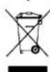
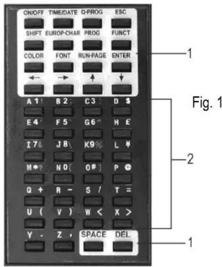
2. Remote Control
- Command keys
-
Character keys
-
Upper case keys (A-Z)
- Lower case keys (a-z)
Numeric keys (0-9) - Symbols (!;...)
European (A)
3. Getting started by Remote Control
Press [ON/OFF]
Press [TIME/DATE] to display the time and date message only. Press [ESC] to cancel time/date display function.
Programming a simple message.
| Step Key to press Description | Display | ||
| 1. [Q-PROG] Stop the sign | and wait for message input | ||
| 2. | [H][E][L][L][O] [SPACE] | Key in [HELLO] using the character keys Tip: If you key in a wrong character, press [DEL] to delete the last character | [HELLO] |
| 3. [ENTER] Run the message [HELLO HELLO] | |||
4. Programming Alternate Characters
Displaying lower-case letters, numbers and symbols using the [SHIFT] key
Please take notice of the indication block which appears on the left hand corner of the sign whenever the [SHIFT] key is pressed.
- Press [Q-PROG] to stop the sign.
- Press [A] to display the character A.
- Press [SHIFT] once. Press any of the keys on the IR remote. The lower-case character keys are active.
- Press [SHIFT] again. Press any of the keys on the IR remote. The numerical keys are active.
- Press [SHIFT] again. Press any of the keys on the IR remote. The green characters are active.
- Press [SHIFT] again to return to the upper-case mode.
NOTE: The upper-case mode is the default mode when beginning to program. Once you press [SHIFT] you are no longer in the upper-case mode. Follow steps 3 to 6 to toggle between the different modes. - Press [ENTER] to run your message.
Displaying European characters using the [EUROP-CHAR] key
- Press [Q-PROG] to stop the sign.
- Press [A] to display the character A.
- Now press [EUROP-CHAR]. Notice that the character has changed into a European style character.
TIP: To return to the normal character, keep pressing [EUROP-CHAR]. Also, press any character to continue to type regular characters. Repeat step 2 and 3 when you want to display a European character. - Press [ENTER] to run your message.
Displaying European characters in lower-case using [SHIFT] and [EUROP-CHAR]
- Press [Q-PROG] to stop the sign.
- Press [SHIFT] once to go into lower-case mode.
- Press [C] to display the character C in lower-case.
- Now press [EUROP-CHAR]. Notice that the character has changed into a European style character.
- Press [ENTER] to run the message.
NOTE: There are 64 European characters to choose from. Refer to the Quick Reference Guide for the European characters table and corresponding characters.
TIP: Use the character G with [EUROP-CHAR] to display Greek characters.
5. Attention-getting Features
Displaying a pre-loaded message or graphics page
Example: Pre-loaded message in page A.
| Step Key to press Description Display | |
| 1. [RUN-PAGE] Stop the sign and wait page data [STOP MODE] | |
| 2. [A] Display page A [PG:A] | |
| 3. [ENTER] Run your message |
NOTE: There are 26 pages (A to Z) to save your messages in.
Link display pre-loaded message
| Step Key to press Description Display | |||
| 1. [RUN-PAGE] Stop the sign and wait page data [STOP MODE] | |||
| 2. | [A] [B] [E] | Display page A, B, E | [PG:A, B, E] |
| 3. [ENTER] Run your message | |||
Using [COLOR] or [FONT] to select a text colour or a different character font
- Press [Q-PROG] to stop the sign.
- Press [S] [U] to display the character.
- Press [COLOR]. The characters have changed colour.
- Press [COLOR] again to view the different colours and select the one you wish to use. The selected colour stays active until another colour is chosen.
- Press [FONT]. Notice the characters have changed to a different font.
- Press [FONT] again to view the different font sizes and select the one you wish to use. The selected font stays active until another font is chosen.
- Press [ENTER] to run your message.
NOTE: Please refer to the Quick Reference Guide for the colour and font size table.
6. Advanced Features
Adding special effects to your message using [PROG]
- Press [PROG] to program a message.
- Press [↓] to select the page edit function.
- Press [] to select page A. You can select from 26 pages (A to Z).
- Press [↑] [↓] to program the page. The sign will read [PAG: A].
- Press [ENTER] to edit the page.
- Enter a word. Press [ENTER].
- Press [↑] [↓] to scroll through the various leading effects and press [ENTER] to confirm.
- Press [↑] [↓] to scroll through the closing effects and press [ENTER] to confirm.
- Press [↑] [↓] to select the display time and press [ENTER] to confirm.
- Press [↑] [↓] to select leading and closing effect speed from 1 to 3 and press [ENTER] to confirm.
NOTE: There are many effects that you can select from. Refer to the Quick Reference Guide for the effects table and corresponding character.
Adding scheduled display using [PROG]
- Press [PROG] to stop the display.
- Press [↓] [↓] to program the scheduled display.
- Press [] to enter the schedule selection.
- Press [↑] to set up the schedule display time. You can set up to 5 schedules from A to E. Press [ENTER] to confirm.
- Press [ ][ ] to select the year. Press [↑] [↓] to edit. Press [ENTER] to confirm and to the start and the month input field.
- Repeat step 5 and enter the month, day, hour and minute.
- After having pressed [ENTER] to confirm, repeat steps 5 and 6 to set up the closing effect. You will see [^] .
- Press a character key from A to Z to input the display page. Press [ENTER] to confirm.
Displaying / cancelling the time and date using [TIME/DATE] or [ESC]
- Press [TIME/DATE] to enter the date/time display mode. Date and time will display alternatively for 3 seconds.
- To cancel, press [ESC] and wait 3 seconds. The display will return to normal message display.
Running combined pages using [RUN-PAGE]
This feature allows you to link up to 26 pages as one long message. Program your messages before setting this feature.
- Press [RUN PAGE].
- Press [A to Z] to select the "select run" pages. Press [ENTER] to confirm.
- Enter the pages you want to run, e.g. [A] [B] and [C] to run page A, B and C.
- Press [ENTER] to run the message.
Resetting the system using the [FUNCT] key
- Press [FUNCT] to enter the setup function.
- Press [↓] to clear all. [Clear all Y] appears. Press [ENTER] to confirm.
Setting the ID address using [FUNCT]
- Press [FUNCT] to enter the setup function.
- Press [↓] [↓] to select [ADD00].
- Press [ ][ ] to select the address field.
- Press [↑] [↓] to edit the address from 00 to ZZ.
- Press [ENTER] to confirm. Press [ESC] to return to the normal display.
Setting the brightness using [FUNCT]
- Press [FUNCT] to enter the setup function.
- Press [↓] [↓] [↓] to enter the brightness function.
- Press [] to select the brightness field.
- Adjust the brightness from high to low using [ ][ ]
- Press [ENTER] to confirm. Press [ESC] to return to the normal display.
Setting the system clock using [FUNCT]
- Press [FUNCT] to enter the setup function.
- Press [ ][ ][ ][ ] to set up year data.
- Press [ ][ ] to select the year field.
- Enter the year using [][] . Press [ENTER] to confirm.
- Press [↓] to switch to month data.
- Repeat steps 3, 4 and 5 and enter the month, day, hour and minute.
- Press [ESC] to return to the normal display mode.
7. Software
7.1. PC system requirements
- Operating system: Win98/WinME/WinNT/Win2000/WinXP
CPU: Pentium 166 or above
RAM: 32 MB or above
Monitor: VGA or higher - Serial output: RS232 port
7.2. USB RS232 Converter
The USB RS232 converter can convert a USB1.1 interface to an RS232 serial interface.
Installing the Drivers
The enclosed CD-ROM contains the converter port drivers. The drivers are located at \usb driver\WIN on the CD-ROM.
- Install the CD into the CD-ROM drive. Connect the USB cable between the host computer and the target device.
- Windows will open a "Found New Hardware Wizard" window. Press "Next >" to continue.
- Select "Install from a list or specific location (advanced)" and press "Next >".
- Check "Include this location in the search:" and press "Browse" to locate the "slabw2k.inf" driver installation file. The file location is "F:\usb driver\WIN" directory. Press "Next" once this location is selected.
- Press "Finish" to complete the installation the USB device drivers.
USB RS232 Converter Serial Interface
After having installed the driver, click on "Start/Settings/Control Panel/System/Device Manage". A USB port will appear as a COM port in the Device Manager.
The USB RS232 Converter will usually use the lowest available COM port for operation, e.g. if COM port 1 to 3 are used by other peripherals and applications, the USB RS232 Converter will use COM 4.
The USB RS232 Converter functions identically to a COM port. It can support serial device control requests defined in the Win32 Communications API.
Updating the mapped COM Port
If the USB RS232 Converter is assigned to a high COM port, e.g. COM 8, but the application does not support it, you will need to update the mapped port. In the Device Manager, double click the entry "CP2101 USB to UART Bridge Controller (COM 8)" under the category "Ports (COM & LPT). Select the tab box "Port Settings". Click the "Advanced..." button and select a lower COM (e.g. COM 2) port which the application will support. Click the "OK" button. You will see the port mapped to COM 2.
7.3. Software Installation
Insert the CD into the CD-ROM drive. The CD will auto-run while the first screen appears. Click "Install" to install the software, click "Read Me" to read the requirements and click "Exit" to exit the installation.
To install the software, click "Install" and click "Continue" to continue the installation. Click "Browse" in the "Destination Folder" to select the directory. The system preset is "C:\Program Files\New Sign".
Click "Next" to proceed. Choose "Next" to run the file installation and to copy the file to your PC hard disk. Choose "Cancel" if you would like to quit the installation or choose "Back" to change the directory setting. On completion, click on "Finish".
A shortcut icon will appear on the desktop of your computer. The program will simultaneously create a new directory in your PC program group. If would like to uninstall the system, double click "Unwise.exe" in "Programs\New Sign". Select "Automatic" and click "Next". The program will automatically uninstall.
7.4. Setup
Connecting the cable
| RS232 | Phone | jack |
| PIN 2 RXD (green) | ||
| PIN 3 TXD (black) | ||
| PIN 5 GND (red) | ||
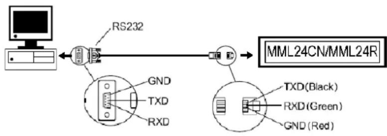
- Plug the RJ45 connector into the RJ45 input of the sign.
- Identify the COM port on the back of your computer. Connect the 9-pin connector to this port. If the 9-pin connector is not connected to the correct port, computer communication to your sign will not work.
7.5. Software Screen
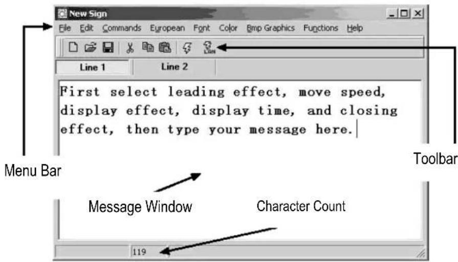
The Toolbar

Open a new Message Window.
Open an existing file.
Save the current message in the Message Window.
Cut the highlighted selection and put it on the clipboard.
Copy the highlighted selection and put it on the clipboard.
Paste the contents of the clipboard.
Send the message in the Message Window to the sign.
Send the message through LAN.
The Menu Bar
File
New open a new window
Open open an existing file
Save save the file currently open
Set Comm set the communication settings
Exit exit the software program
Edit
Cut cut the highlighted selection and put it on the clipboard
Copy copy the highlighted selection and put it on the clipboard
Paste paste the contents of the clipboard onto the active document
Delete remove the selected content from the Message Window
Commands
Leading how the text will appear
Display Effect how the text will display
Display Time how long the message will display
Speed control the leading and closing speed
Closing how the text will disappear
Special insert the TIME, DATE and BEEP
European
| € U00 | ↑ U01 | ↓ U02 | ↑ U03 | ↑ U04 | ↓ U05 | ↓ U06 | ↓ U07 | ↓ U08 | ↑ U09 |
| T U0A | - U0B | + U0C | ↓ U0D | ↑ U0E | ■ U0F | ■ U10 | ■ U11 | ■ U12 | ■ U13 |
| α U14 | β U15 | Γ U16 | Π U17 | Σ U18 | σ U19 | μ U1A | τ U1B | Φ U1C | ≈ U1D |
| Ω U1E | δ U1F | ω U20 | λ U21 | ζ U22 | £ U23 | γ U24 | ¥ U25 | → U26 | ← U27 |
| ι U28 | ◎ U29 | a U2A | ≥ U2B | ε U2C | ∩ U2D | ◎ U2E | Φ U2F | § U30 | ± U31 |
| 2 U32 | 3 U33 | ž U34 | ü U35 | η U36 | ο U37 | ş U38 | ι U39 | o U3A | ≤ U3B |
| ¼ U3C | ½ U3D | κ U3E | ι U3F | à U40 | á U41 | ˆ U42 | ˆ U43 | ˆ U44 | ˆ U45 |
| Ε U46 | ζ U47 | Ε U48 | Ε U49 | Ε U4A | Ε U4B | ι U4C | ι U4D | ι U4E | ι U4F |
| θ U50 | Ñ U51 | Ω U52 | Ω US3 | Ω US4 | Ω US5 | Ω US6 | Ž US7 | θ US8 | Ω US9 |
| ú U5A | ú USB | ü USC | ŷ USD | þ USF | ð USF | á U60 | á U61 | á U62 | á U63 |
| ä U64 | ä U65 | æ U66 | ζ U67 | è U68 | é U69 | é U6A | é U6B | ι U6C | ι U6D |
| ι U6E | ι U6F | δ U70 | ⁿ U71 | ò U72 | ó U73 | ô U74 | ô U75 | ö U76 | … U77 |
| ø U78 | ü U79 | ú U7A | ú U7B | ü U7C | ŷU7D | þ U7E | ŷU7F |
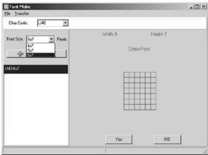
User Font Make
Select the character code (refer to the table above) and select the font size. Click the button to add the item in the list box. Select the item to draw the font.
Click [TRANSFER] [TRANSFER TO SIGN] to update the user font of the sign.
Click [FILE] [SAVE FONT] to save a file.
Recalling the Default Font
Recall the above default European characters to the sign and software.
Font
Select any one of the font styles, European or Greek characters.
Color
Select any one of the listed colours.
Bmp Graphics
Edit Graphic... edit and save your own graphic images and insert them into the Message Window. Refer to the "BMP Graphic Editor".
Functions
Send Message send the current text in the Message Window to the LED display board. Before transferring, select the board's ID (ID which you may set by "Set ID..." function). Also, set which page to transfer to. There are 26 pages in all.
Run Page run a specified page on the LED board
Links Pages to Run link some pages in order to run more than one page, e.g. type A, B and C to run page A, B and C
Set ID set the ID of the LED board
Note: ID00 is used for the global call. If you use more than one sign, connect all the signs
in a network, e.g. from ID01 to ID05. Afterwards, you can send a message to the desired sign entering the individual ID number. Use ID00 to send to all the signs.
Set Clock set the date and time
Delete Page delete specific page information on the sign
Set Brightness set the display's brightness over 4 levels
Display by Schedule schedule a message to be displayed
Delete Page delete some pages in the running messages
Delete Schedule delete some items in the Schedule Table
Delete all delete all the messages
7.6. Software Configuration
- Go to "File", "SetComm".
- Select the COM port.
- Click on "OK" when your settings are complete.
7.7. Sending a Message
Use the "Send Message" icon to transmit the message to the LED board.
In the Message Window, type in a test message, e.g. "WELCOME".
- Click on the icon on the Toolbar to bring up the Message Window.
- Enter the sign ID number and select the page to send your message to. You have pages A to Z available. Each page can be used to store a different message.
- Click on "OK" to send the message to the LED board. If the board did not receive your message, try sending the message again.
7.8.BMP Graphic Editor
Use the BMP Graphic Editor to edit or create graphics of your own. To open this window, click on the "Bmp Graphics" in the Menu Bar and then click on "Edit Graphics".
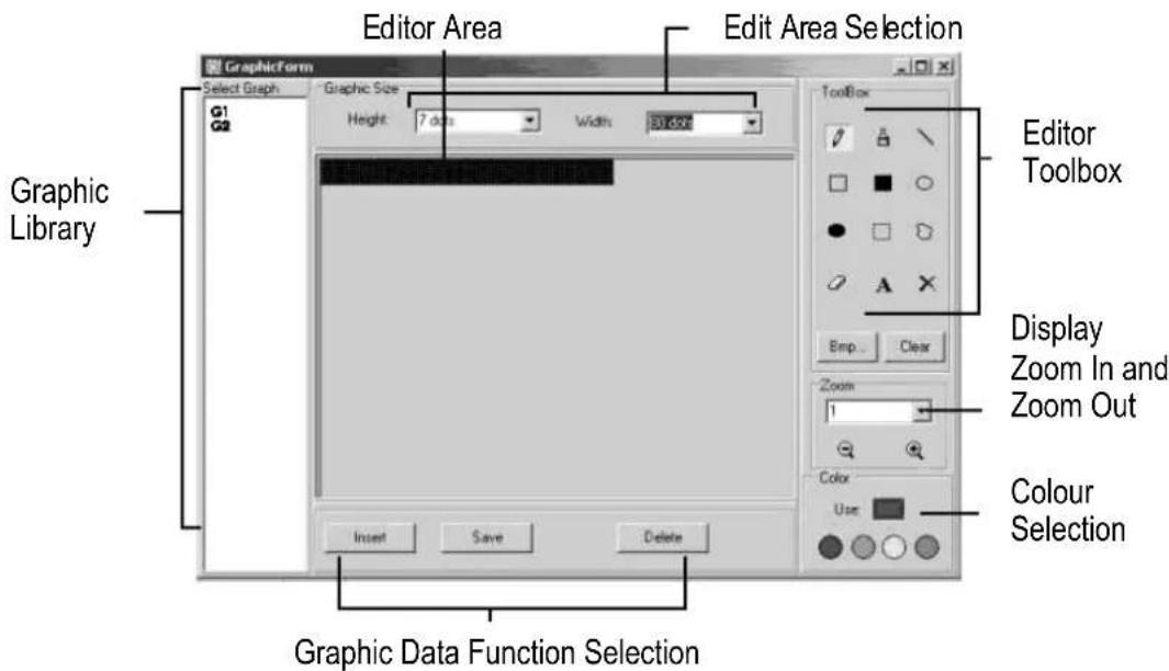
Select a Graphic Window by clicking on any one of the graphics from the "Select Graphic" list. A maximum of 16 graphic pages can be stored.
Color
Select any of the four colours to edit an existing graphic or to create a graphic.
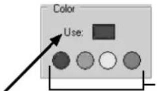
Colours: black, red, green, yellow
Graphic Data Function
Current selected colour
Save save the current graphic displayed in the Graphic Window
Delete delete a graphic from the Graphic Library
Insert insert the current graphic from the Graphic Window into your message
Editor Toolbox

Pen Tool: Click this tool and move the mouse to the Editor Area. Press and Hold down the left button of your mouse and move your mouse to free hand draw.
Brush Tool: Click this tool and move the mouse to the Editor Area. Press and hold down the left button of your mouse and move your mouse to use the brushing function.
Line Tool: Click this tool and move your cursor to the starting point of the line. Move your mouse to the end point of the line while holding down the left button of your mouse. Release the mouse button.
Outline Rectangle Tool: Click this tool. Select the starting point by moving your cursor and holding down the left button of your mouse. Move the mouse at the end point and release the button.
Rectangle Tool: See Outline Rectangle Tool.
Outline Ellipse Tool: See Outline Rectangle Tool.
Ellipse Tool: See Outline Rectangle Tool.
Pointer Tool: Click this tool. Select the Editor Area by pressing and holding down the left button of your mouse. The selected area will be round. Move the area by holding down the left button of your mouse to the desired position. Release the button. Right click to fix.
Polygon Pointer Tool: See Pointer Tool.
Erase Tool: Click this tool. Press and hold down the left button of your mouse to erase the area you want.
Clear Tool: Click this tool and select the colour. Move the cursor to the Editor Area and left click. The whole area will turn into that colour.
Text Tool: Click this tool. Move the cursor into the Editor Area. Left click your mouse and write your text. You can cut and paste your text, select font sizes and text colours. Click the "OK" button to finish. You can move the text to the desired position by dragging the text box.
Clear Function: Left click this button to clear the whole Editor Area.
Bmp File Function: Left click this button to export or import a BMP file.
Display Zoom In and Zoom Out
Select the zoom from 1 to 8, 1 being the smallest.
7.9. LAN Communication
How it Works
The display is first connected to the serial COM port of a computer in the LAN environment which we refer to as the Receiver Slave Computer (RSC). The computer that will actually be transmitting messages to the LED display is
referred to as Transmitting Master Computer (TMC). The TMC will have the display control software installed. It is not necessary to install the software on the RSC. Next step is to set up a "Generic / Text Only" printer driver on the RSC and share it with the TMC. Once the setup is done and a message is created, a simple click on the "Send Via Network" button will bring up the "PRINT" dialog window. Select the "Generic / Text Only" printer and click "OK" and your message will be on its way.
RSC Printer Driver Setup
- Click on "Start", "Settings" and "Printer". The "PRINT" dialog window will appear.
- Double click on the "Add Printer" icon. The "Add Printer Wizard" window will appear.
- Click on "Next". Select "Local Printer" and click on "Next" again.
- Under "Manufacturers", search for "Generic" and click on "Next". If prompted "A driver is already installed to this printer", select "Keep existing driver" and click "Next".
- Select the COM port on the RSC the display will connected to and click on "Next".
- Under "Printer Name", type in the desired name (min. 12 characters long) for the Display Printer Driver. Select "No" to select the printer as the default printer and click "Next".
- Click on "Finish" to complete the setup. Insert the CD or disk in the proper driver if necessary and click "OK".
- Select the printer you've created. Go to "File" and click on "Properties".
- Click on the "Details" tab and click on "Port Settings".
- Make sure the settings below are set accordingly. Click on "OK" when done.
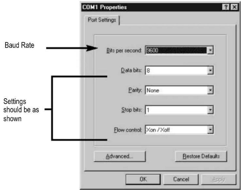
- Click on the "Sharing" tab and click on "Shared As". In the "Share Name" box, type in the "Printer Name" used earlier. Type in a password when desired.
- The RSC Printer Driver setup is now complete.
TMC Printer Driver Setup
- Click "Start", "Settings" and "Printer". The "PRINT" dialog window will appear.
- Double click on the "Add Printer" icon. The "Add Printer Wizard" window will appear.
- Click on "Next". Select "Network Printer" and click "Next".
- Select "No" to print from "MS DOS based programs". Click on "Browse".
-
Double click on the name of the RSC on the network and select the created Display Printer Driver.
-
Click on "OK". Now click on "Next".
- Under "Printer Name", type in the "Printer Name" used earlier.
- Select "No" to select the printer as the default printer and click on "Next".
- Click on "Finish" to complete the setup. Insert the CD or disk in the proper driver if necessary and click "OK".
- The TMC Printer Driver Setup is now complete.
Sending a Message through the LAN
- Start the software and create your message.
- Click on LAN for "Send via Network". Enter the "Sign ID Number" and "Page Number" and click "OK".
- Select the Display Printer Driver from the "Printer Name" box and click "OK".
8. Quick Reference Section
Colour Code Table (MML24CN: A → J; MML24R: A + D)
| Letter | Foreground | Colour | Background |
| A | Red | Black | |
| B | Green | Black | |
| C | Yellow | Black | |
| D | Black | Red | |
| E | Black | Green | |
| F | Black | Yellow | |
| G | Red | Green | |
| H | Green | Red | |
| I | Red/Yellow/Green | Black | |
| J | Random | Black |
Font Size Table
Select a font size and press [FONT] to toggle between the different fonts.
| Letter Character | Font Size |
| A Normal (5 x 7) | |
| B Bold (6 x 7) | |
| D Narrow (4 x 7) |
European Character Table
To display a European character, press the corresponding letter. Press the [EUROP-CHAR] key until the European letter of your choice is reached. Once you see the European letter you wish to use, press any other letter to continue to type your message
| Letter in "PPER CASE" | Foreground Colour | Letter in "OWER CASE" | Foreground Colour |
| A | Ä Å Å Å Å Å Å | a | ã à à à à à æ |
| B | β | c | ç |
| C | Ç | e | é é è |
| D | D | i | íìīi |
| E | É É E E | n | ñ |
| I | ɪlɪli | o | ó ò ò ò ò |
| N | Ñ | p | þ |
| O | Ö O O O O Ø | u | úùū |
| P | þ | y | |
| U Ú U U U | |||
| Y | þ | þ |
y
Special Effects Table
After completing the message editing you can select the leading and closing effect.
| Letter | Type | Effect Description | |
| A L, | T Immediate | Image appears immediately | |
| B L, | T X Open | Image shown from centre and extends to 4 sides | |
| C L, | T | Curtain Up | Image jumps one line from bottom to top |
| D L, | T | Curtain Down | Image jumps one line from top to bottom |
| E L, | T | Scroll Left | Image scrolls from right to left |
| F L, | T | Scroll Right | Image scrolls from left to right |
| G | L, T | V Open | Image shown from centre and opens to the two top corners |
| H L, | T | V Close | Image shown closes to centre |
| I L, | T | Scroll Up | Image scrolls from bottom to top |
| J | L, T | Scroll Down | Image scrolls from top to bottom |
| K L, | T | Hold | Previous screen is kept |
| L | L | Snow | Pixels drop from the top and stack up to build the image |
| M | L | Twinkle | Blank diagonal line scrolls on the image |
| N | L | Block Move | An 8-pixel display block moves from right to left |
| P | L | Random | Random pixels appear to build the image |
| Q | L | Pen Writing | Hello World |
| R | L | Pen Writing Welcome |
L = Leading effect (how the message will appear)
T = Closing effect (how the message will disappear)
Display Effect
A normal
B blinking
C play song 1
D play song 2
E play song 3
Moving Speed
A fast
B medium 1
C medium 2
D slow
Bell Duration
A short
B medium 1
C medium 2
D long
Display Time
0.5s ~ 13s
Date Display Format
DD/MM/YY
Time Display Format
hh/mm
9. Help Section
- Can I control more than one sign from a central location?
Set different ID addresses. The software will allow you to control up to 255 signs.
How do I remove the demo message on the sign?
The demo message is permanently programmed into the sign and is designed to run automatically when there are no other messages programmed by the user. When you program a message onto a page, the demo message will no longer show.
How much text can I program onto one page?
You can program up to 210 characters per page. There are 26 pages and 16 graphic pages.
- Will I lose my messages after I remove the power from the sign?
No, there is a built-in battery.
- After unplugging the LED board, I lose TIME and DATE settings. Why?
The battery on the CPU is gone. Replace with a battery with the same specifications.
I plugged in the sign but nothing appears.
Unplug the power to the LED board and plug it in again. Make sure the power adapter is firmly plugged into the LED board. Try using another wall outlet. Try resetting the system.
- The sign does not show any message after setting the display by schedule.
Clear the display by schedule and reset the system.
- The software is not communicating with the sign.
Refer to sections "Setup" and "Sending a Message". Do not extend the 9-pin connection cable with another cable.
- I receive an "Open COM Error".
This means the COM port you selected is not available or being used by an internal device in your computer. Please refer to your computer's user manual or contact the computer's manufacturer for more information.
- My laptop computer does not have any COM ports and only supports USB devices.
Some newer laptops do not have COM ports and only support USB devices (refer to your computer's manual to check). You will need to purchase a USB SERIAL ADAPTER, a device that will convert one of your available USB ports into a working COM port. However, Velleman do not guarantee that this device will work with all laptops due to other devices installed by the user and varying manufacturers' equipment. Contact the laptop's manufacturer directly for questions regarding installation operation.
10. Technical Specifications
Digits 7 x 120 dots (5mm)
Display Area 910 x 55mm
Pixel Pitch 7.62mm
Display Time 0.5 to 13s
Viewing Distance 40m
Viewing Angle 160^
Power Supply
100~240VAC ~ 24VDC / 1.5A (adapter incl.) (MML24CN)
100-240VAC 12VDC / 2.5A (adapter incl.) (MML24R)
For more info concerning this product, please visit our website www.velleman.eu.
The information in this manual is subject to change without prior notice.
MML24CN / MML24R - VEELKLEURIGE LICHTKRANT
Delete all wis alle boodschappen
Rectangle Tool: Zie Outline Rectangle Tool.
Outline Ellipse Tool: Zie Outline Rectangle Tool.
Ellipse Tool: Zie Outline Rectangle Tool.
Polygon Pointer Tool: Zie Pointer Tool.
Commands (Commandes)
| € U0U | ↑ U01 | ↓ U02 | ↑ U03 | ↑ U04 | ↓ U05 | ↓ U06 | ↓ U07 | ↓ U08 | ↑ U09 |
| T U0A | - U0B | ↑ U0C | ↓ U0D | ↑ U0E | ■ U0F | ■ U10 | ■ U11 | ■ U12 | ■ U13 |
| α U14 | β U15 | Γ U16 | Π U17 | Σ U18 | σ U19 | μ U1A | τ U1B | Ω U1C | ≈ U1D |
| Ω U1E | δ U1F | ∞ U20 | × U21 | ∅ U22 | £ U23 | δ U24 | ¥ U25 | → U26 | ← U27 |
| ι U28 | ◎ U29 | a U2A | ≥ U2B | ε U2C | ∩ U2D | ◎ U2E | Φ U2F | § U30 | ± U31 |
| 2 U32 | 3 U33 | ž U34 | ü U35 | η U36 | ε U37 | § U38 | ι U39 | o U3A | ≤ U3B |
| ¼ U3C | ½ U3D | π U3E | ü U3F | ˆ U40 | ˆ A U41 | ˆ A U42 | ˆ A U43 | ˆ A U44 | ˆ A U45 |
| Ε U46 | Ε U47 | Ε U48 | Ε U49 | Ε U4A | Ε U4B | Ε U4C | Ε U4D | Ε U4E | Ε U4F |
| θ U50 | Ñ U51 | Ø U52 | Ø U53 | Ø U54 | Ø U55 | Ø U56 | Ž U57 | θ U58 | Ü U59 |
| Ü U5A | Ü U5B | ü U5C | þ U5D | þ U5E | þ U5F | þ U60 | á U61 | ˆ A U62 | ˆ A U63 |
| ä U64 | æ U65 | æ U66 | ζ U67 | è U68 | è U69 | è U6A | è U6B | ι U6C | ι U6D |
| ˆ U6E | ˆ U6F | ˆ Ω U70 | ˆ N U71 | ˆ Ω U72 | ˆ Ω U73 | ˆ Ω U74 | ˆ Ω U75 | ö U76 | ... U77 |
| Ø U78 | Ø U79 | ˆ U7A | ˆ U7B | ˆ U7C | ψ U7D | β U7E | ˆ ψ U7F |
4. Programar differentes characteres
DisplaygroBe 910x55mm
Pixelgroße 7.62mm
Graphic Data Function
Velleman® Service and Quality Warranty
Velleman® has over 35 years of experience in the electronics world and distributes its products in more than 85 countries.
All our products fulfil strict quality requirements and legal stipulations in the EU. In order to ensure the quality, our products regularly go through an extra quality check, both by an internal quality department and by specialized external organisations. If, all precautionary measures notwithstanding, problems should occur, please make appeal to our warranty (see guarantee conditions).
General Warranty Conditions Concerning Consumer Products (for EU):
All consumer products are subject to a 24-month warranty on production flaws and defective material as from the original date of purchase.
replacement of the article is impossible, or if the expenses are out of proportion.
You will be delivered a replacing article or a refund at the value of 100% of the purchase price in case of a flaw occurred in the first year after the date of purchase and delivery, or a replacing article at 50% of the purchase price or a refund at the value of 50% of the retail value in case of a flaw occurred in the second year after the date of purchase and delivery.
Not covered by warranty:
- all direct or indirect damage caused after delivery to the article (e.g. by oxidation, shocks, falls, dust, dirt, humidity...), and by the article, as well as its contents (e.g. data loss), compensation for loss of profits;
- frequently replaced consumable goods, parts or accessories such as batteries, lamps, rubber parts, drive belts... (unlimited list);
- flaws resulting from fire, water damage, lightning, accident, natural disaster, etc. ...
- flaws caused deliberately, negligently or resulting from improper handling, negligent maintenance, abusive use or use contrary to the manufacturer's instructions; damage caused by a commercial, professional or collective use of the article (the warranty validity will be reduced to six (6) months when the article is used professionally);
- damage resulting from an inappropriate packing and shipping of the article;
- all damage caused by modification, repair or alteration performed by a third party without written permission by Velleman®.
Articles to be reaied must be delivered to your Velleman dealer, solidly packed (preferably in the original packaging), and be completed with the original receipt of purchase and a clear flaw description. - Hint: In order to save on cost and time, please reread the manual and check if the flaw is caused by obvious causes prior to presenting the article for repair. Note that returning a non-defective article can also involve handling costs.
- Repairs occurring after warranty expiration are subject to shipping costs.
The above conditions are without prejudice to all commercial warranties.
The above enumeration is subject to modification according to the article (see article's manual).
- To all residents of the European Union
- Important environmental information about this product
- Remote Control
- Getting started by Remote Control
- Programming Alternate Characters
- Attention-getting Features
- Advanced Features
- Software
- PC system requirements
- USB RS232 Converter
- USB RS232 Converter Serial Interface
- Software Installation
- Setup
- Software Screen
- The Toolbar
- The Menu Bar
- File
- Edit
- Commands
- European
- User Font Make
- Recalling the Default Font
- Font
- Color
- Bmp Graphics
- Functions
- Software Configuration
- Sending a Message
- 7.8.BMP Graphic Editor
- Graphic Data Function
- Editor Toolbox
- Display Zoom In and Zoom Out
- LAN Communication
- RSC Printer Driver Setup
- TMC Printer Driver Setup
- Quick Reference Section
- Font Size Table
- European Character Table
- Special Effects Table
- Display Effect
- Moving Speed
- Bell Duration
- Display Time
- Date Display Format
- Time Display Format
- Help Section
- Technical Specifications
- MML24CN / MML24R - VEELKLEURIGE LICHTKRANT
- Commands (Commandes)
- Programar differentes characteres
- Velleman® Service and Quality Warranty
- General Warranty Conditions Concerning Consumer Products (for EU):
- Not covered by warranty:
- The above enumeration is subject to modification according to the article (see article's manual).
Brand : VELLEMAN
Model : MML24R
Category : Light panel