
MX418DC - Microphone SHURE - Free user manual and instructions
Find the device manual for free MX418DC SHURE in PDF.
| Microphone Type | Electret condenser, miniature, gooseneck |
| Operating Principle | Condenser microphone (electret capsule) |
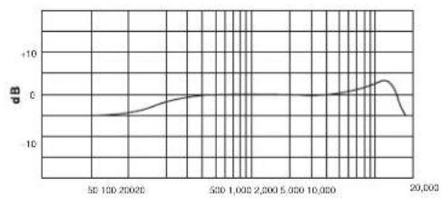
| Frequency Response | 50 to 17,000 Hz |
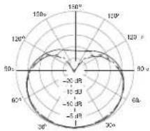
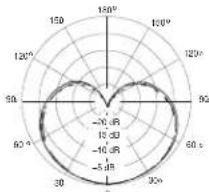
| Polar Pattern (depends on capsule) | Cardioid (MX418D/C) or Supercardioid (MX418D/S) |
| Nominal Output Impedance | 150 Ω (180 Ω actual) |
| Sensitivity (1 kHz, open circuit) | Cardioid: -34 dBV/Pa (21 mV); Supercardioid: -33 dBV/Pa (24 mV) |
| Maximum Sound Level (1 kHz, 1% THD, 1 kΩ load) | Cardioid: 123 dB SPL; Supercardioid: 122 dB SPL |
| Equivalent Output Noise (A-weighted) | Cardioid: 29 dB SPL; Supercardioid: 28 dB SPL |
| Signal-to-Noise Ratio (94 dB SPL at 1 kHz) | Cardioid: 65 dB; Supercardioid: 66 dB |
| Dynamic Range (1 kΩ load at 1 kHz) | 94 dB |
| Common Mode Rejection (10 Hz to 100 kHz) | 45 dB minimum |
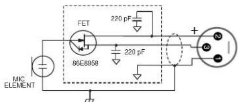
| Polarity | Positive acoustic pressure on diaphragm → positive voltage on pin 2 relative to pin 3 |
| Power Supply | Phantom 11 to 52 V DC, 2.0 mA |
| Net Weight (MX418D) | 0.82 kg (1.82 lb) |
| Gooseneck Length | 457 mm (18 in) |
| Fixed Cable Length | 3 m (10 ft) |
| Output Configuration | Active balanced (XLR 3-pin) |
| Mute Button | Programmable (quick-touch or push-to-talk/push-to-mute) with LED indicator |
| Logic Terminals | LED input (orange, 5 V), MUTE output (white, TTL), logic ground (green) |
| Mute Button Attenuation | ≥ 50 dB |
| Supplied Accessories | Snap-fit foam windscreen (1 supplied) |
| Optional Accessories | Spherical windscreen A99WS, metal windscreen A412MWS, special logic cable (95B2509) |
| Replacement Parts | Capsules: R183B (omnidirectional), R184B (supercardioid), R185B (cardioid) |
| Certification | CE, compliant with EN55103-1:1996 and EN55103-2:1996 |
| Cleaning | Use a soft dry cloth. Protect from moisture. |
Frequently Asked Questions - MX418DC SHURE
User questions about MX418DC SHURE
0 question about this device. Answer the ones you know or ask your own.
Ask a new question about this device
Download the instructions for your Microphone in PDF format for free! Find your manual MX418DC - SHURE and take your electronic device back in hand. On this page are published all the documents necessary for the use of your device. MX418DC by SHURE.
USER MANUAL MX418DC SHURE
Shure Microflex® MX400D Series microphones are miniature electret condenser gooseneck microphones with a desktop base and a 3 m (10 ft.) cable. Desktop base allows microphones to be used in multi-purpose rooms where quick setup is required, or where permanent installation is impractical.
Features
- Wide dynamic range and frequency response for accurate sound reproduction
- Interchangeable cartridges that provide a choice of polar pattern for each application
- Programmable mute button and LED indicator
- Logic input and output terminals for remote control or use with automatic microphone mixers
- Balanced, transformerless output for increased immunity to noise over long cable runs
RF filtering
MX400 Series Model Variations
MX400 microphones are available with 305 mm (12 in.) or 457 mm (18 in.) goosenecks.
" S " models include a mute button and LED.
- "D" models include a desktop base with programmable mute button and LED and logic input and output.
- "SE" models feature a surface mount flange with side-exit cable.
The polar pattern of the included cartridge is indicated by a model number suffix:
C Cardioid
/S Supercardioid
/N Cartridge not included
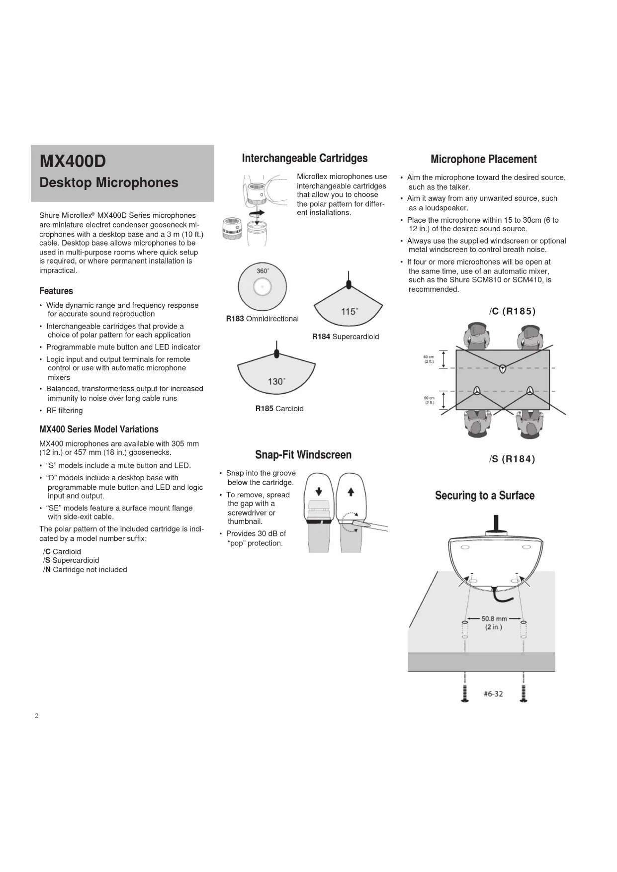
Interchangeable Cartridges
Microflex microphones use interchangeable cartridges that allow you to choose the polar pattern for different installations.
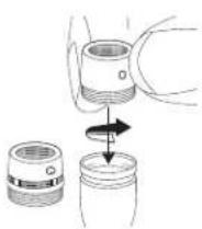
R183 Omnidirectional
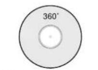
R184 Supercardioid
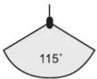
R185 Cardioid
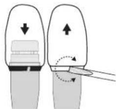
Snap-Fit Windscreen
- Snap into the groove below the cartridge.
To remove, spread the gap with a screwdriver or thumbnail. - Provides 30 dB of "pop" protection.
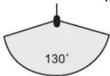
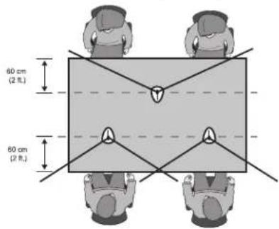
Microphone Placement
- Aim the microphone toward the desired source, such as the talker.
- Aim it away from any unwanted source, such as a loudspeaker.
- Place the microphone within 15 to 30cm (6 to 12 in.) of the desired sound source.
Always use the supplied windscreen or optional metal windscreen to control breath noise.
If four or more microphones will be open at the same time, use of an automatic mixer, such as the Shure SCM810 or SCM410, is recommended.
/C (R185)
/S (R184)
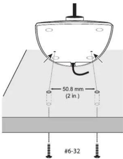
Securing to a Surface
DIP Switches
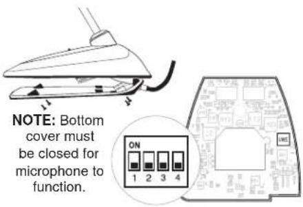
Use the DIP switches to configure logic settings and mute button behavior.
The DIP switches are covered with a piece of clear tape at the factory. Remove tape to modify the switch settings.
| OFF (factory default) | ON | |
| 1 M | Momentary Toggle | |
| 2 P | Push-to-mute Push-to-talk | |
| 3 M | ute button enabled, LED illuminates when mic is active | Disable mute button (microphone always on), logic controls LED |
| 4 -- -- | ||
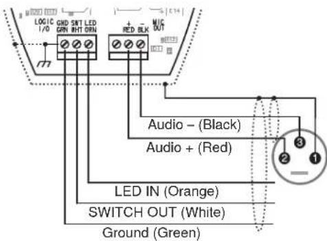
Wiring Diagram
NOTE: Audio and logic ground are connected at microphone base.
Mute Button Configuration
Use DIP switches 1 and 2 to configure the mute button, as follows.
Be sure to set DIP switch 3 off (factory default) so that the mute button controls audio from the microphone.
| Switch Function DIP Switch Setting | |
| Momentary: push-to-mute(as shipped). | ON1 2 3 4 |
| Momentary: push-to-talk | ON1 2 3 4 |
| Toggle: (Push On/PushOff): Mic is active whenpowered on | ON1 2 3 4 |
| Toggle: (Push On/PushOff): Mic is mute whenpowered on | ON1 2 3 4 |
Connecting to an Automatic Mixer
Use these settings if connecting the microphone to an automatic mixer or other device that mutes audio and controls the LED.
- Connect logic leads to the automatic mixer. Connect the LED IN to the gate output to illuminate the LED when that channel is gated on.
- Set DIP switch 3 on. This disables the mute button (the microphone passes audio regardless of whether the button is pressed or not).
- Set DIP switch 1 to configure how the mute button sends SWITCH OUT logic:

Momentary:
push = 0 Vdc,
release = 5 Vdc

Toggle:
initial = 5 Vdc,
push = 0 Vdc
Logic Wiring
Green (LOGIC GROUND): Connects to the logic ground of an automatic mixer, switcher, or other equipment.
Orange (LED IN): Set DIP switch 3 on to use LED IN. When shorted to LOGIC GROUND, the LED turns on.
White (SWITCH OUT): Provides TTL logic (0 Vdc or 5 Vdc) in response to the mute button. Set DIP switch 1 for momentary or toggle. When phantom power is applied, logic initializes high (5 Vdc). DIP switch 2 has no effect on SWITCH OUT.
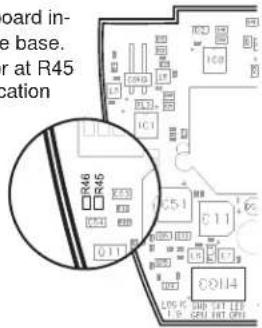
Changing SWITCH OUT to Always Momentary
Use the following modification in situations where your logic interface requires momentary closure of the SWITCH OUT, but you want the mute button to toggle the microphone (DIP switch 1 ON, 3 OFF):
- Access the circuit board inside the microphone base.
- Remove the resistor at R45 and reinstall it at location R46.
Specifications
Type
Condenser (electret bias)
Frequency Response
50-17000 Hz
Polar Pattern
MX412D/C, MX418D/C: Cardioid
MX412D/S, MX418D/S: Supercardioid
Output Impedance
EIA Rated at 150Ω (180Ω actual)
Output Configuration
Active balanced
Sensitivity (at 1 kHz, open circuit voltage)
Cardioid: -34 dBV/Pa (21 mV)
Supercardioid: -33 dBV/Pa (24 mV)
1 Pascal=94 dB SPL
Maximum SPL (1 kHz at 1% THD, 1 kΩ load)
Cardioid: 123 dB
Supercardioid: 122 dB
Equivalent Output Noise (A-weighted)
Cardioid: 29 dB SPL
Supercardioid: 28 dB SPL
Signal-to-Noise Ratio (referenced at 94 dB
SPL at 1 kHz)
Cardioid: 65 dB
Supercardioid: 66 dB
Dynamic Range (1 kΩ load at 1 kHz)
94dB
Common Mode Rejection (10 Hz to 100 kHz)
45 dB minimum
Preamplifier Output Clipping Level (1% THD) -6 dBV (0.5 V)
Polarity
Positive sound pressure on diaphragm produces positive voltage on pin 2 relative to pin 3 of output XLR connector.
Net Weight
MX412D:0.81 kg (1.80 lbs)
MX418D:0.82 kg (1.82 lbs)
Packaged Weight
MX412D: 1.63 kg (3.62 lbs)
MX412D: 1.64 kg (3.64 lbs)
Logic Connections
LED IN: Active low (≤ 1.0V) ,TTL compatible.
Absolute maximum voltage: -0.7V to 50V.
LOGIC OUT: Active low (≤ 1.0V) sinks up to
20mA, TTL compatible. Absolute maximum
voltage: -0.7V to 50V (up to 50V through 3k
Mute Switch Attenuation
-50 dB minimum
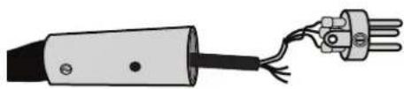
Cable
3 m (10 ft) attached cable with shielded audio pair terminated at a 3-pin male XLR and three unterminated conductors for logic control
Environmental Conditions
Operating Temperature: -18-57 °C (0-135 °F)
Storage Temperature: -29-74 °C (-20-165 °F)
Relative Humidity: 0–95%
Power Requirements
11-52 Vdc phantom, 2.0 mA
Furnished Accessories
Snap-fit Foam Windscreen (1 furnished, 4 in replacement kit)
RK412WS
Optional Accessories
Foam Ball Windscreen A99WS
Metal Locking Windscreen A412MWS
Custom Logic Cable (specify length) 95B2509
Replacement Parts
Omnidirectional Cartridge (Black) R183B
Supercardioid Cartridge (Black) R184B
Cardioid Cartridge (Black) R185B
CERTIFICATION
Eligible to bear CE Marking. Conforms to European EMC Directive 2004/108/EC.Meets Harmonized Standards EN55103-1:1996 and EN55103-2:1996, for residential (E1) and light industrial (E2) environments.
The Declaration of Conformity can be obtained from:
Authorized European representative:
Shure Europe GmbH
Headquarters Europe, Middle East & Africa
Department: EMEA Approval
Jakob-Dieffenbacher-Str. 12
75031 Eppingen, Germany
Phone: +49 7262 92 49 0
Fax: +49 7262 92 49 11 4
Capsules interchangeable

MX412D: 1.63 kg (3.62 lbs)
MX412D: 1.64 kg (3.64 lbs)
Connexions logiques
75031 Eppingen, Germany
Phone: +49 7262 92 49 0
Fax: +49 7262 92 49 11 4
MX412D: 1.63 kg (3.62 lbs)
MX412D: 1.64 kg (3.64 lbs)
Logikanschlusse
11-52 V DC Phantomspeisung, 2,0 mA
Headquarters Europe, Middle East & Africa
75031 Eppingen, Germany
Tel: +49 7262 92 49 0
Fax: +49 7262 92 49 11 4
MX412D: 1.63 kg (3.62 lbs)
MX412D: 1.64 kg (3.64 lbs)
Conexiones lóngicas
75031 Eppingen, Germany
Phone: +49 7262 92 49 0
Fax: +49 7262 92 49 11 4
MX412D: 1.63 kg (3.62 lbs)
MX412D: 1.64 kg (3.64 lbs)
Collegamenti logici
75031 Eppingen, Germany
Phone: +49 7262 92 49 0
Fax: +49 7262 92 49 11 4
MX412D: 1.63 kg (3.62 lbs)
MX412D: 1.64 kg (3.64 lbs)
日夕
LEDIN:艾卡TIP口一(1.0V以下)TTL对応。絶対
最大電圧:0.7V~50V
75031 Eppingen, Germany
Phone: +49 7262 92 49 0
Fax:+4972629249114
E-1:info@shure.de

SARCIDIC KASIKIDIC SARCIDIC KASIKIDIC SARCIDIC
250Hz 500Hz 1000Hz
250Hz 6400Hz 1000Hz
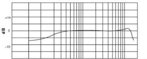
5010020020 5001,0002,0005.00010.000 20,000
Hz
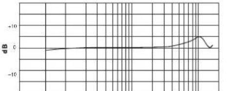
SUPERCARDOTLE SUPERCARDOTLE SUPERCARDOTLE SUPERCARDOTLE
5001,0002,0005.00010.0005510020020 20,000
Hz
CONSTRUCTION: CMIDFRETICENCE:ALL RIGHTS INGEN: CMIDRECENTRAL
United States, Canada.
Latin America, Caribbean:
Shure Incorporated
5800 West Touhy Avenue
Niles, IL 60714-4608 USA
Europe, Middle East, Africa
Shure Europe GmbH
Jakob-Dieffenbacher-Str. 12,
75031 Eppingen, Germany
Phone:+49-7262-92490
Fax: +49-7262-9249114
22/F, 625 King's Road
North Point, Island East
Hong Kong
Phone:+852-2893-4290
Fax: +852-2893-4055
- Features
- MX400 Series Model Variations
- Interchangeable Cartridges
- Snap-Fit Windscreen
- Microphone Placement
- DIP Switches
- Wiring Diagram
- Mute Button Configuration
- Connecting to an Automatic Mixer
- Logic Wiring
- Changing SWITCH OUT to Always Momentary
- Specifications
- Furnished Accessories
- Optional Accessories
- Replacement Parts
- CERTIFICATION
- Capsules interchangeable
- Connexions logiques
- Logikanschlusse
- Collegamenti logici
Brand : SHURE
Model : MX418DC
Category : Microphone