
Project 1500 - Winch Lofrans - Free user manual and instructions
Find the device manual for free Project 1500 Lofrans in PDF.


| Product Type | Electric windlass for boat |
| Brand | Lofrans |
| Model | Project 1500 |
| Weight | 32 kg |
| Nominal Power | 1500 W (S2 duty – 11 minutes) |
| Supply Voltage | 12 V DC or 24 V DC |
| Current Consumption | 90-130 A (12 V) / 50-80 A (24 V) |
| Recovery Speed | 18 to 24 m/min |
| Maximum Instant Pull | Approximately 1500 kg |
| Compatible Chain Sizes | 8 mm, 10 mm, 12 mm; 5/16", 3/8", 7/16" HT/BBB |
| Compatible Rope Diameter | 16-20 mm (5/8"-3/4") |
| Motor Protection Rating | IP 66 |
| Gypsy Material | Nickel-plated steel |
| Base Bearing Material | AISI 440 stainless steel |
| Rope Drum | Independent from the gypsy |
| Manual Emergency Override | Yes (with crank) |
| Finish | Standard chrome-plated |
| Safety | Lofrans magnetic-thermal switch recommended; manual clutch; chain and rope must be secured to a fixed point |
| Maintenance | Rinse with fresh water after use; grease the clutch cones and main shaft thread; check electrical terminals; replace external seals; drain gearbox and refill with SAE 90 oil |
| Warranty | 2 years (subject to registration within 30 days) |
| Recommended Battery Capacity | 250 Ah (12 V) / 150 Ah (24 V) |
| Power Cable Cross-section | 50 mm² (1 AWG) for 12 V / 35 mm² (2 AWG) for 24 V |
Frequently Asked Questions - Project 1500 Lofrans
User questions about Project 1500 Lofrans
0 question about this device. Answer the ones you know or ask your own.
Ask a new question about this device
Download the instructions for your Winch in PDF format for free! Find your manual Project 1500 - Lofrans and take your electronic device back in hand. On this page are published all the documents necessary for the use of your device. Project 1500 by Lofrans.
USER MANUAL Project 1500 Lofrans
MANUEL D'INSTRUCTIONS
GEBRAUCHSANWEISUNG
Thank you for choosing Lofrans . The Project 1500 is the new Lofrans windlass , designed for boat from 12 up to 18 mts length . Listed below are the technical features :
Chromed Bronze finish as standard
Nominal power with S2 parameter 11 minutes: 1500W
Peak power with S2 parameter 1 minute : 2000W
Electric motor waterproof IP 66 degree
- Nicked chain gipsy
- Rope and chain management with 8-10-12-5/16"HT-5/16"BBB--3/8"HT-7/16"HT chain and diameter 16-18-20-5/8"-3/4" rope
Main shaft in stainless steel AISI 431
- Base bearing in stainless steel AISI 440
- Independent drum from gipsy
- Manual override equipped
Haulage speed: from 18 up to 24 mt/min - Ampere load: from 90-130 A (12V), from 50-80 A (24V)
Max pull measured with dynamometer : Kgs 1500 approx
Weight:Kgs 32
SAFETY INFORMATION
This product is not designed as a strong point to fasten your anchor rode. Fast the anchor rode to a strong point such as mooring cleat or similar.
The vessel's engine should always be running and used to assist in the recovery of the ground tackle.
Always install the properly rated circuit breaker to protect the electric circuit and the motor from overheating and damage.
Always turn off the main switch when the windlass is not in use to prevent accidental engagement.
Always keep hands and feet clear of an operating windlass. If a jam occurs turn the windlass off at the main switch before clearing the anchor rode.
- Do not use the windlass for different purposes it was designed for.
WINDCLASS WIRING MINIMUM REQUIREMENTS
Below there are the requirements for all the components of the windlass electric plant depending from the motor nominal power .
| 1500 W 12V 1500 W 24V | ||
| A-Battery capacity 250 Ah 150 Ah | ||
| B-Power cables size 50 mm² - 1 AWG 35 mm² - 2 AWG | ||
| C-Loftrans Circuit breaker (slow time/current curve) 125 A 70 A | ||
| Fuse 5 A 5 A | ||
| Control wires size 1,5 mm² - 14 AWG 1,5 mm² - 14 AWG |
NOTES
A. Battery of lower capacity decrease the windlass performances and are rapidly subjected to wear and tear.
B. This size must be increased when the length of the positive plus the negative cables are more than 25 mts. Use marine grade tinned copper wire.
C. The Loftrans circuit breaker protects the power line from short circuit and the windlass motor in case of overheating. It must be kept dry and installed in accessible place to be prompty reactivated when it trips. It can be also used to isolate the windlass from the remote controls as we strongly suggest to avoid accidental engagement.
All the switches must be wired in parallel. We strongly recommend to have a minimum of two switches to operate the windlass in case one of them gets damage.
All Loftrans equipment is CE approved.
INSTALLATION GENERAL REQUIREMENTS
Proper installation of the windlass is critical and these essential conditions listed below need be fully satisfied :
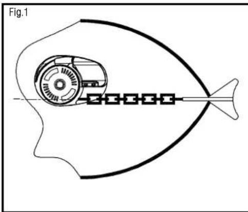
Fig.1 The gipsy of the windlass must be in line with the bow roller.
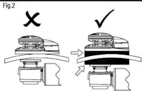
Fig.2 The deck must be flat. The structure of the boat must be adequate to the load that the windlass is able to pull. If necessary reinforce the deck with a backing pad to spread the stress.
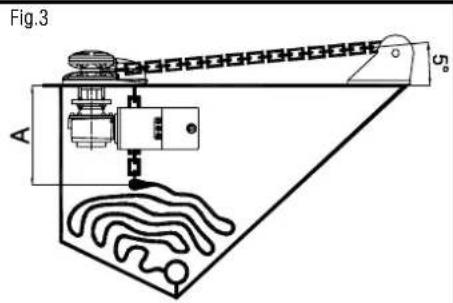
Fig.3 When determining the position of the windlass, it is critical to locate it directly above the deepest area of the chain locker. As the chain falls into the chain locker, it must be maximized because when the chain is stored. The chain tends to gather in the shape of a pyramid, which reduces the available space. If the chain pyramid falls, then overlaps may occur, resulting in jams. The deeper the locker, the less likely this will occur. You must have a minimum of A = 12 between the underside of the deck and the top of the heaped chain. The chain locker shape is really important to limit the pyramid problem. The chain coming from the bow roller can be inclined up to 5 degrees.
INSTALLATION PROCEDURE
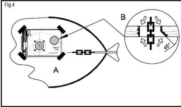
Fig.4 Carefully position the template provided to the deck . Mark and drill the holes as indicated (see Fig.A). The forward , leading edge of the chain hole should be dressed with a 45^ degree angle. A drum rasp or Dremil Tool will be helpful. Sand smooth all edges and seal (see Fig.B). Clean the deck area and position the deck gasket supplied.
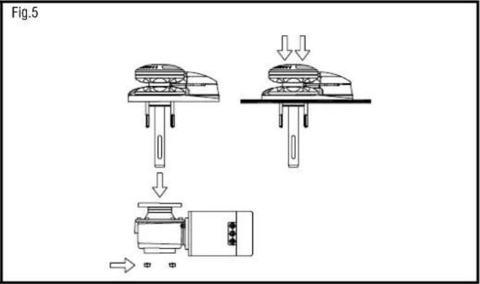
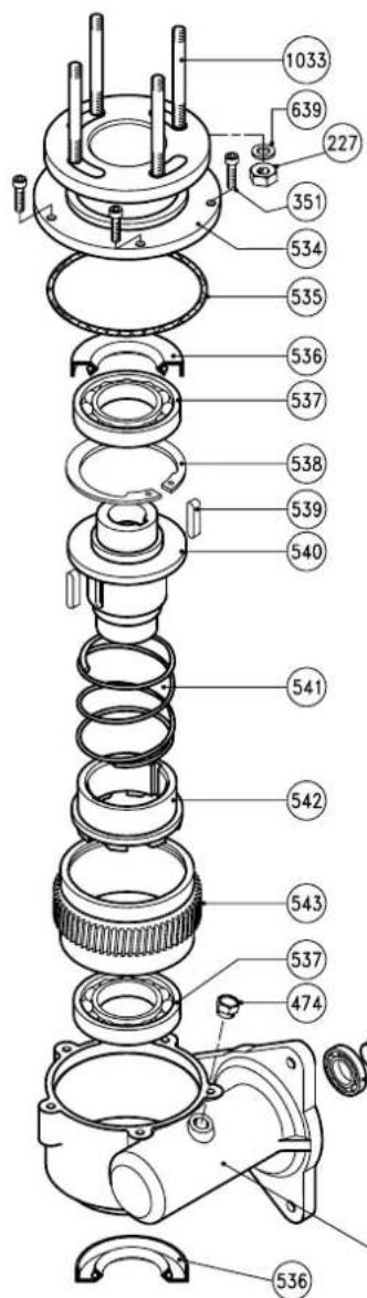
Fig.5 Loosen the 4 hex nuts (227) to separate the topworks from the gearbox and motor. Position the topworks the deck aligning the gasket properly.
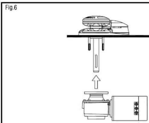
Fig.6 Join the gearbox to the windlass topworks by inserting the key (450) of the main shaft into the key way of the gearbox. Align the motor away from the chain pipe.
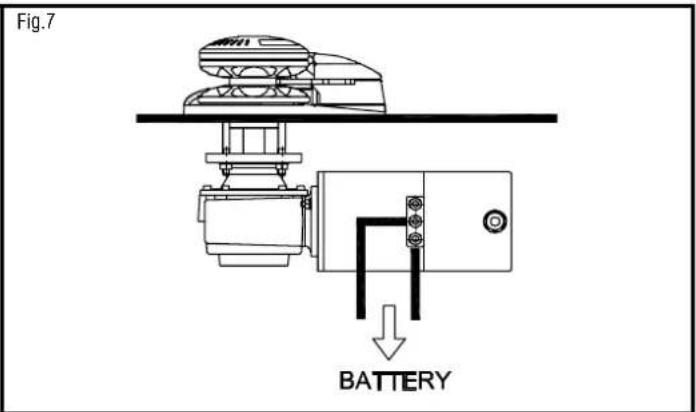
Fig.7 Fasten a washer, lock washer and hex nut to the remaining deck studs. Tighten all hardware properly. Connect the cables from the battery to the electric motor as shown in the electric diagram.
TEST PROCEDURE
ATTENTION ! DO NOT OPERATE THE WINDLASS WITHOUT THE ROPE-CHAIN INTO THE GIPSY TO AVOID TO DAMAGE THE PART 998 (FINGER)
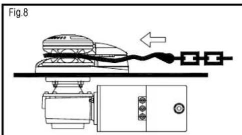
Fig.8 Introduce the rope-chain into the gipsy . Please take care to keep hands and feet away of the incoming rope-chain.
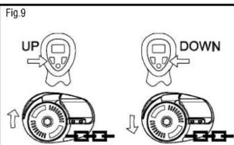
Fig.9 Tn on the remote contol. Operate the UP switch. The chain will be recovered. Reise the UP switch.Operate the DOWN switch. The chain will be released. If the windlass runs in wrong direction change over the UP and DOWN wires at the control box.
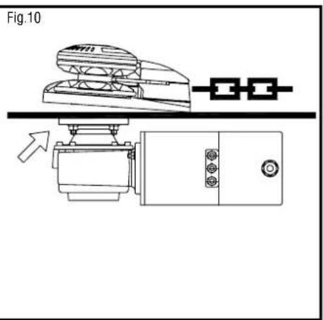
Fig.10 After using the windlass, we strongly recommend that the nuts are checked again to ensure they are well tightened.
The basic operations you need to know are lowering and raising the anchor by electric motor. This product is cone clutch-equipped which allows to you to lower the anchor without using the electric motor. Lofrans strongly recommend to use the chain stopper in conjunction with this windlass. The chain stopper is a device which is normally installed on the boat and will keep your chain in place on deck. It must be used to secure the anchor after anchoring.
OPERATION FIRST THEN ...
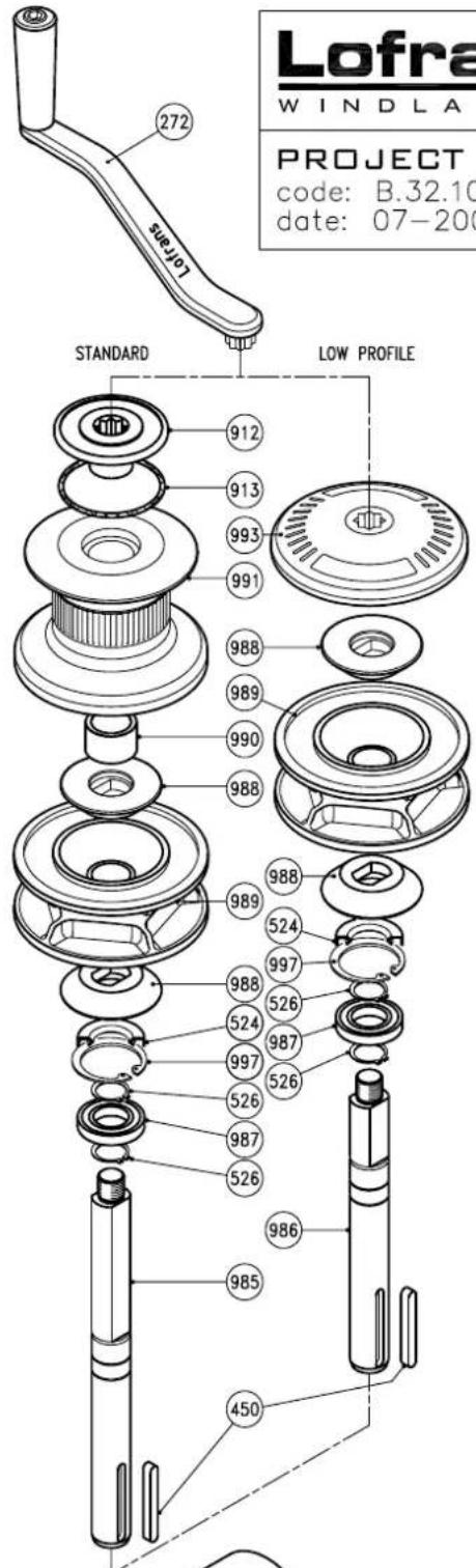
| 1. USE OF THE CLUTCH ON THE LOW PROFILE MODEL | - | To disengage the clutch insert the handle (272) into the star-shaped slot on the gipsy cap (993) and loosen it. To engage the clutch again tight the gipsy can until you cannot move the handle any more. Anchor and/or chain provide resistance during the tightening. |
| 2. USE OF THE CLUTCH ON THE STANDARD MODEL | - | To disengage the clutch insert the handle (272) supplied into the clutch nut (912) and loosen it. To engage the clutch tighten it until you cannot move the handle any more. |
| 3. LOWERING THE ANCHOR BY THE ELECTRIC MOTOR | · Disengage the Chain stopper · Check if the Clutch is engaged · Turn On the Circuit breaker | Simple push the button DOWN. You will have always a perfect control of the operation, which can be interrupted any moment by releasing the button DOWN. |
| 4. AFTER ANCHORING | · Engage the Chain stopper · Engage the Clutch · Turn Off the Circuit breaker | If you have all chain, reduce the windlass load by engaging the chain stopper. If using a combination of rope and chain, fix the rope to a strong point such as a cleat. |
| 5. RAISING THE ANCHOR | · Disengage the Chain stopper · Check if the Clutch is engaged · Turn On the Circuit breaker | Start the engine of the boat. Push the button UP while with the boat at minimum speed going towards the anchoring point. Do not use the windlass to pull the boat to the anchor. Release the button UP to stop the operation. Pay attention to the speed of the anchor, which may damage the bow of your boat. In the event that the anchor becomes stranded and the Loftrans circuit breaker trips, wait several minutes before re-setting and try once more. Should the circuit breaker trip again, we suggest to fix the rope or chain to a cleats and then use the boat engine to break the anchor loose. |
| 6. DURING THE NAVIGATION | · Engage the Chain stopper · Engage the Clutch · Turn Off the Circuit breaker | Windlass must not be used as the sole means of securing the anchor to the bow fitting. Anchors should be independently secured to prevent accidental release. Use a chain stopper or a lanyard to do that. |
| 7. LOWERING THE ANCHOR BY THE CLUTCH | · Disengage the Chain stopper · Turn Off the Circuit breaker | Disengage the clutch. As the chain falls, it can be controlled by the clutch handle. At the end of the operation engage the clutch. |
| 8. USE THE DRUM | · Engage the Chain stopper · Turn On the Circuit breaker | Disengage the clutch. Turn clockwise around the drum with 2-3 laps of rope. Keep the end of rope. Push the button UP, recovering the rope at the same time. |
| 9. USE OF THE MANUAL EMERGENCY | · Disengage the Chain stopper · Engage the Clutch · Turn Off the Circuit breaker | Insert the handle into the star-shaped slot (912 or 993) and turn it clockwise to exceed the gearbox spring strength (541). The stress will be hard in case of deep anchoring. |
MAINTENANCE PROGRAM
Below are indicated the operations and the period we consider essential to got the best efficiency and performance of your anchor windlass.
A. Clean all the outer surfaces and the hidden points with fresh water and remove the salt layer.
B. Grease the outer rotation parts . Particularly the main shaft thread and the clutch cones. Check for evidences of corrosion and stress.
C. Check the terminals of the electric motor. Test the drop of voltage at the terminals.
D. Replace of the all outer seals. The gearbox is proper filled with SAE 90 long life oil.
E. Remove the windlass from the deck to clean the salt under the base plate.
| YEARLY FREQUENCY OF USE OF THE BOAT | ||||
| LESS THAN 2 MONTHS | FROM 2 TO 6 MONTHS | OVER 6 MONTHS | CHARTER | |
| EVERY 3 MONTHS | A,B | A,B | ||
| EVERY 6 MONTHS | A,B | |||
| EVERY 12 MONTHS | A,B,C | C | C | |
| AFTER 24 MONTHS | D | D | E | |
| AFTER 36 MONTHS | D,E | E | E | |
The finger (998) device was designed to work with the rope-chain. If you use chain only we suggest to remove it to avoid wear and tear and noise. You can fit the plug (945) where the finger was previously installed. The disinstallation needs 4 steps:
- Low profile model : Unscrew the (993). Standard model : unscrew the (912) and remove the (991).Remove the (990 , 988) and the (989).
- Unscrew the two (984) and (907) and extract the (983).
- Turn the (983) and unscrew the (293) and the (998, 906). Insert the (945) into (998) and screw (293) again. Remove (909) from the (980).
- Remount the (983) and all the other parts.
LOFRANS LIMITED INTERNATIONAL WARRANTY
Lofrans warrants this product for a period of 2 years subjected to the conditions listed below :
- The product must be registered . The registration must be done within 30 days from the date of purchase by one of these options : online going to the web site www.lofrans.com under the page "Product Registration"and following the instructions or by faxing to + 039 2004299 the completed registration card attached to the instruction manual.
- This warranty starts from the date of purchase of the product from the original purchaser. If the product is first equipment of a new boat the warranty starts from the date of purchase of the boat.
- This warranty covers original defects in material and workmanship.
- This warranty is limited to the repairment and/or the replacement of the original defective part.
- The claim of warranty must be promptly notified in writing and sent by fax or e-mail to Lofrans or Lofrans authorised distributor providing the serial number of the product and the registration warranty number. Lofrans reserves the right to require the proof of purchase of the product to accept the claim of warranty.
- The defective part/product must be returned to Lofrans or Lofrans authorized distributor. List of authorised distributors is available on the web site www.lofrans.com
- This warranty does not cover failures due to : use of the product in applications for which they are not intended, corrosion, normal wear and tear, discoloration, unauthorised alteration of the product , improper installation , incorrect use or maintenance of the product , conditions that exceed the product ' s performance specifications
- This warranty does not cover any loss or damages to the original purchaser due to a proven non conformity of the product with the exception of the cases ruled by the Italian law.
- Lofrans reserves the right to disclaim the warranty in case the product be controlled by improper electric devices and/or in case of non installation of a proper circuit breaker on the electric power line.
The consumer statutory rights are not affected by this warranty according to the national legislation, disciplining the sale of goods.
This warranty is ruled by the Italian law
For every controversy the Court of Milan is competent exclusively.
APPENDIX
| GIPSY CODE TIPE OF CHAIN | DIAMETER | PITCH | ROPE | DIAMETER | |
| 08102 8 German Din 766 8 mm 24 mm 16 mm - 5/8" 5/16"American Acco BB 5/16" 1,00" 16 mm - 5/8" 5/16"American G-4 ISO 5/16" 1,03" | 8 ISO BB 5/16" 1,00" 16 mm - 5/8" 5/16"American G-4 ISO | 8 mm 16 mm - 5/8" | 24 mm | 16 mm - 5/8" | |
| 10103 | 10 ISO 3/8"American G-4 ISO | 10 mm 3/8" | 30 mm 1,23" | 18 mm - 3/4" 18 mm - 3/4" | |
| 10104 | 10 German Din 766 | 10 mm | 28 mm | 18 mm - 3/4" | |
| 12101 | 12 ISO 7/16"American G-4 ISO | 12 mm | 36 mm | 20 mm - 3/4" 20 mm - 3/4" |
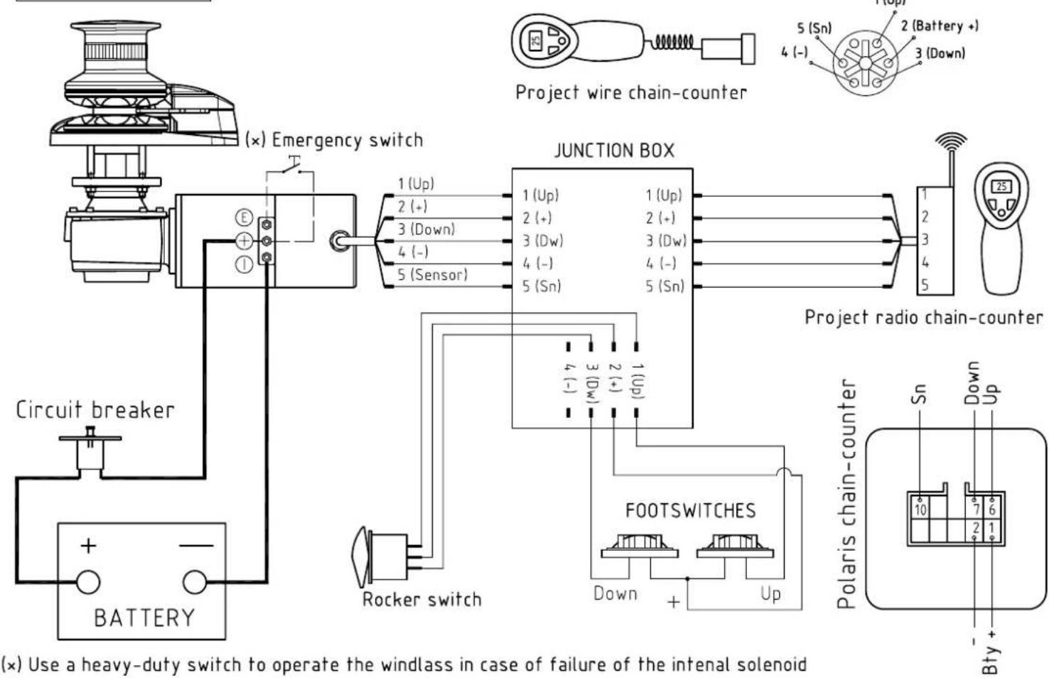
WIRING DIAGRAM WITH JUNCTION BOX
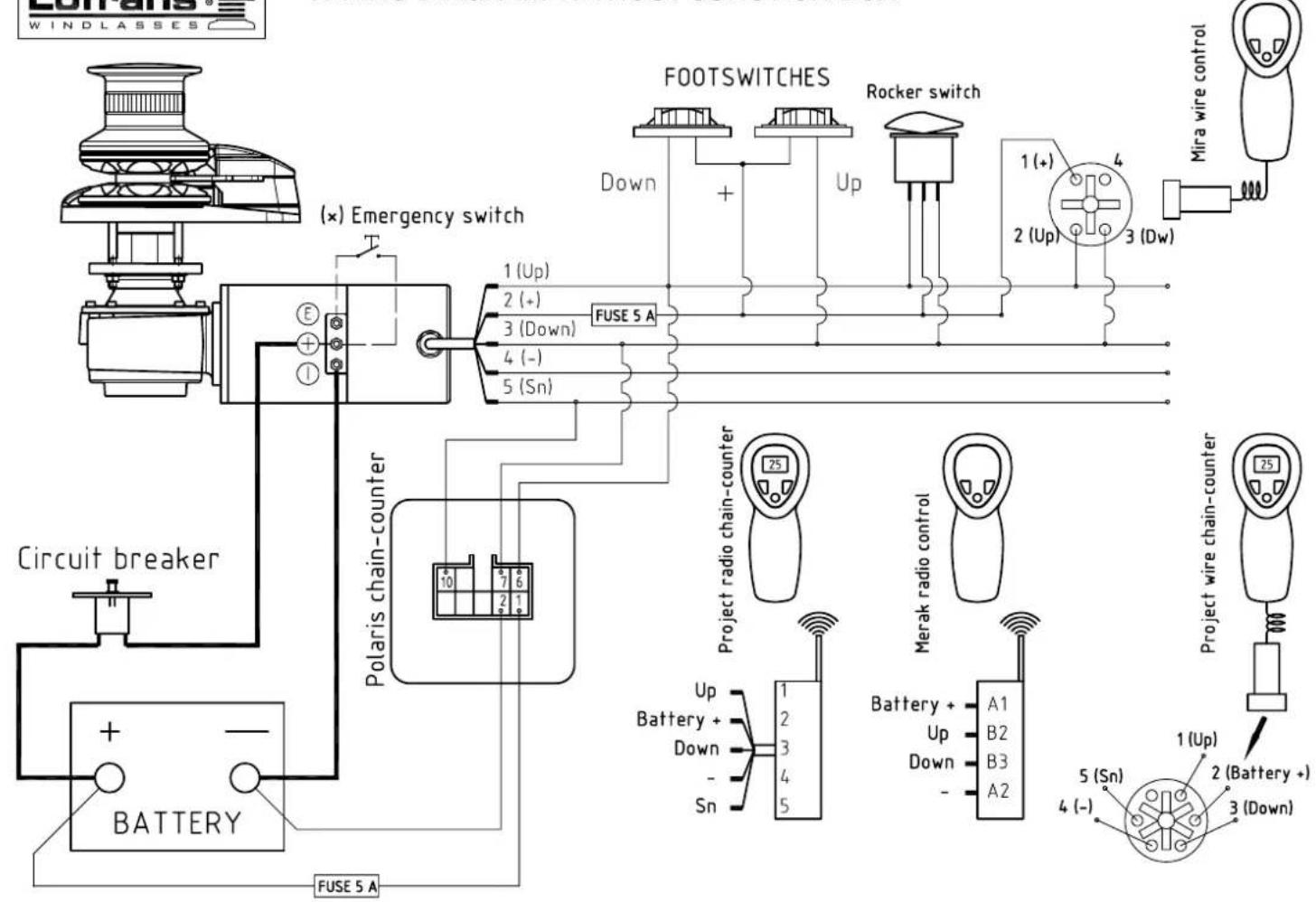
WIRING DIAGRAM WITHOUT JUNCTION BOX

Lofrans
WINDLASSES
PROJECT 1500
code:B.32.101-Rev.A
date: 07-2006
PROJECT 1500
| ItemDescriptionKitQ.tyltemDescriptionKitQ.ty | |||
| 226 Washer for screw M8 Kit B 3 KA32101 Kit A - Seals 1 | |||
| 227 Nut - M8 Kit B 4 KB32101 Kit B - Screw&Nuts 1 | |||
| 260 Spring washer for screw M8 Kit B 3 KC06101 | Kit C - Ke | ||
| 272 | Handle | 1 | |
| 293 | Hd cap screw - M5x16 | Kit F | 1 |
| 309 | Bearing - 6203 | 1 | |
| 311 | Thrust bearing - 51105 | 1 | |
| 312 | Circlip - 43 Din 472 | Kit D 1 | |
| 350 | Round key - 4x6,5 | Kit C 1 | |
| 351 | Hd cap screw - M6x20 | Kit B 6 | |
| 417 | Hex hd screw - M8x30 | Kit B 3 | |
| 450 | Key - 8x7x80 | Kit C 1 | |
| 474 | Oil plug 1/4" | 1 | |
| 524 | Seal - 30x55x10 | Kit A 1 | |
| 526 | Circlip - 30 DIN 471 | Kit D 2 | |
| 534 | Gearcase - upper | 1 | |
| 535 | O Ring - 4500 | Kit A 1 | |
| 536 | Seal - 45x60x7 Kit A 2 | ||
| 537 | Bearing - 16009 | 2 | |
| 538 | Circlip - 100 DIN 472 Kit D 1 | ||
| 539 | Key - 8x7x35 | Kit C 2 | |
| 540 | Sleeve | 1 | |
| 541 | Spring | 1 | |
| 542 | Dog clutch | 1 | |
| 543 | Wormwheel | 1 | |
| 544 | Gearcase - lower | 1 | |
| 545 | Worm | 1 | |
| 546 | Seal - 25x45x10 | Kit A 1 | |
| 619 | Hd cap screw - M6x10 | Kit B 1 | |
| 639 Washer for screw M8 Kit B 4 | |||
| 906 | Spacer | Kit F | 1 |
| 907 | Hd cap screw - M6x50 | Kit B 1 | |
| 909 | Spring | Kit F | 1 |
| 912 | Clutch nut | 1 | |
| 913 | O Ring - 3287 | Kit A 1 | |
| 945 | Cap | Kit F | 1 |
| 980a | Base | 1 | |
| 981 | Support | 1 | |
| 982 | Stripper | 1 | |
| 983a | Cover | 1 | |
| 984 | Hd cap screw - M8x50 | Kit B 2 | |
| 985 | Std main shaft | 1 | |
| 986 | LP main shaft | 1 | |
| 987 | Stainless steel bearing - 6006 2RS | 1 | |
| 988 | Clutch cone | 2 | |
| 989a | Gipsy Ø8 Iso | 1 | |
| 989b | Gipsy Ø10 Iso - Ø3/8" G40 | 1 | |
| 989c | Gipsy Ø10 Din766 | 1 | |
| 989d | Gipsy Ø12 Iso-Ø13 Din766 | 1 | |
| 990 | Spacer | 1 | |
| 991a | Drum | 1 | |
| 992 | Gasket | 1 | |
| 993a Gipsy cap | 1 | ||
| 997 | Circlip - 55 DIN 472 | Kit D 1 | |
| 998a | Finger Kit F 1 | ||
| 998b Stainless steel finger (option) Kit F 1 | |||
| 1008 | Pivot 8x14 | Kit F | 1 |
| 1009a | Electric motor 1500W 12V | 1 | |
| 1009b | Electric motor 1500W 24V | 1 | |
| 1026 | Plastic cap for sensor | 1 | |
| 1033 | Stud - M8x105 | 4 | |
| 1 | |||
| KD06101 | Kit D - Circlips | 1 | |
| KF32101 | Kit F - Finger | 1 | |
| KF32102 | Kit F - S/S Finger (option) | 1 | |
| 1 | |||
LOFRANS' SALES ORGANIZATION
| ARGENTINA DOMINO P. PEDRONI S.A.C. 9 de Julio 198 - 1646 S. Fernando - Bs..As. | EGYPT MAPSO Marine Propulsion and Supply S.A.E. 11(A) Mohamed Anis St. Zamalek - Cairo | GREECE ALEX MARINE 5 Leochrous Str. 185 31 Piraeus | POLAND MAZURIA 11 214 Galiny 2 |
| AUSTRIA G.ASCHERL GmbH Erlengrund 38 - 6971 Hard HARTMANN Hafenstrasse 5 A - 6971 Hard a. Bodensee | ENGLAND E.C. SMITH & SONS LTD. Unit H & J Kingsway - Industrial Estate, Kingsway Luton Beds , LU1 1LP | HONG KONG ELCO MARINE & ENGINEERING LTD. 20 Yip Fung Street Unit 6 , G/F - Lincoln Centre - Fanling New Territories HONG KONG | PORTUGAL NAUTICOR Rua Bartolomeu Dias 172 A/D 1400 Lisboa |
| BAHRAIN - ARABIAN GULF 2000 MARINE STORES P.O. Box 26927 Manama | FINLAND OY MARITIM AB P.O. Box 46 00211 Helsinki 21 | ISRAEL ATLANTIS MARINE LTD 147 Kikar Atarim 169 Hayarkon Str. - Tel Aviv 63453 | SINGAPORE AMERICAN MARINE (S) PTE LTD. No. 26 Jalan Terusan Jurong Town Singapore 2261 |
| BELGIUM HUNTER N.V. St. Bernardsesteenveg 858-864 2660 Hoboken (Antwerpen) | FRANCE ACCASTILLAGE BERNARD 880 Avenue Saint Exupéry 06210 Mandelieu | LEBANON MARINE DIFFUSION B.P. 8389 Beyouth | SOUTH AFRICA MANEX & POWER MARINE (PTY) LTD. 19 Dorsetshire Street - P.O. Box 182 7420 Paarden Eiland-Cape Town |
| CANADA REKORD MARINE ENTERPRISES Ltd. 8194 Ontario Street Vancouver B.C. V5X 3E3 | AMIOT S.A. 41, Quai Duguay-Trouin - Boîte Postale 106 35407 Saint-Malo | MALTA INTERNATIONAL MARINE CENTRE Ta'Xbiex Palace Testaferrata Street Msida | SPAIN LA INDUSTRIAL VELERA MARSAL S.A. Muntadas 8 y 10 08014 Barcelona IMNASA S.A. Adva. Zaragoza 73/75 17220 Sant Feliu de Guixols (Girona) |
| CANARY ISLANDS NORDEST - Roberto Origi Ap. de Correo 10431 38080 Santa Cruz de Tenerife | ELECTRIC-AUTO-YACHTING S.A.R.L. 6, Rue de la Paix 13001 Marseille | NEW CALEDONIE LIMOUSIN MARINE 70, R.Ie du Port Despointes-B. P. 701 Noumea | SWEDEN ITALNORDIC Forretagsvagen - Box 12 440 90 Henan |
| CARIBBEAN BUDGET MARINE N.V. P.O. Box 434 25B Waterfront Road - Cole Bay - St. Maarten | R.E.Y.A. 144, Avenue de la Roubine 06150 Cannes-La Boca | NEW ZELAND EUROMARINE P.O. BOX 10144 Dominion Road-Aukland 10 | TAIWAN GENCO MARINE LTD. Suite 5F 5 169 Min Shen East Road, Sec.5 P.O. Box 87-908 - Taipei Taiwan 10582 |
| CROATIA -SLOVENJA UNIMAR S.r.l. Via Valdirivio 26 34134 Trieste-Italy | SEMI S.A. Rue Alain-Colas ZIP-Port du Moulin Blanc - Boîte Postale 243 29272 Brest | NEDERLANDS VETUS DEN OUDEN N.V. Fokkerstrat 571 3125 Bd Schiedam | TURKEY CARKCI DENIZCILIK San.Vc.Tic.Ltd. Sti. Ozek skt tersalener yolu nuh sanayi siti si 36 Icmeler Tusla - Istambul |
| CYPRUS MERCURY DIVERS COMPANY LTD. 15. Franlin Roosvelt Av. - Orphanides House P.O. Box 469 - Limassol | VIDAL DIFFUSION MARINE Z.I. Toulon EST Toulon Cedex 9 | HUNGARY MIMOKER Co. Orso' Utca 3 H 1026 Budapest | U.S.A. IMTRA CORPORATION 30 Samuel Barnet Blvd - New Bedford Industrial Park New Bedford Massachusetts 02745 |
| DENMARK PALBY MARINE A/S Bommerhavvej 41 Sledde DK 7100 Vejle | GERMANY S.V.B. Gelsenkirchner st. 25 28199 Bremen | NORWAY TELMO CONTROL A.S. Rolf Hofmos GT. 18 - Postboks 2906 Toyen 0608 OSLO 6 |
LOFRANS IS NOT IN ANY WAY BE RESPONSIBLE FOR SELECTION OF A WINDCLASS BY OTHERS.
Brand : Lofrans
Model : Project 1500
Category : Winch