
10267407 - Smart Home RWE - Free user manual and instructions
Find the device manual for free 10267407 RWE in PDF.
| Product type | Smart home flush-mounted switch |
| Brand | RWE |
| Model | 10267407 |
| Power supply | 230 V / 50 Hz |
| Standby consumption | 1 W |
| Radio frequency | 868.3 MHz |
| Max transmission power | 10 mW |
| Max switching power | 1000 W (resistive load) |
| Minimum load | 10 W |
| Minimum current | 40 mA |
| Relay | Changeover contact, 5 A resistive load |
| Protection rating | IP20 |
| Protection class | II |
| Ambient temperature | +5 °C to +35 °C |
| Dimensions (W x H x D) | 71 x 71 x 37 mm |
| Weight | 43 g |
| Main functions | Switching on/off of lamps and variable luminaires; control via wall transmitter, remote control, SmartHome software or central unit; manual switching possible |
| Switching type | Simple, two-way, cross |
| Installation | Reserved for a certified electrician; compliance with DIN 49073-1 and the 5 safety rules |
| Maintenance and cleaning | No maintenance; do not open; clean with a dry cloth if necessary |
| Safety | Disconnect the circuit breaker before installation; do not exceed the rated power; indoor use only |
| Spare parts and repairability | No user-replaceable parts; contact customer service in case of defect |
| General information | Compliant with directive 1999/5/EC; disposal according to WEEE |
Frequently Asked Questions - 10267407 RWE
User questions about 10267407 RWE
0 question about this device. Answer the ones you know or ask your own.
Ask a new question about this device
Download the instructions for your Smart Home in PDF format for free! Find your manual 10267407 - RWE and take your electronic device back in hand. On this page are published all the documents necessary for the use of your device. 10267407 by RWE.
USER MANUAL 10267407 RWE
The inwall light switch enables lamps and luminaires connected to it to be switched on and off. The switching operations are user-controlled, based on remote commands received.
Remote commands are issued either by the SmartHome software or program-controlled via the central unit.
The rocker function can be configured in the SmartHome software so that it can also activate other devices.

Hazard warning
- Do not open the inwall light switch. It does not contain any parts to be serviced by the user. If a fault occurs, please contact our Customer Service.
- Only operate the device indoors. Avoid the influence of humidity, dust, sunlight and other heat radiation.
- Do not push the inwall light switch beyond the specified performance limit.
-
The inwall light switch is part of the building installation. The standards and guidelines applicable in the country of installation must be complied with during planning and installation. This device must only be operated on the 230 V / 50 Hz AC mains. Work on the 230 V mains must be performed only by an electrical engineer certified in your country. The applicable occupational health and safety rules must also be followed here. To prevent the risk of electric shock, disconnect the mains supply to the device (switch off the circuit breaker). Failure to comply with the installation instructions may result in a fire or cause other hazards.
-
When establishing the connections to the device terminals, make sure that you use the approved cables and cable cross-sections:
| Rigid cable Flexible cable without wire end sleeve |
1.00-1.50mm²
1.00-1.50mm
- Before connecting a device, refer to the technical data - in particular the maximum permitted connected load of the light switch and the types of device that can be connected. All stated loads are ohmic loads.
- Overloading can destroy the device or cause a fire or an electrical accident.
- The fuse in the fuse box must be removed before the inwall light switch can be connected.
- Installation is only permitted in standard outlet sockets (device sockets) in accordance with DIN 49073-1.
- The device must only be operated with the corresponding switch cover correctly mounted in place
Mandatory information in accordance with the equipment safety standard
Note! Only to be installed by persons with relevant electrical qualifications and experience. (*1)
Improper installation will result in
- Risk to your own life;
- Risk to the life of persons using the electrical equipment.
Severe material damage (e.g. due to fire) may result if the equipment is not installed correctly. You may be personally liable in the event of personal injury or material damage.
Please contact a qualified electrical engineer!
(^*1) Specialist knowledge required for installation
The following specialist information in particular is required for the installation:
The applicable "5 Safety Rules": disconnection; securing the system so that it cannot be switched back on again; verifying that the system is de-energised; earthing and short-circuiting; covering adjacent current-carrying components or making them inaccessible;
Selection of suitable tools, measuring equipment and - if necessary - personal protection equipment;
- Evaluation of measurement results;
Selection of the electrical installation material to ensure compliance with the shut-down conditions;
IP protection classes;
- Installation of the electrical installation material;
- Identification of the supply grid type (TN system, IT system, TT system) and the resulting connection conditions (conventional protective multiple earthing, safety earthing, additional measures required etc.).
Commissioning
Three circuit configurations are possible depending on the pre-installed wiring.
1 Switch off the house circuit breaker in the circuit.
2 Remove all plastic components and the existing switch, if any.
3 Make a note of the serial number located underneath the barcode.
The fourth step depends on the desired circuit configuration.
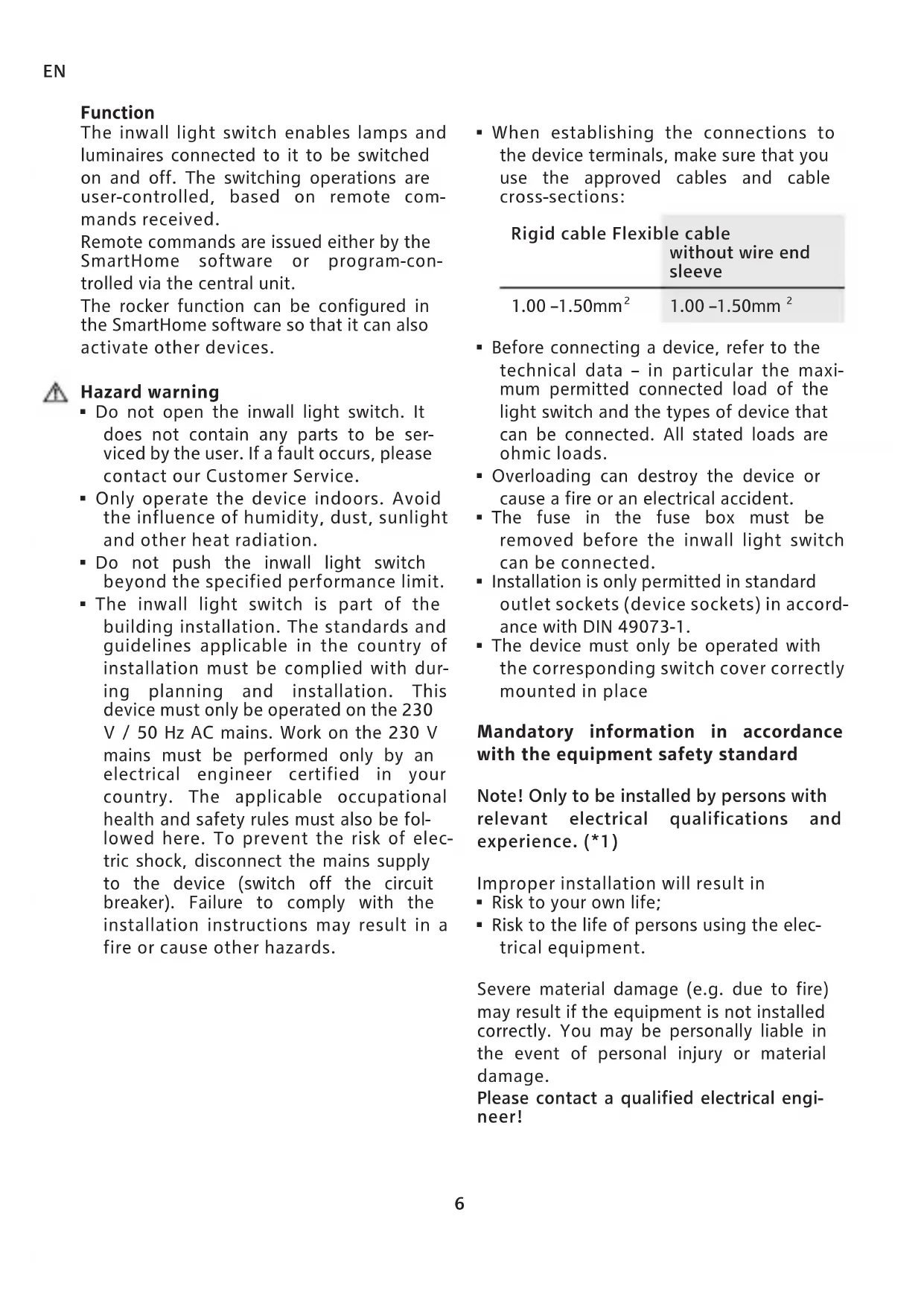
On-off circuit
4 Connect the conductor for the lamp/ light (D) to terminal 2.
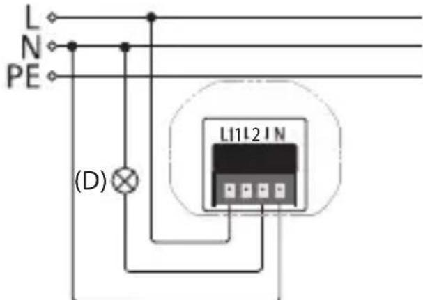
Two-way circuit
4 Connect the two corresponding leads for two-way switch E to terminals 1 and 2.
- The inwall light switch may only be installed in exchange for the two-way switch if it is connected to external conductor L of the relevant two-way circuit.
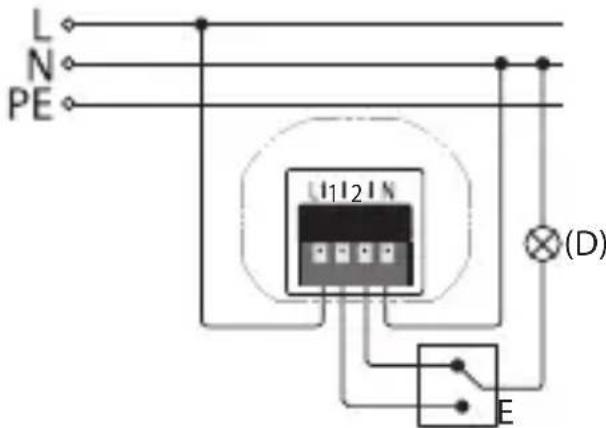
Intermediate switch circuit
4 Connect the two corresponding leads for intermediate switch circuit F to terminals 1 and 2.
- When you install the inwall light switch in an intermediate switch circuit, it may only be used in exchange for the two-way switch if it is connected to external conductor L.
The following steps apply to all circuit configurations.
5 Connect the external conductor to terminal L.
6 Connect the neutral conductor to terminal N.
7 Attach the inwall light switch to the inwall box using the enclosed screws.
8 Hold the frame on the inwall light switch and attach the latter by pushing on the appropriate rocker adapter.
9 Switch the house circuit breaker in the circuit back on.
10 Integrate the device via the user software in the SmartHome system.
11 Fit the rocker.
General information
eQ-3 Entwicklung GmbH hereby declares that this device meets the basic requirements and the other relevant regulations laid down in Directive 1999/5/EC.
You can find the complete declaration of conformity at:
www.eq-3.de/service/downloads.html
| Name of device ISS2 | |
| Supply voltage 230V/50Hz | |
| Standby consump- tion | 1W |
| Radio frequency 868.3MHz | |
| Max. transmission power | 10mW |
| Receiver class SRD category 2 | |
| Max. switching power | 1000W |
| Minimum load 10W | |
| Minimum current 40mA | |
| Relay Changeover contact | |
| Switching capacity 5A (ohmic load) | |
| Protection class IP20 | |
| Protection cate- gory | II |
| Ambient tempera- ture | +5°C to +35°C |
| Dimensions 71x71x37mm (WxHxD) | |
| Weight 43g | |
Technical changes reserved.
Information about disposal

Do not dispose of the device in the household waste! Electronic devices are to be disposed of via the local collection points for old electronic devices in accordance with the Waste Electrical and Electronic Equipment Directive.
5th English edition 09/2016
Documentation © innogy SE, Germany. All rights reserved. We accept no liability for errors of a technical or typographical nature or their consequences. All trademarks and property rights are recognised.
Changes in response to technical progress can be made without prior notice.
innogy SE
Flamingoweg 1
44139 Dortmund
Germany