CCT9851N - Basket CANDY - Free user manual and instructions
Find the device manual for free CCT9851N CANDY in PDF.
Frequently Asked Questions - CCT9851N CANDY
User questions about CCT9851N CANDY
0 question about this device. Answer the ones you know or ask your own.
Ask a new question about this device
Download the instructions for your Basket in PDF format for free! Find your manual CCT9851N - CANDY and take your electronic device back in hand. On this page are published all the documents necessary for the use of your device. CCT9851N by CANDY.
USER MANUAL CCT9851N CANDY
text_image
Diagram illustrating a mechanical assembly or inspection procedure with labeled components A and B, showing tool application and directional arrows.Fig.2 Fig.3
text_image
Technical diagram showing a mechanical assembly with labeled components A and C, including a spring-loaded component and directional arrows.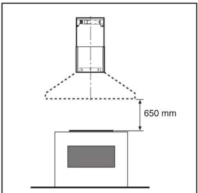
text_image
650 mmFig.4 Fig.5
text_image
Diagram illustrating hand tool application on a cutting board, with numbered arrows indicating motion and adjustment steps.Fig.6
natural_image
Diagram of a mechanical device with a 90-degree angle indicator and directional arrow (no text or symbols on the diagram itself)Fig.7
flowchart
graph TD
    A["Sun icon"] --> B["A"]
    C["0"] --> D["B"]
    E["1"] --> F["C"]
    G["2"] --> H["D"]
    I["3"] --> J["E"]
    K["T"] --> L["F"]
Fig.8
flowchart
graph TD
    A["A"] -->|A1| B["A1"]
    A -->|A2| C["A2"]
    D["Device 1"] --> E["Light Source"]
    F["Device 2"] --> G["Light Source"]
    H["Device 3"] --> I["Light Source"]
    J["Device 4"] --> K["Light Source"]
    L["C"] --> M["C"]
    N["C1"] --> O["C1"]
    P["C2"] --> Q["C2"]
    R["C3"] --> S["C3"]
    T["C4"] --> U["C4"]
flowchart
graph TD
    A["○"] --> G["G"]
    B["○"] --> B["B"]
    C["1"] --> C["C"]
    D["2"] --> D["D"]
    E["3"] --> E["E"]
    F["▽"] --> A["A"]
Fig.9 Fig.10
text_image
Diagram illustrating a laboratory procedure with labeled components A, B, and C, showing a pipette and test tube setup.Fig.11 Fig.12
text_image
INCANDESCENT TUBOLAR LAMP Ø 25mm - L85- E14 - 40W CANDLE HALOGEN LAMP Ø 35mm - E14 - 28WGENERALITÀ
INSTALLATIE INSTRUCTIES
C = Knop EERSTE SNELHEID
D=Knop TWEEDW DERDE SNELHEID
E = Knop DERDE SNELHEID
F = Knop TIMER AUTOMATISCHE ONDERBREKING na 15 minuten (*)
C = Knop EERSTE SNELHEID
D= Knop TWEEDW DERDE SNELHEID
E=Knop DERDE SNELHEID
G = Controlelampje WERKENDE MOTOR.
C3 = Toets TWEEDE SNELHEID
C4= Toets DERDE SNELHEID.
$$ \mathbf {C 2} = \text { T e c l a P R I M E I R A V E L O C I D A D E } $$
$$ \mathbf {C 3} = \text { T e c l a S E G U N D A V E L O C I D A D E } $$
C4 = Tecla TERCEIRA VELOCIDADE.
Carefully read the following important information regarding installation safety and maintenance. Keep this information booklet accessible for further consultations. The appliance has been designed for use in the ducting version (air exhaust to the outside - Fig.1B), filtering version (air circulation on the inside - Fig.1A).
SAFETY PRECAUTION
- Take care when the cooker hood is operating simultaneously with an open fireplace or burner that depend on the air in the environment and are supplied by other than electrical energy, as the cooker hood removes the air from the environment which a burner or fireplace need for combustion. The negative pressure in the environment must not exceed 4Pa (4x10⁻⁵ bar). Provide adequate ventilation in the environment for a safe operation of the cooker hood. Follow the local laws applicable for external air evacuation.
Before connecting the model to the electricity network:
- Control the data plate (positioned inside the appliance) to ascertain that the voltage and power correspond to the network and the socket is suitable. If in doubt ask a qualified electrician.
- If the power supply cable is damaged, it must be replaced with another cable or a special assembly, which may be obtained direct from the manufacturer or from the Technical Assistance Centre.
- This device must be connected to the supply network through either a plug fused 3A or hardwired to a 2 fase spur protected by 3A fuse.
2. Warning!
In certain circumstances electrical appliances may be a danger hazard.
A) Do not check the status of the filters while the cooker hood is operating.
B) Do not touch bulbs or adjacent areas, during or straight after prolonged use of the lighting installation.
C) Flambè cooking is prohibited underneath the cooker hood.
D) Avoid free flame, as it is damaging for the filters and a fire hazard.
E) Constantly check food frying to avoid that the overheated oil may become a fire hazard.
F) Disconnect the electrical plug prior to any maintenance.
G) This appliance is not intended for use by young children or infirm persons without supervision.
H) Young children should be supervised to ensure they do not play with the appliance.
I) There shall be adequate ventilation of the room when the rangehood is used at the same time as appliances burning gas or other fuels.
L) There is a risk of fire if cleaning is not carried out in accordance with the instructions.
This appliance conforms to the European Directive EC/2002/96, Waste Electrical and Electronic Equipment (WEEE). By making sure that this appliance is disposed of in a suitable manner, the user is helping to prevent potential damage to the environment or to public health.
The symbol on the product or on the accompanying paperwork indicates that the appliance should not be treated as domestic waste, but should be delivered to a suitable electric and electronic appliance recycling collection point. Follow local guidelines when disposing of waste. For more information on the treatment, re-use and recycling of this product, please contact your local authority, domestic waste collection service or the shop where the appliance was purchased.
INSTALLATION INSTRUCTIONS
- Assembly and electrical connections must be carried out by specialised personnel.
- Wear protective gloves before proceeding with the installation.
• Electric Connection:
- The appliance has been manufactured as a class II, therefore no earth cable is necessary. The plug must be easily accessible after the installation of the appliance. If the appliance is equipped with power cord without plug, a suitably dimensioned omnipolar switch with 3 mm minimum opening between contacts must be fitted between the appliance and the electricity supply in compliance with the load and current regulations.
- The connection to the mains is carried out as follows: BROWN = L line
BLUE = N neutral.
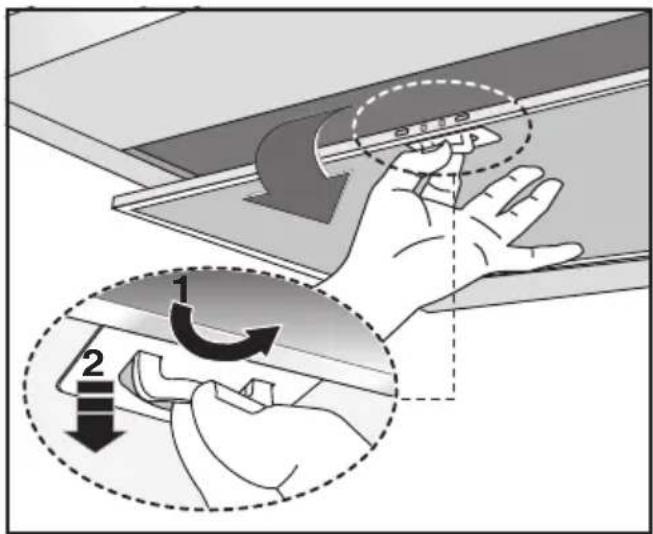
- If the hob is electric, gas, or induction, the minimum distance between the same and the lower part of the hood must be at least 65 cm (Fig.5). If a connection tube composed of two parts is used, the upper part must be placed outside the lower part. Do not connect the cooker hood exhaust to the same conductor used to circulate hot air or for evacuating fumes from other appliances generated by other than an electrical source. Before proceeding with the assembly operations, remove the anti-grease filter(s) (Fig.6) so that the unit is easier to handle.
- In the case of assembly of the appliance in the suction version prepare the hole for evacuation of the air.
- We recommend the use of an air exhaust tube which has the same diameter as the air exhaust outlet hole. If a pipe with a smaller diameter is used, the efficiency of the product may be reduced and its operation may become noisier.
- Fixing to the wall:
Drill the holes A respecting the distances indicated (Fig.2). Fix the appliance to the wall and align it in horizontal position to the wall units. When the appliance has been adjusted, definitely fix the hood using the screws A (Fig.4). For the various installations use screws and screw anchors suited to the type of wall (e.g. reinforced concrete, plasterboard, etc.). If the screws and screw anchors are provided with the product, check that they are suitable for the type of wall on which the hood is to be fixed.
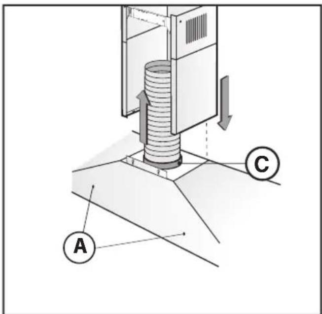
• Fixing the decorative telescopic flue:
Arrange the electrical power supply within the dimensions of the decorative flue. If your appliance is to be installed in the ducting version or in the version with external motor, prepare the air exhaust opening. Adjust the width of the support
bracket of the upper flue (Fig.3). Then fix it to the ceiling using the screws A (Fig.3) in such a way that it is in line with your hood and respecting the distance from the ceiling indicated in Fig.2. Connect the flange C to the air exhaust hole using a connection pipe (Fig.4). Insert the upper flue into the lower flue and rest above the frame. Extract the upper flue up to the bracket and fix it with the screws B (Fig.3). To transform the hood from a ducting version into a filtering version, ask your dealer for the charcoal filters and follow the installation instructions.
- Filtering version:
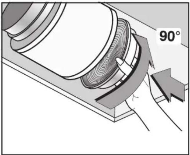
Install the hood and the two flues as described in the paragraph for installation of the hood in ducting version. To assemble the filtering flue refer to the instructions contained in the kit. If the kit is not provided, order it from your dealer as accessory. The filters must be applied to the suction unit positioned inside the hood. They must be centred by turning them 90 degrees until the stop catch is tripped (Fig.7).
USE AND MAINTENANCE
- We recommend that the cooker hood is switched on before any food is cooked. We also recommend that the appliance is left running for 15 minutes after the food is cooked, in order to thoroughly eliminate all contaminated air. The effective performance of the cooker hood depends on constant maintenance; the anti-grease filter and the active carbon filter both require special attention.
- The anti-grease filter is responsible retaining the grease particles suspended in the air, therefore it is subject to clogging with variable frequency according to the use of the appliance.
- To prevent the danger of possible fires, at least every 2 months one must wash the anti-grease filters by hand using non-abrasive neutral liquid detergents or in the dishwasher at low temperatures and on short cycles.
- In the event that acrylic anti-grease filters are used, handwash every 2 months, using neutral non-abrasive liquid detergents and replace them after every 6 washes.
- After a few washes, colour alterations may occur. This does not give the right to claim their replacement.
- The active carbon filters are used to purify the air that is sent back into the room and its function is to mitigate the unpleasant odours produced by cooking.
- The non-regenerable active carbon filters must be replaced at least every 4 months. The saturation of the active charcoal depends on the more or less prolonged use of the appliance, on the type of kitchen and on the frequency with which anti-grease filter is cleaned.
- Before remounting the anti-grease filters and the regenerable active charcoal filters it is important that they are completely dry.
- Clean the hood frequently, both internally and externally, using a cloth dampened with denatured alcohol or neutral liquid detergents that are non abrasive.
- The lighting .system is designed for use during cooking and not for the prolonged general lighting of the room. The prolonged use of the lighting system significantly decreases the average duration of the bulbs.
- Attention: the non compliance with the hood cleaning warnings and with the replacement and cleaning of the filters entails risk of fires. One therefore recommends keeping to the suggested instructions.
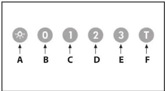
- Commands luminous (Fig.8) the key symbols are explained below:
$$ \mathbf {A} = \text { LIGHT } $$
$$ \mathbf {B} = \text { O F F } $$
$$ \mathbf {C} = \text { SPEED } \mathbf {I} $$
$$ \mathbf {D} = \text { SPEED II } $$
$$ E = S P E E D \text { III } $$
$$ \mathbf {F} = \text { AUTOMATIC STOP TIMER } - 1 5 \text { minutes } (*) $$
If your appliance has the INTENSIVE speed function, from speed THREE, press key E for 2 seconds and it will be activated for 10 minutes after which it will return to the previously set speed. When the function is active the LED flashes. To interrupt it before the 10 minutes have elapsed, press key E again. Some models allow activating this function even with speed one and two.
By pressing key F for two seconds (with the hood switched off) the "clean air" function is activated. This function switches the appliance on for ten minutes every hour at the first speed. As soon as this function is activated the motor starts up at the first speed for ten minutes. During this time key F and key C must flash at the same time. After ten minutes the motor switches off and the LED of key F remains switched on with a fixed light until the motor starts up again at the first speed after fifty minutes and keys F and C start to flash again for ten minutes and so on. By pressing any key for the exclusion of the hood light the hood will return immediately to its normal functioning (e.g. if key D is pressed the "clean air" function is deactivated and the motor moves to the 2nd speed straight away. By pressing key B the function is deactivated).
(*) The "AUTOMATIC STOP TIMER" delays stopping of the hood, which will continue functioning for 15 minutes at the operating speed set at the time this function is activated.
• Anti-grease/active charcoal filters saturation:
-When the A key flashes with a 2 second frequency the anti-grease filters must be washed.
-When the A key flashes with a 0.5 second frequency the active carbon filters must be replaced or washed depending on the type of filter.
Once the clean filter has been put back one must reset the electronic memory by pressing the A key for approximately 5 seconds until it stops flashing.
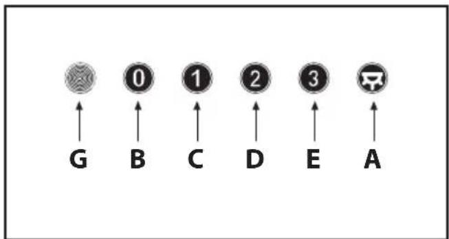
- Commands mechanical (Fig.9) the key symbols are explained below:
$$ \mathbf {A} = \text { LIGHT } $$
$$ \mathbf {B} = \text { O F F } $$
$$ \mathbf {C} = \text { SPEEDI } $$
$$ \mathbf {D} = \text { SPEED II } $$
$$ \mathbf {E} = \text { SPEED III } $$
$$ \mathbf {G} = \text { MOTOR WORKING indicator. } $$
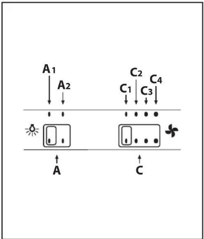
- Commands slider (Fig.10) the key symbols are explained below:
$$ \mathbf {A} = \text { Light switch } $$
$$ \mathbf {A 1} = \text { Off key } $$
$$ \mathbf {A 2} = \text { On key } $$
$$ \mathbf {C} = \text { Speed control } $$
$$ \mathbf {C 1} = \text { Off key } $$
$$ \mathbf {C 2} = \text { FIRST SPEED key } $$
$$ \mathbf {C 3} = \text { SECOND SPEED key } $$
$$ \mathbf {C 4} = \text { THIRD SPEED key. } $$
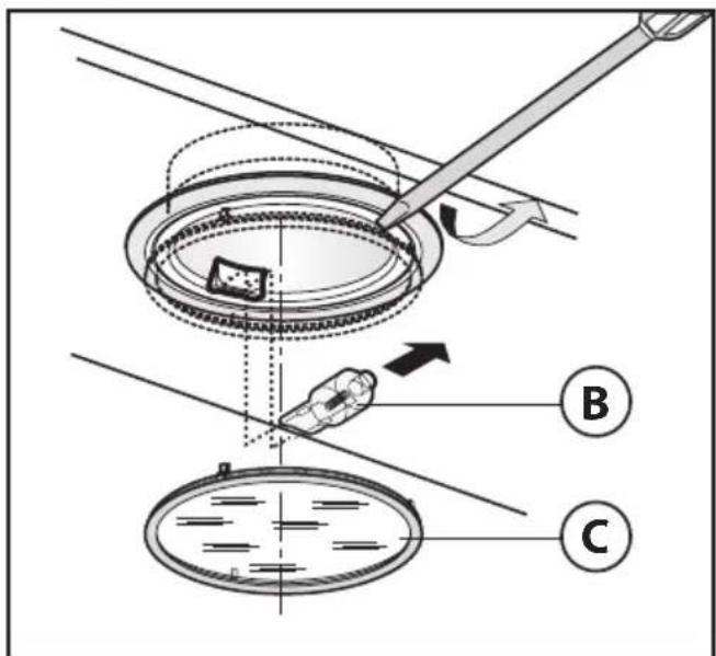
- Replacing halogen light bulbs (Fig.11):
To replace the halogen light bulbs B, remove the glass pane C using a lever action on the relevant cracks.
Replace the bulbs with new ones of the same type.
Caution: do not touch the light bulb with bare hands.
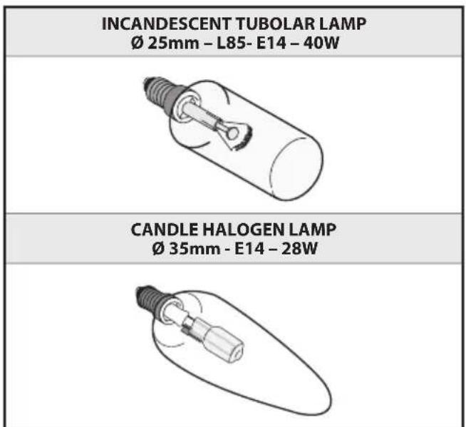
- Replacing the halogen/incandescent lamps (Fig.12):
Only use lamps of the same type and Wattage installed on the device.
CUSTOMER ASSISTANCE SERVICE
Before contacting the Technical Assistance Service:
If the product does not operate at all, we advise you to:
- check that the plug has been inserted into the power socket correctly.
If you cannot identify the cause of the operating anomaly: switch off the appliance (do not subject it to rough treatment) and contact the Assistance Service.
PRODUCT SERIAL NUMBER. Where can I find it?
It is important that you inform the Assistance Service of your product code and its serial number (a 16-character code which begins with the number 3); this can be found on the guarantee certificate or on the data plate located inside the appliance.
This will help to avoid wasted journeys being made by technicians, thereby (and most significantly) saving the corresponding callout charges.
THE MANUFACTURER DECLINES ALL RESPONSIBILITY FOR EVENTUAL DAMAGES CAUSED BY BREACHING THE ABOVE WARNINGS.
ÚVOD'
D = Toisen nopeuden painike
E = Kolmannen nopeuden painike
G = ενδειξη KINHTHPA ΣΕ ΛΕΙΤΟΥΡΓΕΙΑ.
A = Tast for BELYSNING
B = Tast for OFF (AV)
C = Tast for F∅RSTE HASTIGHET
D = Tast for ANNEN HASTIGHET
E = Tast for TREDJE HASTIGHET
F = Tast TIDSURE AUTOMATISK STOPP 15 minutter (*)
A = Tast for BELYSNING
B = Tast for OFF (AV)
C = Tast for F∅RSTE HASTIGHET
D = Tast for ANNEN HASTIGHET
E = Tast for TREDJE HASTIGHET
G = Kontrollampe for MOTOR I FUNKSJON.
•Kommandoer slider (Fig.10) symbolenes betydning:
A = Lysbryter
A1 = Tast Off
A2 = Tast On
C = Hastighetskontroll
C1 = Tast Off
C2 = Tast HASTIGHET EN
C3 = Tast HASTIGHET TO
C4 = Tast HASTIGHET TRE.
G = Semnal luminos MOTOR ÎN FUNCTIUNE.
C = Knapp FÖRSTA HASTIGHET
D= Knapp ANDRA HASTIGHET
E = Knapp TREDJE HASTIGHET
F = TIMER FÖR AUTOMATISK AVSTÄNGNING EFTER 15 minuter (*)
C = Knapp FÖRSTA HASTIGHET
D= Knapp ANDRA HASTIGHET
E = Knapp TREDJE HASTIGHET
G = Kontrollampa MOTORN I FUNKTION.
• Kommandoknappar slider (Fig.10):
A = Knapp till belysningen
A1 = Avstängningsknapp
A2 = Startknapp
C2 = Gumb PRVA HITROST
C3 = Gumb DRUGA HITROST
C4 = Gumb TRETJA HITROST.