
GCPT 25381 I AS - Brush cutter EINHELL - Free user manual and instructions
Find the device manual for free GCPT 25381 I AS EINHELL in PDF.

| Product Type | Petrol Brushcutter |
| Brand | Einhell |
| Model | GCPT 25381 I AS |
| Engine | 2-stroke, air-cooled, chrome cylinder |
| Maximum Power | 0.6 kW (0.8 HP) |
| Displacement | 25.4 cm³ |
| Engine Idle Speed | 3000 ± 400 rpm |
| Maximum Engine Speed | 8500 rpm |
| Ignition | Electronic |
| Drive | Centrifugal Clutch |
| Weight (empty tank) | 5.6 kg |
| Cutting Circle Diameter | 38 cm |
| Cutting Line Length | 4.0 m |
| Cutting Line Diameter | 2.0 mm |
| Tank Capacity | 0.45 L |
| Fuel | Unleaded petrol and 2-stroke oil mixture (40:1) |
| Sound Pressure Level (LpA) | 89.8 dB(A) |
| Sound Power Level (LWA) | 112 dB(A) |
| Vibration Emission Value | 7.2 m/s² (uncertainty K=1.5 m/s²) |
| Spark Plug | L8RTC / BPM6A |
| Protection Cover | With integrated blade for automatic line cutting |
| Shoulder Strap | Included, adjustable |
| Warranty | 24 months |
| Air Filter Maintenance | Every 25 service hours |
| Spark Plug Maintenance | First check at 10 h, then every 50 h |
Frequently Asked Questions - GCPT 25381 I AS EINHELL
User questions about GCPT 25381 I AS EINHELL
0 question about this device. Answer the ones you know or ask your own.
Ask a new question about this device
Download the instructions for your Brush cutter in PDF format for free! Find your manual GCPT 25381 I AS - EINHELL and take your electronic device back in hand. On this page are published all the documents necessary for the use of your device. GCPT 25381 I AS by EINHELL.
USER MANUAL GCPT 25381 I AS EINHELL
Read and follow the operating instructions and safety information before using for the first time.
natural_image
Close-up of a black plastic hose with a small inset showing two numbered items (17 and 3), no text or symbols present.
natural_image
Close-up of a black mechanical rope or cable being adjusted, with a numbered label pointing to the rope (no text or symbols on the object itself)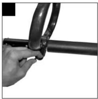
natural_image
Close-up of a hand holding a black metal pipe fitting with rings (no text or symbols visible)
natural_image
Close-up of a hand holding a mechanical component with labeled parts (5a and 14), no readable text or symbols beyond labels.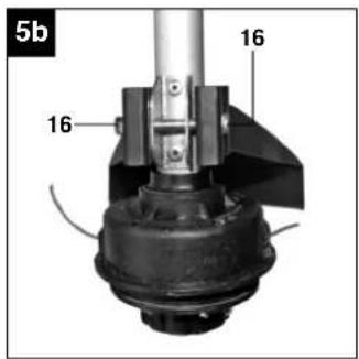
natural_image
Close-up of a hand holding a mechanical component with an arrow indicating motion (no text or symbols visible)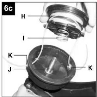
natural_image
Technical line drawing of a mechanical component with gears and housing (no text or symbols)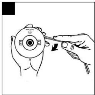
natural_image
Illustration of hands using a tool to adjust a circular component (no text or symbols visible)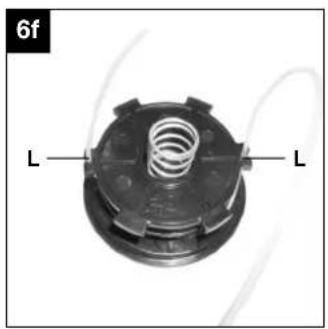
natural_image
Close-up of a mechanical component with two labeled parts (L), no readable text or symbols present.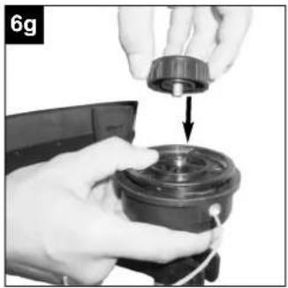
natural_image
Close-up of hands assembling a mechanical component with a downward arrow indicating assembly (no text or symbols visible)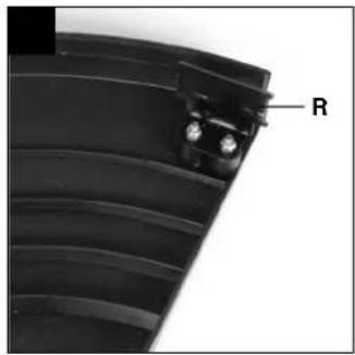
natural_image
Black cylindrical object with attached metal chain and label '15' (no text or symbols on body)
natural_image
Illustration of two workers spraying water with equipment, no text or symbols present
natural_image
Simple line drawing of a mechanical device with a downward arrow indicating motion (no text or symbols)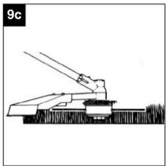
natural_image
Diagram of a mechanical device with lever and base, no visible text or symbols
natural_image
Illustration of a manual lawn saw cutting through grass with motion arrows indicating direction (no text or symbols)
natural_image
Diagram of a mechanical device with rotating blades and a lever, resting on a textured surface (no text or symbols)
natural_image
Close-up of a hand operating a mechanical device with labeled parts (8), no readable text or symbols beyond labels
natural_image
Close-up of a mechanical device with labeled parts (10c and 22), no readable text or symbols beyond labels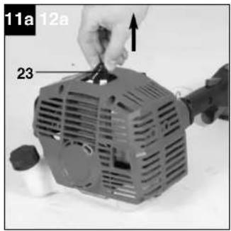

natural_image
Close-up of a mechanical device with internal components and a labeled part '11b' (no readable text or symbols)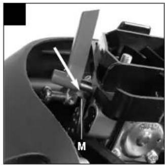
natural_image
Close-up of a mechanical device with labeled component 'M' (no readable text or symbols beyond label)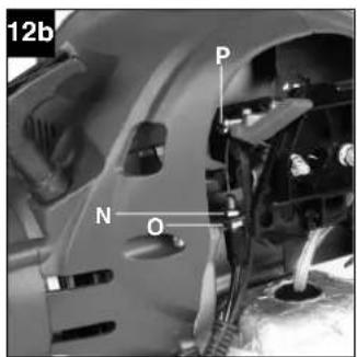
- Safety information
- Layout
- Items supplied
- Intended use
- Technical data
- Before starting the equipment
- Operation
- Cleaning, maintenance and ordering of spare parts
- Storage and transport
- Disposal and recycling
- Troubleshooting
⚠️ Important.
When using the equipment, a few safety precautions must be observed to avoid injuries and damage. Please read the complete operating instructions and safety information with due care. Keep these operating instructions in a safe place so that the information is available at all times. If you give the equipment to any other person, hand over these operating instructions and the safety information as well. We cannot accept any liability for damage or accidents which arise due to a failure to follow these instructions and the safety information.
1. Safety information
Please refer to the booklet included in delivery for the safety information.
CAUTION
Read all the safety regulations and instructions. Any errors made in following the safety information and instructions set out below may result in an electric shock, fire and/or serious injury. Keep all safety information and instructions in a safe place for future use.
Safety devices
When working with the equipment, the appropriate plastic guard hood for cutting blade mode or cutting line mode must be fitted to prevent objects being thrown out by the equipment. The integrated blade in the cutting line guard hood automatically cuts the line to the optimum length.
2. Layout (Fig. 1-12)
- Connecting piece for long handle
- Long handle
- Steady grip
- Starter cable
- Choke lever
- Petrol tank
- Fuel pump "primer"
- Air filter housing cover
- ON/OFF switch
- Key for changing the spool
- Throttle lever
- Throttle lock
- Line spool with cutting line
- Cutting line guard hood
- Carrying strap
- Set of screws for guard hood
-
Set of screws for steady grip
-
Oil/petrol mixing bottle
- Spark plug wrench
- Open-ended spanner 8/10 mm
- Handle screw
- Air filter
- Spark plug boot
- Fastening eyelet for carrying strap
3. Items supplied
- Open the packaging and take out the equipment with care.
- Remove the packaging material and any packaging and/or transportation braces (if available).
- Check to see if all items are supplied.
- Inspect the equipment and accessories for transport damage.
- If possible, please keep the packaging until the end of the guarantee period.
IMPORTANT
The equipment and packaging material are not toys. Do not let children play with plastic bags, foils or small parts. There is a danger of swallowing or suffocating!
- Petrol power scythe
- Long handle
- Steady grip
- Screw
- Nut
- Carrying strap
● Line spool with cutting line
● Key for changing the spool
● Oil/petrol mixing bottle - Spark plug wrench
- Open-ended spanner 8/10 mm
- Handle screw
● Guard hood for cutting line
● Original operating instructions
● Safety information
GB
4. Intended use
The equipment is designed for cutting lawns and grassed areas. The operating instructions as supplied by the manufacturer must be kept and referred to in order to ensure that the equipment is properly used and maintained. Any use which is not expressly permitted in the manual may result in damage to the equipment and place the user in serious danger. Be sure to observe the restrictions in the safety instructions.
Please note that our equipment has not been designed for use in commercial, trade or industrial applications. Our warranty will be voided if the equipment is used in commercial, trade or industrial businesses or for equivalent purposes.
Important. Due to the high risk of bodily injury to the user, the petrol power scythe must not be used to carry out the following work: to clean dirt and debris off walkways, or to chop up tree or hedge clippings. Moreover, the petrol power scythe may not be used to level out high areas such as molehills. For safety reasons, the petrol power scythe may not be used as a drive unit for other work tools or toolkits of any kind.
The equipment is to be used only for its prescribed purpose. Any other use is deemed to be a case of misuse. The user/operator and not the manufacturer will be liable for any damage or injuries of any kind caused as a result of this.
5. Technical data
Engine type 2-stroke engine, air-cooled, chrome cylinder
| Engine power (max.) | 0.6 kW/ (0,8 PS) |
| Displacement | 25.4 ccm |
| Idle speed of engine | 3000 ± 400 min ^-1 |
| Max. engine speed | 8500 min ^-1 |
| Max. twin line speed | 8500 min ^-1 |
| Ignition | Electronic |
| Drive | Centrifugal clutch |
| Weight (with empty tank) | 5.6 kg |
| Cutting line diameter | 38 cm |
| Cutting line length | 4.0 m |
| Cutting line diameter | 2.0 mm |
| Tank capacity | 0.45 l |
| Spark plug | L8RTC/BPM6A |
Sound and vibration
| L_pA sound pressure level | 89,8 dB(A) |
| K_pA uncertainty | 3 dB |
| L_WA sound power level | 112 dB(A) |
| K_WA uncertainty | 3 dB |
Wear ear-muffs.
The impact of noise can cause damage to hearing.
Functions
Vibration emission value a_h = 7.2 m/s^2 K uncertainty = 1.5 m/s ^2
Reduce noise generation and vibration to a minimum!
● Use only equipment that is in perfect condition.
● Maintain and clean the equipment regularly.
● Adopt your way of working to the equipment.
- Do not overload the equipment.
● Have the equipment checked if necessary.
● Switch off the equipment when not in use.
- Wear gloves.
6. Before starting the equipment
6.1 Assembly
6.1.1 Fitting the long handle (Fig. 4a-4b)
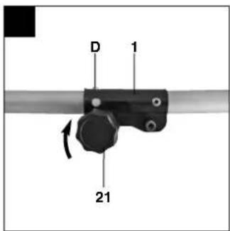
Remove the transport guard cap from the lower long handle. Undo the handle screw (Fig. 4a/Item 21) on the connecting piece of the upper long handle (1). Carefully slide the lower long handle (2) into the connecting piece on the upper long handle. When doing so, take care to ensure that the drive shafts on the insides of the long handles slide into each other (turn the spool head gently, if required) and that the lock on the lower long handle (Fig. 4b/Item D) latches securely in the connecting piece. Now retighten the handle screw (21). To dismantle, proceed in reverse order.
6.1.2 Fitting the guard hood
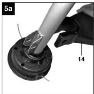
Attach the guard hood to the lower long handle (Fig. 5a). Screw the guard hood tightly in position with the screw set (16) (Fig. 5b).
6.1.3 Fitting the carrying strap (Fig. 1)
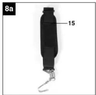
The carrying strap is intended to help you work safely and ergonomically with the power trimmer. Hook the carrying strap into the fastening eyelet (Fig. 1/Item 24).
Check that all moving parts move smoothly before you start using the equipment. Check that all screws are securely fastened and also check all the safety devices.
6.1.4 Fitting the additional handle (Fig. 3a-3c)
Slacken the nut on the fastening screw on the handle (Fig. 3a/Item 17). Remove the nut and the fastening screw (Fig. 3a/Item 17) from the handle and insert them in the long handle (2). Then screw the handle to the long handle.
6.2 Setting the cutting height
- Slip the shoulder strap (Fig. 8a) over the left shoulder.
- Set the length of the shoulder strap in such a way that the cutting head runs parallel to the ground. In order to establish the optimum length of the shoulder strap, you should then make a few swinging movements without starting the engine (Fig. 9a).
Important: Always use the strap when working with the equipment. Attach the strap as soon as you have started the engine and it is running in idle mode. Switch off the engine before you take off the carrying strap.
Check the equipment for the following each time before use:
● That there are no leaks in the fuel system.
- That the equipment is in perfect condition and that the safety devices and cutting devices are complete.
● That all screws are securely fastened.
● That all moving parts move smoothly.
6.3 Fuel and oil
Recommended fuels
Use only a mixture of unleaded petrol and special 2-stroke engine oil. Mix the fuel mixture as indicated on the fuel mixing table.
Important: Do not use a fuel mixture which has been stored for longer than 90 days.
Important: Never use 2-stroke oil with a recommended mixing ratio of 100:1. The manufacturer's warranty will be voided in case of engine damage due to inadequate lubrication.
Important: Only use containers designed and approved for the purpose to transport and store fuel. Pour the correct quantities of petrol and 2-stroke oil into the mixing bottle (see scale printed on the bottle). Then shake the bottle well.
6.4 Fuel mixture table
Mixing procedure: 40 parts petrol to 1 part oil
| Petrol 2-stroke | oil |
| 1 liters 25 ml | |
| 5 liters 125 ml |
7. Operation
Please note that the statutory regulations governing noise abatement may differ from town to town.
7.1 Starting the engine when cold
Fill the tank with the required amount of oil/petrol mix. See "Fuel and oil".
- Set the equipment down on a hard, level surface.
-
Press the fuel pump (primer) (Fig. 1/Item 7) 10 times.
-
Move the ON/OFF switch (Fig. 1/Item 9) to "I"
-
Set the choke lever (Fig. 1/Item 5) to "
-
Hold the equipment firmly and pull out the starter cable (Fig. 1/Item 4) until you feel it start to resist. Then tug sharply on the starter cable 4 times. The equipment should start.
Important: Never allow the starter cable to snap back. This may damage the equipment.
Important: Since the choke lever is secured, the cutting tool starts to operate when the engine is started.
Then release the choke lever by actuating it once. (The engine returns to its idle state).
- If the engine does not start up, repeat steps 4-5 above.
Please note: If the engine does not start up even after several attempts, read the section "Engine Troubleshooting". Please note: Always pull the starter cord out in a straight line. If it is pulled out at an angle, then friction will occur on the eyelet. As a result of this friction, the cable will become frayed and will wear away faster. Always hold the starter handle when the cable retracts. Never allow the cable to snap back when it has been pulled out.
7.2 Starting the engine when warm
(The equipment has been idle for less than 15-20 min.)
- Set the equipment down on a hard, level surface.
- Switch the ON/OFF switch to "I".
- Hold the equipment firmly and pull out the starter cable until you feel it start to resist. Then tug sharply on the starter cable. The equipment should start after 1-2 tugs. If the equipment does not start after 6 pulls, repeat steps 1 to 6 of the
GB
procedure for starting the engine from cold.
7.3 Switching off the engine
Emergency Stop procedure:
If it becomes necessary to stop the equipment immediately, set the ON/OFF switch to "Stop" or "0"
Normal procedure:
Let go of the throttle lever and wait until the engine has changed to idling speed. Then set the ON/OFF switch to "Stop" or "0".
7.4 Practical tips
Practice all operating techniques with the engine switched off before you start to use the equipment.
Extending the cutting line
Warning! Do not use any kind of metal wire or metal wire encased in plastic in the line spool. This may cause serious injuries to the user. To extend the cutting line run the engine at full speed and tap the line spool on the ground. This will automatically extend the line. The blade on the safety shield will cut the line to the appropriate length (Fig. 9b).
Important: Remove all grass and weed remains at regular intervals to prevent the shaft tube overheating. Grass and weed remains become trapped under the safety shield (Fig. 9c) and they prevent the shaft tube receiving adequate ventilation. Remove the remains carefully using a screwdriver or the like.
Different cutting methods
If the equipment is correctly assembled it will cut weeds and long grass in places with difficult access, for example along fences, walls and foundations and also around trees. It can also be used for mowing work to remove vegetation to allow the better preparation of a garden or to clear a certain area down to the soil.
Please note: Even if it is used carefully, cutting around foundations, stone or concrete walls, etc. will result in the line suffering above normal wear.
Trimming/mowing
Swing the trimmer from side to side in a scything motion. Always keep the line spool parallel to the ground. Check the site and decide what cutting height you require. Guide and hold the line spool at the required height to ensure that you cut evenly (Fig. 9d).
Low trimming
Hold the trimmer right in front of you at a slight angle so that the underside of the line spool is above the ground and the line strikes the correct target. Always cut away from yourself. Never draw the trimmer towards yourself.
Cutting along fences/foundations
When cutting approach wire mesh fences, lath fences, natural stone walls and foundations slowly so that you can cut close to them without striking the obstacle with the line. If, for example, the line strikes stones, stone walls or foundations, it will wear or fray. If the line strikes wire fencing it will break.
Trimming around trees
When trimming around tree trunks, approach slowly so that the line does not strike the bark. Walk around the tree, cutting from left to right. Approach grass or weeds with the tip of the line and tilt the line spool forwards slightly. Warning: Take extreme care during mowing work. When doing such work keep a distance of 30 meters between yourself and other people or animals.
Mowing
For mowing you want to cut all the vegetation down to the ground. To do this, set the line spool at an angle of 30^ to the right. Place the handle in the required position. Remember the increased risk of injury to the user, watchers and animals and the danger of damaging other items due to objects (for example stones) being thrown out (Fig. 9e).
Warning: Do not remove any objects from footpaths, etc. using the equipment.
The equipment is a powerful tool and can throw small stones and other objects a distance of 15 meters or more, causing injuries and damage to cars, houses and windows.
Sawing
The equipment is not suitable for sawing.
8. Cleaning, maintenance and ordering of spare parts
Always switch off the equipment and pull out the spark boot plug before carrying out any maintenance work.
8.1 Replacing the line spool / cutting line
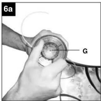
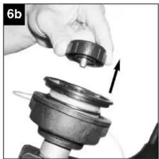
- Unscrew the retainer screw (Fig. 6a/Item G) in a counter-clockwise direction and remove (Fig. 6b). If you fail to do this by hand, use the key (Fig. 2/Item 10).
- Remove the spool (Fig. 6c/Item H) and the spring (Fig. 6c/Item I) from the spindle (Fig. 6c/Item J).
The following steps only have to be carried out if only the line and not the entire spindle requires replacing:
- Remove the remaining cutting line from the spool.
-
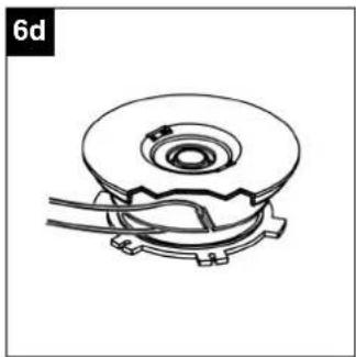
Hold the two halves of a new cutting line together in the middle and place the loop in one of the slots on the spool divider (Fig. 6d).
● Wind the line with tension in a counter-clockwise direction as shown in the illustration (Fig. 6e), with the two halves being separated by the spool divider. Wind up all of the line down to the last 15cm of each end. -
Fasten each of the ends of the line in a slot (Fig. 6f/Item L) on the opposite side of the spool.
- Fit the springs on the inside of the spool and thread each of the ends of the line through one of the eyelets in the spool holder (Fig. 6c/Item K).
- Insert the spool in the spool holder. Make sure that the spring slides over the spindle and does not get stuck.
- Press the spool into the spool holder with your hand and use your other hand to fasten the retainer screw tightly (Fig. 6g).
- Give each end of the line a strong tug to pull the line out of the slots.
- Cut off all excess line to reduce it to approx. 13 cm. This will reduce the load on the engine when starting up and warming up.
8.2 Servicing the air filter
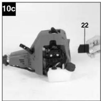
Soiled air filters reduce the engine output by supply too little air to the carburetor. Regular checks are therefore essential. The air filter (22) should be checked after every 25 hours of use and cleaned if necessary. If the air contains a lot of dust, the air filter should be checked more frequently.
- Remove the air filter cover (Fig. 10a).
- Remove the air filter (Fig. 10b/10c)
- Clean the air filter by tapping it or blowing it.
- Assemble in reverse order.
Important: Never clean the air filter with petrol or inflammable solvents.
8.3 Maintenance of the spark plug
Spark plug sparking gap = 0.6mm. Tighten the spark plug with a torque of 12 to 15 Nm. Check the spark plug for dirt and grime after 10 hours of operation and if necessary clean it with a copper wire brush. Thereafter service the spark plug after every 50 hours of operation.
-
Pull out the spark plug boot.
-
Remove the spark plug (Fig. 11b) with the supplied spark plug wrench (19).
-
Assemble in reverse order.
8.4 Grinding the safety hood blade
The safety hood blade (Fig. 7a/Item R) can become blunt over time. When you notice this, undo the screw holding the safety hood blade to the safety hood. Clamp the blade in a vise. Sharpen the blade with a flat file and make sure that the angle of the cutting edge is not altered in the process. File in one direction only.
8.5 Carburetor settings
Important. Settings on the carburetor may only be made by authorized customer service personnel. The air filter cover must be removed before any work on the carburetor, as shown in Figures 10a and 10b.
Setting the throttle cable
If the maximum speed of the equipment falls over time and you have ruled out all the other causes listed in section 11 Troubleshooting, it may be necessary to adjust the throttle cable.
First of all check whether the carburetor opens fully when the throttle handle is pressed fully. This is the case if the lever M impacts against the carburetor housing when the throttle is fully open (Fig. 12a). Figure 12a shows the correct setting. If the lever M does not impact against the carburetor housing, it must be adjusted.
The following work is required to adjust the throttle cable:
● Undo the lock nut (Fig. 12b/Item N) a few turns.
- Undo the adjusting screw (Fig. 12b/Item O) until the lever M impacts fully against the housing when the throttle is fully activated, as shown in Figure 12a.
● Retighten the lock nut.
GB
Setting the idling speed
Important. Set the idling speed when the equipment is warm.
If the engine stalls when the throttle is not pressed and you have ruled out all the other causes listed in section 11 Troubleshooting, the idling speed must be adjusted. To do this turn the idling speed screw (Fig. 12b/Item P) clockwise until the equipment runs smoothly at idling speed. If the idling speed is so fast that the cutting tool turns as well, it has to be reduced by turning the idling speed screw for as long as is required for the cutting tool to stop turning as well.
8.6 Environmental protection
Dispose of soiled maintenance material and operating materials at the appropriate collection point. Recycle packaging material, metal and plastics.
8.7 Ordering replacement parts
Please provide the following information on all orders for spare parts:
● Model/type of the equipment
● Article number of the equipment
● ID number of the equipment
- Spare part number of the required spare part For our latest prices and information please go to www.isc-gmbh.info
9. Storage and transport
9.1 Storage
Important: Never put the equipment into storage for longer than 30 days without carrying out the following steps.
Storing the equipment
If you intend to store the equipment for longer than 30 days, the equipment must be prepared accordingly. Otherwise the fuel still remaining in the carburetor will evaporate and leave a rubbery sediment. This can cause problems when starting up the equipment and may require expensive repairs.
- Slowly remove the fuel tank cap to release any pressure that may have formed in the tank. Carefully empty the tank.
- Start the engine and let it run until the equipment stops in order to remove any fuel from the carburetor.
- Leave the engine to cool (approx. 5 minutes).
- Remove the spark plug (8.3).
- Add one teaspoon of 2-stroke engine oil into the combustion chamber. Slowly pull the starter cord several times to apply a layer of oil to all internal components. Fit the spark plug again.
Note: Store the equipment in a dry place and far away from possible ignition sources such as an oven, a gas-fired hot water boiler, a gas-fired dryer, etc.
Putting the equipment back into operation
- Remove the spark plug (8.3).
- Quickly tug on the starter cord to remove excess oil from the combustion chamber.
- Clean the spark plug and check that the electrode gap is correct.
- Prepare the equipment for operation.
- Fill the tank with the relevant mixture of fuel and oil. See the section entitled "Fuel and oil".
9.2 Transport
To transport the equipment, empty the petrol tank as described in the section entitled "Storage". Clean coarse dirt off the equipment with a brush or hand brush. Dismantle the steady grip as described in section 6.1.4.
10. Disposal and recycling
The equipment is supplied in packaging to prevent it from being damaged in transit. The raw materials in this packaging can be reused or recycled. The equipment and its accessories are made of various types of material, such as metal and plastic. Defective components must be disposed of as special waste. Ask your dealer or your local council.
- Troubleshooting
| Fault Possible cause | Troubleshooting | |
| The machine does not start. Correct | starting procedure not followed. | Follow the instructions for starting. |
| Sooted or damp spark plug Clean the spark plug or replace it with a new one. | ||
| Incorrect carburetor setting Contact | an authorized customer service outlet or send the machine to ISC-GmbH. | |
| The machine starts but does not develop its full output. | Incorrect choke lever setting Set choke lever to “” ♦ | |
| Soiled air filter Clean the air filter | ||
| Incorrect carburetor setting Contact | an authorized customer service outlet or send the machine to ISC-GmbH. | |
| The engine does not run smoothly Incorrect electrode gap on the spark plug | Clean the spark plug and adjust the electrode gap or fit a new spark plug. | |
| Engine smokes excessively Incorrect fuel mix Use the correct fuel mix (see fuel mixing table) | ||

Sommaire
Premer nitke - ∅ 2,0 mm
X 2006/42/EC
□ Annex IV
Notified Body:
Reg. No.:
X 2000/14/EC_2005/88/EC
X Annex V
□ Annex VI
Noise: measured L_WA = 106.9 dB (A); guaranteed L_WA = 112 dB (A) P = 0,6 kW; L/∅ = cm Notified Body:
X 2012/46/EU_(EU)2016/1628
Emission No.: e24*2016/1628*2017/656SHA1/P*0115*00 (v)
Standard references: EN ISO 11806; EN ISO 14982
Subject to change without notice
Archive-File/Record: NAPR019257
Documents registrar: Jehl Markus
Wiesenweg 22, D-94405 Landau/Isar

natural_image
Symbol of a trash bin crossed with a diagonal line, representing no waste or discharge (no text or numbers present)© Nur für EU-Länder
Never place any electric tools in your household refuse.
To comply with European Directive 2012/19/EC concerning old electric and electronic equipment and its implementation in national laws, old electric tools have to be separated from other waste and disposed of in an environment-friendly fashion, e.g. by taking to a recycling depot.
Recycling alternative to the demand to return electrical devices:
As an alternative to returning the electrical device, the owner is obliged to cooperate in ensuring that the device is properly recycled if ownership is relinquished. This can also be done by handing over the used device to a returns center, which will dispose of it in accordance with national commercial and industrial waste management legislation. This does not apply to the accessories and auxiliary equipment without any electrical components which are included with the used device.
The reprinting or reproduction by any other means, in whole or in part, of documentation and papers accompanying products is permitted only with the express consent of ISC GmbH.
F
All of our products undergo strict quality checks to ensure that they reach you in perfect condition. In the unlikely event that your device develops a fault, please contact our service department at the address shown on this guarantee card. You can also contact us by telephone using the service number shown. Please note the following terms under which guarantee claims can be made:
- These warranty terms regulate additional warranty services, which the manufacturer mentioned below promises to buyers of its new products in addition to their statutory rights of guarantee. Your statutory guarantee claims are not affected by this guarantee. Our guarantee is free of charge to you.
-
The warranty services cover only defects due to material or manufacturing faults on a product which you have bought from the manufacturer mentioned below and are limited to either the rectification of said defects on the product or the replacement of the product, whichever we prefer. Please note that our devices are not designed for use in commercial, trade or professional applications. A guarantee contract will not be created if the device has been used by commercial, trade or industrial business or has been exposed to similar stresses during the guarantee period.
-
The following are not covered by our guarantee:
- Damage to the device caused by a failure to follow the assembly instructions or due to incorrect installation, a failure to follow the operating instructions (for example connecting it to an incorrect mains voltage or current type) or a failure to follow the maintenance and safety instructions or by exposing the device to abnormal environmental conditions or by lack of care and maintenance. - Damage to the device caused by abuse or incorrect use (for example overloading the device or the use or unapproved tools or accessories), ingress of foreign bodies into the device (such as sand, stones or dust, transport damage), the use of force or damage caused by external forces (for example by dropping it). - Damage to the device or parts of the device caused by normal or natural wear or tear or by normal use of the device.
-
The guarantee is valid for a period of 24 months starting from the purchase date of the device. Guarantee claims should be submitted before the end of the guarantee period within two weeks of the defect being noticed. No guarantee claims will be accepted after the end of the guarantee period. The original guarantee period remains applicable to the device even if repairs are carried out or parts are replaced. In such cases, the work performed or parts fitted will not result in an extension of the guarantee period, and no new guarantee will become active for the work performed or parts fitted. This also applies if an on-site service is used.
-
Please report the defective device on the following internet address to register your guarantee claim: www.isc-gmbh.info. If the defect is covered by our guarantee, then the item in question will either be repaired immediately and returned to you or we will send you a new replacement device.
Of course, we are also happy offer a chargeable repair service for any defects which are not covered by the scope of this guarantee or for units which are no longer covered. To take advantage of this service, please send the device to our service address.
Also refer to the restrictions of this warranty concerning wear parts, consumables and missing parts as set out in the service information in these operating instructions.
F BULLETIN DE GARANTIE
Chère Cliente, Cher Client,

[Non-Text]
[Non-Text]
[Non-Text]
[Non-Text]
[Non-Text]


- ⚠️ Important.
- Safety information
- CAUTION
- Safety devices
- Layout (Fig. 1-12)
- Items supplied
- IMPORTANT
- GB
- Intended use
- Technical data
- Sound and vibration
- Wear ear-muffs.
- Functions
- Reduce noise generation and vibration to a minimum!
- Before starting the equipment
- Assembly
- Fitting the long handle (Fig. 4a-4b)
- Fitting the guard hood
- Fitting the carrying strap (Fig. 1)
- Fitting the additional handle (Fig. 3a-3c)
- Setting the cutting height
- Fuel and oil
- Fuel mixture table
- Operation
- Starting the engine when cold
- Starting the engine when warm
- Switching off the engine
- Emergency Stop procedure:
- Normal procedure:
- Practical tips
- Extending the cutting line
- Different cutting methods
- Trimming/mowing
- Low trimming
- Cutting along fences/foundations
- Trimming around trees
- Mowing
- Sawing
- Cleaning, maintenance and ordering of spare parts
- Replacing the line spool / cutting line
- Servicing the air filter
- Maintenance of the spark plug
- Grinding the safety hood blade
- Carburetor settings
- Setting the throttle cable
- Setting the idling speed
- Environmental protection
- Ordering replacement parts
- Storage and transport
- Storage
- Storing the equipment
- Putting the equipment back into operation
- Transport
- Disposal and recycling
- Sommaire
- Standard references: EN ISO 11806; EN ISO 14982
- F
- F BULLETIN DE GARANTIE
- Chère Cliente, Cher Client,
Brand : EINHELL
Model : GCPT 25381 I AS
Category : Brush cutter