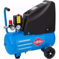
HLO 21525 - Compressor Airpress - Free user manual and instructions
Find the device manual for free HLO 21525 Airpress in PDF.



| Product type | Air compressor |
| Brand | Airpress |
| Model | HLO 21525 |
| Dimensions (L x W x H) | 580 x 325 x 560 mm |
| Weight | 23 kg |
| Power supply | 230 V / 50 Hz |
| Motor power | 1.1 kW (1.5 HP) |
| Tank capacity | 25 liters |
| Operating pressure | 6 bar |
| Maximum pressure | 8 bar |
| Air flow | 215 L/min |
| Noise level | 78 dB(A) |
| Intermittent duty | 30% per hour (max. 18 min/h) |
| Ambient temperature range | +5°C to +40°C |
| Pressure adjustment | Pressure regulator with pressure gauge |
| Automatic stop/restart | Yes, pressure switch 6-8 bar |
| Condensate drain | Tap under the tank |
| Air filter | Cleanable by blowing out |
| Safety valve | Yes, integrated |
| Use | Indoors only |
| Warranty | 12 months |
| Compliance | CE (directives 98/37/EC, 89/336/EC, 73/23/EC, 2000/14/EC) |
Frequently Asked Questions - HLO 21525 Airpress
User questions about HLO 21525 Airpress
0 question about this device. Answer the ones you know or ask your own.
Ask a new question about this device
Download the instructions for your Compressor in PDF format for free! Find your manual HLO 21525 - Airpress and take your electronic device back in hand. On this page are published all the documents necessary for the use of your device. HLO 21525 by Airpress.
USER MANUAL HLO 21525 Airpress
Operating instructions
1.0 Prefatory note page 14
2.0 Safety instructions page 15
3.0 Placing page 16
3.1 Electric connection page 16
3.2 Air connection page 17
4.0 First use page 17
5.0 Operation page 17
6.0 Maintenance page 18
7.0 Possibilities of failure page 19
8.0 Technical details page 19
LEGENDA Fig. 1 (subject to modification)
A manual pressure switch
B reducing valve setting
C push bow
D coupling reduced pressure receiver
E safety valve
F bonnet for engine and fan
G non return valve
H gauge reduced pressure
I plug for extra connection
J pressure gauge for pressure of air
K drain tap for condensation water
L air filter
M discharge line
N pressure pipe
O cable with plug
ATTENTION
To be able to use this compressor installation properly, a number of measurements must be taken. The following points will contribute to making you a satisfied user of this installation.
1.0 PREFATORY NOTES
Buying this compressor installation, you have become the owner of a compressor installation with a high performance and reliability level. Correct use and regular maintenance will increase the life of the compressor. n this manual you will find operation and maintenance instructions. Read it carefully and keep it as a guide to your compressor.
The compressor has been built to supply compressed air. In particular the appliance cannot be used to produce air to be breathed by humans or used on direct contact with foodstuffs. The appliance must be used only for the purpose for which it was
specifically designed. All other uses are to be considered incorrect and therefore unreasonable. The manufacturer cannot be held responsible for any damage resulting from improper, incorrect or unreasonable use. This machine is not suitable for external installation.
2.0 SAFETY INSTRUCTIONS
Important: please read and observe the following safety instructions before using the machine.
- Nobody must be allowed to use the compressor unless they have read the instruction manual and have been instructed in the regulations to follow for correct and safe use.
- The machine must be used by adults only. Use of the compressor by apprentices of not less than 16 years of age must be supervised by an adult authorised to use the machine.
- Keep children and visitors away from the working area.
- Be cautious when using compressed air. Never aim the air flow at people or animals. Do not use compressed air to clean clothing.
- Compressed air is not suitable to inhale.
- Do not wear loose clothing or neckties that can get caught in moving parts. Preferably wear safety goggles, nonslip footwear and Wear protective hair covering to contain long hair.
- Only use the machine outside in dry, well-ventilated surroundings and do not expose the machine to rain.
- The compressor should be placed in such way that all points, destined to carry it will really do so. Take also care of a horizontal position.
- This machine is not fit for continuous running, but service for 30% per 60 minutes.
- Keep your work area clean and well lighted.
- Do not use the machine in areas where fumes from paint, solvents or flammable liquids pose a potential hazard.
- Do not exceed the maximum operating pressure and only use the machine in an ambient temperature between +5^ and +40^ .
- Never attempt to tamper with the protections of the log splitter or to operate the machine without these.
- The working parts of the machine can become hot during operation. Let the machine cool down after use.
- After each use the tank must be vented and the moisture collected in the tank must be bled. Not bleeding the tank can lead to leakage and may cause a dangerous situation.
- Check that the electric circuit is adequately protected and that it corresponds with the power, voltage and frequency of the motor. Check that there is a ground connection and a regulation differential switch upstream.
- Use cables with an adequate section and avoid use of free and inadequately insulated connections.
- Never open the pushbutton box on the motor. Should this be necessary, contact
a qualified electrician.
- Make sure that the machine and the cable never come in contact with water.
- Treat the power cable with care. Do not attempt to move the machine by pulling the cable. Do not yank the cable to unplug it; keep the cable away from excessive heat, oil and sharp objects.
-
Never leave the machine unattended with the power supply "on". Also disconnect the power cable when:
-
you leave the machine, even for a short time
- not in use
- carrying out maintenance work
-
changing attachment or moving the machine.
-
WARNING: the warnings, cautions and instructions discussed in this instruction manual cannot cover all possible conditions and situations that may occur. It must be understood by the operator that common sense and caution are factors which cannot be built into this product, but must be supplied by the operator.
- Only those persons who are aware of how to use the compressor by having read this manual, should use the machine. Injudicious use may cause danger.
Danger plates (see page 32)
The plates fitted on the compressor unit are part of the machine; they have been applied for safety purposes and must not be removed or spoiled for any reason.
3.0 PLACING
The compressor should be placed in such way that all points, destined to carry it will really do so. Take also care of a horizontal position. The engine should get sufficient cooling air; so never cover the ventilating openings.
Place the compressor in a cool dustfree space. Never place the compressor in a room where will be sprayed. Paint spray will clog the air filter and will also deposit on the compressor.
Mind that the drain tap for condensation water (K) will always remain attainable. We suggest to leave a space of approximately 30~cm for ventilation and maintenance.
Notice: Insufficient air supply, too high temperature and fouling of the air filter reduce the efficiency of the compressor considerably.
3.1 ELECTRIC CONNECTION
At the factory the machine is already fully equipped with cables. The machine now has to be connected to your own electricity supply. Connect the machine to a separate group. Beware that voltage and amperage of your electric circuit meet the needs of the motor. Use only cables with the right diameter. The factory suggests to use cables of at least 2.5 qmm.
Before first use first read chapters 3.2 and 4.0.
3.2 AIR CONNECTION
Best use for connection of the compressor to an air circuit a flexible hose, to isolate vibrations from the machine.
4.0 FIRST USE
- Check if the instructions mentioned above have been executed.
- Installing the air filter (L): before use you have to install the supplied air filter in the cylinder head. Remove the dust cap and screw the air filter (L) in.
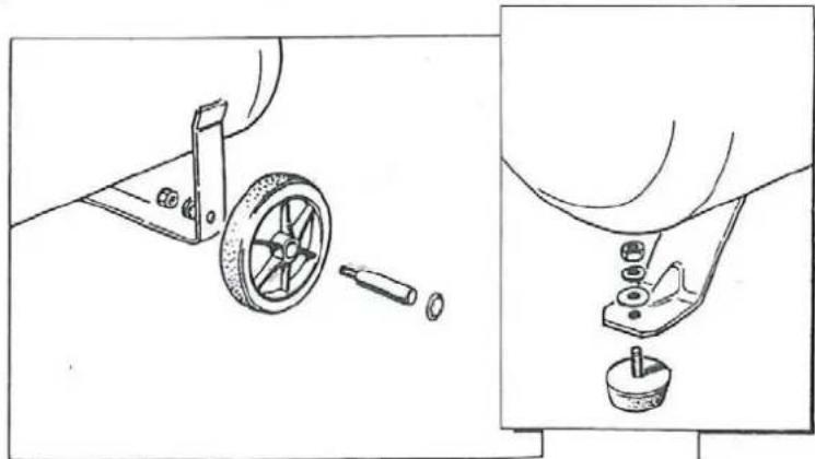
- Assemble wheels + vibration damper in accordance with drawing:
- Switch on the compressor by means of the pressure switch (A). The compressor will now operate, unless the air receiver is still under pressure (K). Switch the machine, during operation, exclusively off by means of the button on the automatic pressure switch (A); the pressure circuit will be vented and the compressor can start again uncharged.
- Avoid the use of extension cables. If you use them, unroll them completely and use cables of sufficient capacity. Table for extension cables:
0 - 10 meter: 3 × 1 1/2 mm^2
10 - 25 meter: 3 × 2 1/2 ~mm^2
5.0 OPERATION
- The automatically operating compressor will stop at a pressure of 8 bar. When air is used again and the pressure in the tank falls to 6 bar, the compressor will start again.
- Most pneumatic machines are suitable for an operating pressure of about 6 bar. For some applications this pressure is even lower. To be able to set the right pressure, the compressor is provided with a reducing valve (B). This valve can set the pressure of the air receiver (of course never higher than the pressure in the air receiver).
- The setting of the reducing valve is done as follows: Switch the button to set the right pressure (to the left to lower the pressure, to the right to increase it). The pressure gauge (H) shows the pressure.
- Two extra plugs (I) are fitted to the tank, which can be used to get an extra pressure connection.
6.0 MAINTENANCE
Before carrying out any maintenance jobs it is obligatory to stop the machine and disconnect it from the power mains.
- Regularly drain condensation water. The drain tap (K) is situated at the bottom of the tank. Draining with pressure in the tank is the easiest way.
- The air filter element (L) should be cleaned or changed regularly. This change depends on the amount of fouling and should be done more often in dusty situations and less often in a clean situation. For cleaning the filter element, take out the filter container with the filter. Then clean the filter by blowing off the dust.
Note: Regular maintenance of your compressor will increase durability and reliability.
MAINTENANCE TABLE
| works weekly monthly | |
| draining condensation water | |
| clean air filter |
After use shut down the compressor by pushing the button on the automatic pressure switch and then pull the plug from the power supply.
7.0 POSSIBILITIES OF FAILURE
1 Compressor does not run at starting pressure:
*blown fuse - renew the fuse
tank at pressure - discharge
motor broken - repair/renew
* defective pressure switch - repair/renew
2 Repeating thermal failure:
*blown fuse - renew fuse
* loose wire - repair
pressure switch does not release - repair/renew valve air circuit
too low voltage - remove extension cable or use heavier
* overloading - reduce loading
3 Compressor keeps blowing off air:
- defective non-return valve - repair/renew
4 Too little air production:
- dirty air filter - clean/renew filter
- defective valves - renew
5 Leaking safety valve:
- pressure too high - set pressure switch
- defective safety valve - renew
8.0 TECHNICAL DETAILS
Operating pressure 6 bar
Maximum pressure 8 bar
Sound pressure 78 dB(A)
Service 30% per hour
Air intake capacity 215 l/min.
Weight 23 kg
Dimensions (lwxh) 580× 325× 560mm
Model changes reserved.
FRANÇAIS
TABLE DES MATIERES
Sous reserve de modifications.
ESPAGNOL
INDICE
The plates fitted on the compressor unit are part of the machine; they have been applied for safety purposes and must not be removed or spoiled for any reason.
Waste electrical products should not be disposed of with household waste. Please recycle where facilities exist. Check with your Local Authority or retailer for recycling advice.
(F)
Seller's signature Firmstamp seller
For claims against the guarantee, please send us the machine/the apparatus with the completed guarantee certificate and invoice free of charge.
Land/Land/Country/Pays/Pais
GARANTIEBEPALINGEN
The machine/apparatus supplied carries a 12 month guarantee, starting from the day of purchase. If any breakdowns occur within this period, caused by material or structural defects, this guarantee will cover parts as well as labour costs. This guarantee will not cover claims if:
- The instructions in this manual have not been observed.
- The machine / apparatus has been modified in such a way that it no longer functions properly, not even when damaged parts are replaced with the proper components.
- Damage is due to frost, dropping, impact, unauthorized disassembly, improper connection to the electricity grid etc.
- Damage is due to the use of extension leads thinner than 2,5mm^2 (only 230 volts).
If the guarantee claim is accepted, the machine/apparatus will be repaired and returned free of charge. No other damages will be paid.
CONDITIONS DE GARANTIE
EC-declaration of conformity
We, Airpress, P.O. Box 114, 8900 AC Leeuwarden, The Netherlands, taking full responsibility, declare that the products
compressors HLO 215/25
to which this declaration refers, comply with the machinery directive 98/37/EC, the EMC directive 89/336/EC, the low tension directive 73/23/EC and the directive 2000/14/EC.
The Netherlands, Leeuwarden, 24th July 2006
Operating instructions
- LEGENDA Fig. 1 (subject to modification)
- ATTENTION
- PREFATORY NOTES
- SAFETY INSTRUCTIONS
- Important: please read and observe the following safety instructions before using the machine.
- Danger plates (see page 32)
- PLACING
- ELECTRIC CONNECTION
- AIR CONNECTION
- FIRST USE
- OPERATION
- MAINTENANCE
- MAINTENANCE TABLE
- POSSIBILITIES OF FAILURE
- Compressor does not run at starting pressure:
- Repeating thermal failure:
- Compressor keeps blowing off air:
- Too little air production:
- Leaking safety valve:
- TECHNICAL DETAILS
- FRANÇAIS
- TABLE DES MATIERES
- ESPAGNOL
- INDICE
- (F)
- GARANTIEBEPALINGEN
- CONDITIONS DE GARANTIE
- EC-declaration of conformity
- compressors HLO 215/25
- Operating instructions
Brand : Airpress
Model : HLO 21525
Category : Compressor