Inserto 70 Ventilato H49 - Pan La Nordica - Free user manual and instructions
Find the device manual for free Inserto 70 Ventilato H49 La Nordica in PDF.
| Product type | Wood insert (wood stove) |
| Brand | La Nordica |
| Model | Inserto 70 Ventilato H49 |
| Fuel | Dry wood (max humidity 20%) |
| Nominal power | 9 kW |
| Efficiency | 79.7% |
| Flue gas temperature | 289 °C |
| CO emissions | 0.11% |
| Air supply | Primary and secondary air adjustable |
| Draft type | Chimney with flue (draught 11-14 Pa) |
| Ventilation | Integrated tangential fans (forced convection) |
| Door | Panoramic glass-ceramic door (resists up to 700°C) |
| Firebox material | Cast iron and steel |
| Ash drawer | Yes, removable even during operation |
| Controls | Primary air, secondary air, flue valve register |
| Power supply | 230 V ~ 50 Hz (for fans) |
| Safety distance (front) | 80 cm (reducible to 40 cm with protection) |
| Floor protection | Fireproof slab at least 12 cm if combustible floor |
| Minimum flue section | 4 dm² (20 x 20 cm) for diameter < 200 mm |
| Maintenance | Regular cleaning of glass, ash drawer, flue |
| Warranty | Use of original parts mandatory (refer to dealer) |
Frequently Asked Questions - Inserto 70 Ventilato H49 La Nordica
User questions about Inserto 70 Ventilato H49 La Nordica
0 question about this device. Answer the ones you know or ask your own.
Ask a new question about this device
Download the instructions for your Pan in PDF format for free! Find your manual Inserto 70 Ventilato H49 - La Nordica and take your electronic device back in hand. On this page are published all the documents necessary for the use of your device. Inserto 70 Ventilato H49 by La Nordica.
USER MANUAL Inserto 70 Ventilato H49 La Nordica
natural_image
Technical line drawing of a rectangular industrial enclosure with two circular top fixtures and a central opening (no text or symbols)
natural_image
Technical line drawing of a mechanical enclosure or enclosure with three circular components and a central panel (no text or symbols)
natural_image
Technical line drawing of a mechanical enclosure or enclosure with three circular components and internal compartments (no text or symbols)Testata secondo / Tested according to / Geprüft nach / Certifié selon / : EN13229

text_image
Warning symbol image with exclamation mark inside triangleIT - PER EVITARE DANNI ALL'APPARECCHIO, RISPETTARE IL CARICO ORARIO DI COMBUSTIBILE INDICATO NEL PRESENTE LIBRETTO.
EN - TO AVOID DAMAGES TO THE APPLIANCE, PLEASE RESPECT THE MAX. FUEL QUANTITY (KG/HR) INDICATED IN THE USER'S MANUAL.
SAFETY REGULATIONS ON THE APPLIANCES
To meet safety regulations, it is compulsory to install and use our products carefully following the instructions contained in this manual.
DECLARATION OF CONFORMITY OF THE MANUFACTURER
Object: Absence of asbestos and cadmium
We declare that the materials used for the assembly of all our appliances are without asbestos parts or asbestos derivates and that in the material used for welding, cadmium is not present, as prescribed in relevant norm.
Object: CE n. 1935/2004 regulation.
We declare that in all products we produce, the materials which will get in touch with food are suitable for alimentary use, according to the a.m. CE regulation.
natural_image
Technical line drawing of a mechanical clamp or bracket assembly with an arrow indicating motion (no text or symbols present)IT - INDICE
-
AVVERTENZE GENERALI 7
-
NORME PER L'INSTALLAZIONE....7
-
SICUREZZA ANTINCENDIO....7
3.1. PRONTO INTERVENTO....8
-
FERMO ESTIVO....13
-
MANUTENZIONE E CURA....14
12.1. PULIZIA VETRO ....14
12.2. PULIZIA CASSETTO CENERE 14
12.3. PULIZIA CANNA FUMARIA....14
-
GENERAL PRECAUTIONS .... 15
-
INSTALLATION REGULATIONS ....15
-
FIRE-FIGHTING SAFETY MEASURES....15
3.1. FIRST-AID MEASURES....16
3.2. BEAM PROTECTIONS....16
-
TECHNICAL DESCRIPTION....16
-
FLUE....17
5.1. CHIMNEY CAP 17
5.2. CONNECTION TO THE FLUE / AIR FOR COMBUSTION (external air intake)....17
5.3. EXTERNAL AIR INTAKE....18
-
VENTILATION HOOD OR ADJACENT LOCAL 18
-
CONNECTION AND MAINTENANCE OF VENTILATION....19
-
ALLOWED / NOT ALLOWED FUELS....19
-
LIGHTING....20
9.1. LOW EMISSION fire lighting....20
- NORMAL OPERATION 21
10.1. OPERATION DURING TRANSITION PERIODS 21
-
SUMMER STOP....21
-
MAINTENANCE AND CARE....22
12.1. GLASS CLEANING....22
12.2. CLEANING OUT THE ASHES 22
12.3. CLEANING THE FLUE 22
-
CALCULATION OF THE THERMAL POWER....22
-
Seires VENTILATION....45
-
OPTIONAL VENTILATION KIT 1318000 46
-
DIMENSIONS SHEETS......48
-
TECHNICAL DATA SHEET 50
La NORDICA S.p.A. responsibility is limited to the supply of the appliance.
The installation must be carried out scrupulously according to the instructions provided in this manual and the rules of the profession. Installation must only be carried out by a qualified technician who works on behalf of companies suitable to assume the entire responsibility of the system as a whole.
La NORDICA S.p.A. declines any responsibility for the product that has been modified without written authorisation as well as for the use of non-original spare parts.
This appliance is not suitable for the use of inexperienced people (included children) or with physical, sensorial and mental reduced capacities. They have to be controlled and educated in the use of the appliance from a responsible person for their security. The children have to be controlled to be sure that they would not play with the appliance. (EN 60335-2-102/7.12).
It is OBLIGATORY to respect the National and European rules, local regulations concerning building matter and also fireproof rules.
NO MODIFICATIONS CAN BE CARRIED OUT TO THE APPLIANCE. La NORDICA S.p.A. cannot be held responsible for lack of respect for such precautions.
2. INSTALLATION REGULATIONS
Installation of the product and auxiliary equipment in relation to the heating system must comply with all current Standards and Regulations and to those envisioned by the law.
The installation and the relating to the connections of the system, the commissioning and the check of the correct functioning must be carried out in compliance with the regulations in force by authorised professional personnel with the requisites required by the law, being national, regional, provincial or town council present in the country within which the appliance is installed, besides these present instructions.
Installation must be carried out by authorised personnel who must provide the buyer with a system declaration of conformity and will assume full responsibility for final installation and as a consequence the correct functioning of the installed product.
Before installing the appliance, carry out the following checks:
- Make sure that the floor can support the weight of the appliance, and if it is made of flammable material, provide suitable insulation (DIMENSIONS ACCORDING TO REGIONAL REGULATIONS). With a flammable floor the appliance must be installed on a 12 cm thick stone or concrete slab.
- Make sure that there is adequate ventilation in the room where the appliance is to be installed.
- Do not install the appliance in rooms containing collective ventilation ducts, hoods with or without extractor, type B gas appliances, heat pumps, or other appliances that, operating at the same time, can put the room in depression (ref. UNI 10683 standard)
- Make sure that the flue and the pipes to which the appliance will be connected are suitable for its operation.
- The diameter of the opening for connection to the chimney must at least correspond to the diameter of the flue gas pipe. The opening must be equipped with a wall connection for the insertion of the exhaust pipe and a rosette.
• Always leave the recommended air pocket between the appliance and the walls, rear and side min. (see MARKING INFORMATION). - Establish the type of ventilation (natural or forced) see chapter VENTILATION HOOD OR ADJACENT LOCAL.
- By means of the adjustable feet and using a level make sure that the device is perfectly levelled to allow a correct sliding of the door.
After testing the proper working of the appliance, some days from the installation, it is possible to proceed with the construction of its aesthetic covering.
WARNING: During the surround building operations it must kept in mind possible and subsequent electrical installed parts maintenance (Fans, temperature probe, etc) and with hydraulic systems all parts connected to the product.
La NORDICA S.p.A. declines all responsibility for damage to things and/or persons caused by the system. In addition, it is not responsible for any product modified without authorisation and even less for the use of non original spare parts.
Your regular local chimney sweep must be informed about the installation of the appliance so that he can check the correct connection to the chimney.
3. FIRE-FIGHTING SAFETY MEASURES
When installing the appliance, the following safety measures must be observed:
a) In order to ensure sufficient thermal insulation, respect the minimum safety distance from objects or furnishing components flammable and sensitive to heat and from materials with flammable structure (see CE MARKING INFORMATION). All the minimum safety distances are shown on the product data plate and lower values must not be used.
b) in front of the furnace door, in the radiation area, there must be no flammable or heat-sensitive objects or material at a distance of less than 80 cm. This distance can be reduced to 40 cm where a rear-ventilated, heat-resistant protection device is installed in front of the whole component to protect;
c) If the product is installed on a no totally refractory floor, one must foresee a fireproof background. The floors made of inflammable material, such as moquette, parquet or cork etc., must be replaced by a layer of no-inflammable material (size according to regional law). In case the replacement of the floor is not possible, the appliance shall be placed on a minimum 12 cm thick slab made of stone or concrete (see Picture 1 at page 39).
The ash drawer must always be inserted when the appliance is in operation.
The solid combustion residues (ashes) must be collected in a metal container that is hermetically sealed and fire resistant. The appliance must never be lit in the presence of gaseous emissions or vapours (for example: glue for linoleum, petrol, etc.). Do not place flammable materials in the vicinity of the appliance.
During the combustion, thermal air is emitted by involving the heating of areas, door and glass hearth, of the door handles or controls, of the smokes pipe and, in case, of the front part of appliance. Avoid to touch those parts without a protective clothing or without accessory tools (gloves resistant to heat, control devices).
Ensure children are aware of these dangers and keep them away from the furnace when it is on.
Warn children that the device becomes very hot and that it must not be touched.
When using the wrong fuel or one which is too damp, due to deposits present in the flue, a flue fire is possible.
3.1. FIRST-AID MEASURES
Should any fire arise in the stack or in the flue:
a) Close the feeding door.
b) Close the registers of combustion air
c) Extinguish the fire using carbon dioxide fire-fighting means (CO _2 dust).
d) Seek immediate intervention of FIRE BRIGADE.
DO NOT EXTINGUISH FIRE USING WATER JETS. When the flue does not burn any more please arrange an examination by a specialist in order to find possible cracks and permeable points.
3.2. BEAM PROTECTIONS
Considering the irradiation of the hearth, it is necessary to be particularly careful in protecting the beams while designing your stack. Consider the proximity of beams to the external surfaces of the hearth, on one side, and the irradiation of the glass door, usually very close to the beams, on the other side. In any case, it has to be considered that the internal or lower surfaces of this beam in flammable material must not come in contact with temperatures higher than 65 °C. Picture 2 at page 39 gives some examples of execution.
WARNING: We cannot be made liable for a wrong operation of the plant, when it does not comply with the provisions of these instructions or when it uses additional products not suitable for this device.
4. TECHNICAL DESCRIPTION
The appliance is made up of a series of cast-iron elements joined to one another by a fixed joint, while the seal is assured by refractory putty. The assembly is supported by tie rods and nuts located outside the heating body and coated with a carter made of varnished and galvanized sheet heat-resistant.
The appliances are equipped with an integrated air circuit for the recovery of the heat made up of deflectors (radiant fins) on all external surfaces of the heating body. The appliances are equipped with a hearth with double thickness part.
The appliance works as an intermittent operating appliance.
The insert is equipped with a sight door with ceramic glass (resistant up to 700^ C). This allows a charming sight on burning flames. Moreover, in this way, any possible leak of sparks and smoke is avoided. Under the hearth grating there is a easily extractable ash drawer, also when the appliance works.
The heating of the room occurs:
a) by convection: the passage of air through the coating and the covering hood releases heat in the room.
b) by radiation: through the sight glass and the steel body, heat is radiated into the room.
The device is equipped with registers of primary and secondary air, with which it is possible to adjust the combustion air.
1A - PRIMARY air register (Picture 8 at page 43)
With the air register located under the door of the hearth (on the left), it is possible to adjust the air flow through the ash drawer and the grating in direction of the fuel. The primary air is necessary for the combustion process during the ignition. When the knob is completely on the left, the register is closed, when the knob is completely on the right the register is opened.
The ash drawer has to be emptied regularly, so that ash cannot hinder the intake of primary air for the combustion. Primary air is also necessary to keep fire live.
During the combustion of wood, the primary air register must be opened only a few, since otherwise the wood burns quickly and the device can overheat (see chapter NORMAL OPERATION).
2A - SECONDARY air register (Picture 8 at page 43)
On the door of the hearth to the right, there is a secondary air register.
This valve must be opened (and therefore shifted to the right), in detail, for the combustion of wood, so that unburnt carbon can be subject to a post-combustion, increasing the yield and assuring the cleaning of the glass (see chapter NORMAL OPERATION).
3 - Smoke valve register
Combustion is not always regular; as matter of fact both atmospheric conditions and outside temperature can influence it by modifying the depression in the stack. For this reason, all inserts are equipped with an adjustable smoke valve with automatic opening allowing an optimal adjustment of the draught.
Through the lever located on the bottom left, it is possible to position the smoke valve correctly (all to the left = all open). Should the door open independently from its position, the smoke valve opens automatically.
The adjustment of the registers necessary to reach the rated calorific yield is the following one:
| Hourly consumption (kg/h) | PRIMARY AIR SE | CONDARY AIR TERTIARY AIR | Smoke valve register | |
| INSERTO 60 | 2 | CLOSED OPENED NO CLOSED | ||
| INSERTO 70 | 2,6 | CLOSED OPENED NO CLOSED | ||
5. FLUE
Essential requirements for a correct operation of the device:
- the internal section must be preferably circular;
- be thermally insulated and water-proof and produced with materials suitable to resist to heat, combustion products and possible condensates;
- not be throttled and show a vertical arrangement with deviations not greater than 45^ ;
- if already used, it must be clean;
- observe the technical data of the instructions manual;
Should the flues have a square or rectangular section, internal edges must be rounded with a radius not lower than 20 mm. For the rectangular section, the maximum ratio between the sides must be = 1.5.
A too small section causes a decrease of the draught. It is suggested a minimum height of 4 m.
The following features are forbidden and therefore they endanger the good operation of the device: asbestos cement, galvanized steel, rough and porous internal surfaces. In Picture 3 at page 39 gives some examples of execution.
The minimum section must be 4 dm ^2 (for example 20 x 20 cm) for devices whose duct diameter is lower than 200 mm or 6.25 dm ^3 (for example 25 x 25 cm) for devices with diameter greater than 200 mm.
The draught created by the flue must be sufficient, but not excessive.
A too big flue section can feature a too big volume to be heated and consequently cause difficulties in the operation of the device; to avoid this, tube the flue along its whole height. A too small section causes a decrease of the draught.
ATTENTION: as far as concern the realisation of the flue connection and flammable materials please follow the requirements provided by UNI 10683 standard. The flue must be properly spaced from any flammable materials or fuels through a proper insulation or an air cavity. It is FORBIDDEN to let plant piping or air feeding channels pass in the same flue. Moreover, it is forbidden to create movable or fixed openings on the same for the connection of further other devices (Picture 4 at page 40).
5.1. CHIMNEY CAP
The draught of the flue depends also on the suitability of the chimney cap.
Therefore, if it is handicraft constructed, the output section must be more than twice as big as the internal section of the flue. Should it be necessary to exceed the ridge of the roof, the chimney cap must assure the discharge also in case of windy weather (Picture 5 at page 40 - Picture 6 at page 41).
The chimney cap must meet the following requirements:
• have internal section equivalent to that of the stack.
• have a useful output section twice as big as the flue internal one.
- be manufactured in such a way as to prevent the penetration of rain, snow, and any other foreign body in the flue.
- be easily checkable, for any possible maintenance and cleaning operation
5.2. CONNECTION TO THE FLUE / AIR FOR COMBUSTION (external air intake)
The connection to the stack must be performed with stiff pipes in steel comply with all current Standards and Regulations and to those envisioned by the Law.
It is FORBIDDEN to use metallic pipes or pipes in asbestos cement since they jeopardize the safety of the fitting itself, considering that they are subject to tears or breaks resulting in leaks of smoke.
The exhaust pipe must be air-tight fastened to the stack and can have a maximum inclination of 45^ ; this to avoid excessive deposits of condensate produced in the initial start-up phases and/or the excessive gripping of soot and moreover it avoids the slowing down of the smokes at output.
The failed tightness of the connection can cause the malfunction of the device.
The internal diameter of the connection pipe must be equal to the external diameter of the smokes stub pipe of the device. This is assured by the pipes complying with DIN 1298.
For a better working of the appliance, it is suggested to have a flue draught of 11 Pa14 Pa (=1.1=1.4 mm of column of water).
The measurement has always to be carried out with hot device (rated thermal performance).
When the depression exceeds 17 Pa (=1.7 mm of column of water), it is necessary to reduce the same by installing an additional draught
regulator (butterfly valve).
IMPORTANT: When using metallic pipes, they must be insulated with proper materials (coatings in insulating fibers resistant up to 600°C) in order to avoid deterioration of walls or of the counter-hood.
Before positioning the insert in the pre-existing fireplace, it is necessary to close the upper internal part of the stack using (properly pre-drilled) sheet metal or any other kind of fire-resistant material that can support very high temperatures without suffering any damage. (see Picture 7 at page 42 pos. 1 Inserti).
It is necessary to ventilate continuously the space included between the upper part, the sides of the device and the deflector of the fire-proofing material of the hood.
For this reason, it is necessary to foresee an intake of air from the bottom (intake of fresh air) and a high output (output of hot air).
Each of these openings must be free and it should not be possible to obstruct it; moreover, they must have a minimum surface of at least 3 dm^2 (example: 30 × 10 cm grating).
In this way, the following targets are achieved:
- a greater safety
- an increase of the heat created by air circulation around the device.
The heat vent grating (Picture 7 at page 42 pos. 6) has to be installed on the upper part of the hood at about 20 cm from the roof. This must always be installed since its function is that of letting the heat collected within the hood (overpressure) flow out into the room.
5.3. EXTERNAL AIR INTAKE
There MANDATORY be sufficient quantity of air for combustion and re-oxygenation of the room to ensure the device will work properly. There should therefore be vents letting air in from outside the building and enabling circulation of air for combustion even when the doors and windows are closed.
- The air intake must be in a position where it cannot be obstructed.
- The air intake should communicate with the room in which the device is installed and be protected with a grille.
• Vents may communicate with adjacent rooms but NOT with garages, kitchens, bathrooms or boiler rooms (FORBIDDEN). - Any extractor hoods in the room where the device is installed must not operate at the same time as this could cause smoke to enter the room, even with the fireplace's door closed.
• Minimum dimensions (See chapter TECHNICAL DATA)
6. VENTILATION HOOD OR ADJACENT LOCAL
Our products are equipped with tangential fans suitable to improve the distribution of heat through the ventilation exclusively of the installation room (see chapter SERIES VENTILATION).
On our products, it is possible to install OPTIONAL ventilation kits suitable to improve the distribution of heat by ventilation only either of the installation room or of the adjacent local (see chapter OPTIONAL VENTILATION KIT).
The product can distribute heated air by natural convection or forced convection by means of a centrifugal fan (OPTIONAL); therefore, during installation, it is necessary to establish the type of ventilation or convection to be adopted.
The covering of each product is equipped with 2 outputs with a diameter of 120 mm (12 cm) for the connection of pipes resistant to heat.
a) Perform the drilling on the walls or on the existing hood to allow the passage and the application of the (fire-resistant) hoses with related openings.
b) Fasten the pipes by means of clamps to the related collars and openings, after having removed the semi-blanks caps (see Picture 10 at page 43).
c) Each pipe must not exceed 1.5 m of length for natural ventilation and 4 m for forced ventilation; it must be insulated with insulating materials to avoid noise and dispersion of heat.
d) The openings have to be positioned at a height not lower than 2 m from the floor to avoid that hot air at output meets people. Please respect the distance of the convection openings according to the local construction norms;
e) The lengths of the canalization pipes must have the same length to avoid the distribution of differing quantities of air from each output (see Picture 10 at page 43).
f) If the space between the upper part of the insert and the lower profile of the hood is lower than 10 cm, it is necessary to perform a hole of about 30 x 40 cm on the hood to allow the fastening of the hoses;
g) The OPTIONAL ventilation kit has to be installed below the appliance in the rear part (see instructions in chapter OPTIONAL kit ventilation). As a consequence you should arrange a underlying space to collocate it, allowing a proper air flow and the accessibility for future maintenance.
7. CONNECTION AND MAINTENANCE OF VENTILATION
Our products are equipped with tangential fans suitable to improve the distribution of heat through the ventilation exclusively of the installation room (see SERIES VENTILATION chapter TECHNICAL DATA SHEET).
The lighting and the adjustment is carried out through the proper standard supplied control unit that has to be installed far from any direct heat source.
The selection of the kind of insert to be connected is in the control unit and has to be done by moving the small bridge as shown hereafter (see chapter SERIES VENTILATION) before the INSERT starts to operate. This operation must be done without electric energy!!
On our products, it is possible to install OPTIONAL ventilation kits suitable to improve the distribution of heat by ventilation only either of the installation room or of the adjacent local (see chapter VENTILATION HOOD OR ADJACENT LOCAL). For the connection of the ventilation kit, please see chapter OPTIONAL VENTILATION KIT.
The Kit is made up of a centrifugal fan, a lighting and adjustment control unit, and a (TM) thermostat that lets the fan start when the device is properly heated and lets it stop when the fan is partially cold.
The control unit and the plant must be installed and connected by authorized personnel according to the standards in force (see chapter GENERAL PRECAUTIONS).
ATTENTION: the control unit and the feeding cable must not be in contact with hot parts (Picture 11 at page 44).
CONNECTION: Connect the power supply cable of the control unit to a bipolar switch respecting at least a 3 mm distance between the contacts (power supply 230 V\~50 Hz, it is necessary to provide for the correct connection to the grounding plant). This operation must be done without electric energy!!
WARNING: The COMMAND must be connected to the mains with a differential line cut-off switch according to the regulations in force. Correct operation of the command is assured only for the proper motor for which it has been manufactured. Improper use relieves the manufacturer from each responsibility.
8. ALLOWED / NOT ALLOWED FUELS
Allowed fuels are logs. Use exclusively dry logs (max. content of water 20%). Maximum 3 logs should be loaded. The pieces of wood should have a length of ca. 20-30 cm and a maximum circumference of 30-35 cm.
Compressed not worked-out wood briquettes must be used carefully to avoid overheating that may damage the device, since these have a very high calorific value.
The wood used as fuel must have a humidity content lower than the 20% and must be stored in a dry place. Humid wood tends to burn less easily, since it is necessary a greater quantity of energy to let the existing water evaporate. Moreover, humid content involves the disadvantage that, when temperature decreases, the water condensates earlier in the hearth and therefore in the stack causing a remarkable deposit of soot with following possible risk of fire of the same.
Fresh wood contains about 60% of H_2O , therefore it is not suitable to be burnt.
It is necessary to place this wood in a dry and ventilated place (for example under a roofing) for at least two years before using it.
Besides others, it is not possible to burn: carbon, cuttings, waste of bark and panels, humid wood or wood treated with paints, plastic materials; in this case, the warranty on the device becomes void.
Paper and cardboard must be used only to light the fire.
The combustion of waste is FORBIDDEN and would even damage the appliance and the flue, causing health damages and claims by the neighborhood owing to the bad smell. The wood is not a fuel which allows a continuous operation of the appliance, as consequence the heating all over the night is not possible.
| Variety kg/mc kWh/kg moistness 20% | ||
| Beech | 750 4,0 | |
| Oak | 900 4,2 | |
| Elm | 640 4,1 | |
| Poplar | 470 4,1 | |
| Larch* | 660 4,4 | |
| Spruce* | 450 4,5 | |
| Scots pine * | 550 4,4 | |
* RESINOUS WOOD NOT SUITABLE FOR THE BURNING
ATTENTION : the continuous and protracted use of aromatic wood (eucalyptus, myrtle etc.) quickly damages the cast iron parts (cleavage) of the product.
9. LIGHTING
After the first ignition you can smell bad odours (owing to the drying of the glue used in the garnitures or of the paint) which disappear after a brief using of the appliance. A good ventilation of the room should always be guaranteed.
T light the fire, it is suggested to use small wood pieces together with paper or other traded lighting means.
It is FORBIDDEN to use any liquid substance as for ex. alcohol, gasoline, oil and similar.
Open the primary air completely.
When wood starts to burn, it is possible to feed it again by opening slowly the door, in order to avoid leaks of smoke, and close the primary air register and control the combustion through the secondary air register according to the provisions of chapter TECHNICAL DESCRIPTION. Please always be present during this phase.
Never overload the appliance (see the technical table - max. quantity of fuel that can be loaded / hourly consumption).
Too much fuel and too much air for combustion can cause overheating and therefore damage the same.
Never switch on the device when there are combustible gases in the room.
To perform a correct first lighting of the products treated with paints for high temperature, it is necessary to know the following information:
- the construction materials of the involved products are not homogeneous, in fact there are simultaneously parts in cast iron, steel, refractory material and majolica;
- the temperature to which the body of the product is subject is not homogeneous: from area to area, variable temperatures within the range of 300°C - 500°C are detected;
- during its life, the product is subject to alternated lighting and extinguishing cycles in the same day, as well as to cycles of intense use or of absolute standstill when season changes;
- the new appliance, before being considered seasoned has to be subject to many start cycles to allow all materials and paints to complete the various elastic stresses;
- in detail, initially it is possible to remark the emission of smells typical of metals subject to great thermal stress, as well as of wet paint. This paint, although during the manufacture it is backed at 250 °C for some hours, must exceed many times and for a given period of time the temperature of 350 °C before becoming completely embedded in the metallic surfaces.
Therefore, it is extremely relevant to take these easy steps during the lighting:
- Make sure that a strong air change is assured in the room where the appliance is installed.
- During the first starts, do not load excessively the combustion chamber (about half the quantity indicated in the instructions manual) and keep the product continuously ON for at least 6-10 hours with the registers less open than the value indicated in the instructions manual.
- Repeat this operation for at least 4-5 or more times, according to your possibilities.
- Then load more and more fuel (following in any case the provisions contained in the installation booklet concerning maximum load) and, if possible, keep the lighting periods long avoiding, at least in this initial phase, short ON/OFF cycles.
- During the first starts, no object should be leaned on the appliance and in detail on enamelled surfaces. Enamelled surfaces must not be touched during heating.
- Once the «break-in» has been completed, it is possible to use the product as the motor of a car, avoiding abrupt heating with excessive loads.
After testing the proper working of the appliance, some days from the installation, it is possible to proceed with the construction of its aesthetic covering.
WARNING: During the surround building operations it must kept in mind possible and subsequent electrical installed parts maintenance (Fans, temperature probe, etc) and with hydraulic systems all parts connected to the thermo-fireplace.
9.1. LOW EMISSION fire lighting
Smokeless combustion is a way of lighting a fire able to significantly reduce the emission of harmful substances. The wood burns gradually from the top downwards, so combustion is slower and more controlled. Burnt gases pass through the high temperatures of the flame and therefore burn almost completely.
Place the logs in the hearth a certain distance apart as shown in the Picture 9 at page 43. Arrange the largest at the bottom and the smallest at the top, or vertically in the case of tall narrow combustion chambers. Place the fire starter module on top of the pile, arranging the first logs in the module at right angles to the pile of wood.
Fire STARTER MODULE
This fire starter module replaces a paper or cardboard starter.
Prepare four logs, 20 cm long with a cross section of 3 cm by 3 cm Picture 9 at page 43. Cross the four logs and place them on top of the pile of wood at right angles, with the fire lighter (wax impregnated wood fibre for example) in the middle. The fire can be lit with a match. If you want, you can use thinner pieces of wood. In this case, you will need a larger quantity.
Keep the flue gas exhaust valve and combustion air regulator open (1A - 2A). After lighting the fire, leave the combustion air regulator open in the position shown in the Picture 9 at page 43.
IMPORTANT:
- do not add further wood between one complete load and the next;
- do not suffocate the fire by closing the air intakes;
- regular cleaning by a chimney sweep reduces fine particle emissions.
These instructions are backed by ENERGIA Legno SVIZZERA www.energia-legno.ch
After having positioned the registers correctly, insert the indicated hourly wood load avoiding overloads that cause anomalous stresses and deformations. You should always use the product with the door closed in order to avoid damages due to overheating (forge effect). The inobservance of this rule makes the warranty expire.
With the registers located on the front of the device, it is possible to adjust the heat emission of the same. They have to be opened according to the calorific need. The best combustion (with minimum emissions) is reached when, by loading the wood, most part of the air for combustion flows through the secondary air register.
Never overload the appliance. Too much fuel and too much air for the combustion may cause overheating and then damage the product.
You should always use the appliance with the door closed in order to avoid damages due to overheating (forge effect).
The adjustment of the registers necessary to reach the rated calorific yield with a depression at the stack of 11 Pa 14 Pa (=1.1 =1.4 mm of column of water) is the following one: see chap. TECHNICAL DESCRIPTION. The appliance works as an intermittent operating appliance.
Besides the adjustment of the air for the combustion, the intensity of the combustion and consequently the thermal performance of the device is influenced by the stack. A good draught of the stack requires a stricter adjustment of air for combustion, while a poor draught requires a more precise adjustment of air for combustion.
To verify the good combustion, check whether the smoke coming out from the stack is transparent.
If it is white, it means that the device is not properly adjusted or the wood is too wet; if instead the smoke is gray or black, it signals that the combustion is not complete (it is necessary a greater quantity of secondary air).
WARNING: When fuel is added onto the embers in the absence of a flame, a considerable amount of fumes may develop. Should this happen, an explosive mixture of gas and air may form, and in extreme cases an explosion may occur. For safety reasons it is advisable to perform a new lighting procedure with the use of small strips.
10.1. OPERATION DURING TRANSITION PERIODS
During transition periods when the external temperatures are higher, if there is a sudden increase of temperature it can happen that the combustion gases inside the flue cannot be completely sucked up.
The exhaust gases do not come out completely (intense smell of gas). In this case, shake the grating more frequently and increase the air for the combustion. Then, load a reduced quantity of fuel in order to permit a rapid burning (growing up of the flames) and the stabilization of the draught.
Then, check that all openings for the cleaning and the connections to the stack are air-tight. In case of doubt, do not operate the product.
11. SUMMER STOP
After cleaning the hearth, chimney and hood, totally eliminating the ash and other eventual residues, close all the doors of the hearth and the relevant registers; in case you disconnect the appliance from the chimney you must close its openings in order to let work others possible appliances connected to the same flue.
We suggest performing the cleaning operation of the flue at least once per year; verifying in the meantime the actual status of the rope seals, which cannot ensure the good operation of the equipment if they are not in good condition and are not making a good seal! In this case the seals must be replaced.
In presence of dampness in the room where the stove has been placed, we advise you to put absorbent salts into the hearth.
If you want to keep for long the aesthetic look of the cooker it is important to protect its internal walls in row cast iron with neutral Vaseline.
12. MAINTENANCE AND CARE
Check the external air intake, by cleaning it, at least once a year. The stack must be regularly swept by the chimney sweeper.
Let your chimney sweeper in charge of your area check the regular installation of the device, the connection to the stack and the aeration.
IMPORTANT: The maintenance must be carried out only and exclusively with cold device. You should only use spare parts approved and supplied by La NORDICA S.p.A. . Please contact your specialized retailer if you require spare parts. YOU MUST NOT MAKE ANY CHANGES TO THE DEVICE!!!
12.1. GLASS CLEANING
Thanks to a specific inlet of secondary air, the accumulation of dirty sediments on the glass-door is reduced with efficacy. Nevertheless this can never be avoided by using solid fuels (particularly wet wood) and it has not to be understood as a defect of the appliance.
IMPORTANT: The cleaning of the sight glass must be carried out only and exclusively with cold device to avoid the explosion of the same. For the cleaning, it is possible to use specific products or a wet newspaper paper ball passed in the ash to rub it. Do not use cloths, abrasive or chemically aggressive products by cleaning the hearth glass.
The correct lighting phase, the use of proper quantities and types of fuels, the correct position of the secondary air regulator, enough draught of the chimney-flue and the presence of combustion air are the essential elements for the optimal functioning of the appliance and for the cleaning of the glass.
BREAK OF GLASSES: Given that the glass-ceramic glasses resist up to a heat shock of 750^ C, they are not subject to thermal shocks. Their break can be caused only by mechanic shocks (bumps or violent closure of the door, etc.). Therefore, their replacement is not included in the warranty.
12.2. CLEANING OUT THE ASHES
All the devices are equipped with a hearth grating and an ash drawer for the collection of the ashes.
It is suggested to empty periodically the ash drawer and to avoid it fills completely in order not to overheat the grating. Moreover, it is suggested to leave always 3-4 cm of ash in the hearth.
CAUTION: The ashes removed from the hearth have to be stored in a container made of fire-resistant material equipped with an air-tight cover. The container has to be placed on a fire-resistant floor, far from flammable materials up to the switching off and complete cooling.
12.3. CLEANING THE FLUE
The correct lighting phase, the use of proper quantities and types of fuels, the correct position of the secondary air regulator, enough draught of the chimney-flue and the presence of combustion air are the essential elements for the optimal functioning of the appliance.
The device should be completely cleaned at least once a year or every time it is a needed (in case of bad working and low yield). An excessive deposit of soot can cause problems in the discharge of smokes and fire in the flue.
The cleaning must be carried out exclusively with cold equipment. This operation should be carried out by a chimney sweeper who can simultaneously perform an audit of the flue (checking of possible deposits).
13. CALCULATION OF THE THERMAL POWER
There is not an absolute rule for calculating the correct necessary power. This power is given according to the space to be heated, but it depends also largely on the insulation. On an average, the calorific value necessary for a properly insulated room is 30 kcal/h per m³ (for an external temperature of 0°C).
Given that 1 kW corresponds to 860 kcal/h, it is possible to adopt a value of 38 W/m ^4 .
Let's suppose one wishes to heat a room of 150m^3 (10 x 6 x 2.5 m) in an insulated apartment. In this case, it is necessary to have 150m^3 x 38 W/m ^3 = 5700 W or 5,7 kW. As main heating, a 8 kW device is therefore sufficient.
| Approximate combustion value Re | required quantity in relation to 1 kg of dry wood | |||
| Fuel Unit kcal/h kW | ||||
| Dry wood (15% humidity) kg 3600 4.2 | 1,00 | |||
| Wet wood (50% humidity) | kg 1850 2.2 1,95 | |||
| Wood briquettes | kg 4000 5.0 0,84 | |||
| Brown coal briquettes | kg 4800 5.6 0,75 | |||
| Normal anthracite | kg 7700 8.9 0,47 | |||
| Coke | kg 6780 7.9 0,53 | |||
| Natural gas | m^3 | 7800 9.1 0,46 | ||
| Naphtha | L | 8500 9.9 0,42 | ||
| Electricity | kW/h | 860 | 1.0 4,19 | |
2. INSTALLATIONSVORSCHRIFTEN
8. COMBUSTIBLES ADMIS / NON ADMIS
natural_image
Architectural cross-section diagram showing structural components and floor levels (no text or labels)| A | Rappresentazione di canna fumaria corretta con sportello a tenuta per la raccolta e lo scarico dei materiali solidi incombusti.Representation of a correct flue with air-tight door for the collection and discharge of solid unburnt materials.Darstellung eines richtigen Schornsteinrohres mit dichter Tür für die Sammlung und Entleerung von ungebrannten Festmaterialen.Représentation de conduit de fumée correcte avec porte étanche pour la récolte et déchargement des matériaux solides non brûlés. |
| B | Sconsigliato il collegamento alla canna fumaria di più apparecchi. Ciascuno deve poter usufruire di una propria canna fumaria.The connection of more than one device to the flue is not recommended. Each device must have its own flue.DE - (Ja - ist zulässig)Déconseillée la connexion au conduit de fumée de plusieurs appareils. Chacun doit pouvoir se servir de son propre conduit de fumée. |
| 1 | Sportello per la pulizia.Door for cleaning.Reinigungstür.Porte pour nettoyage. |
5
1

2

3
text_image
50 cm4

natural_image
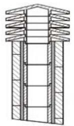
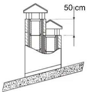
Simple line drawing of a house with a cross symbol crossed over a textured base (no text or labels)| 1 | Comignolo industriale ad elementi prefabbricati, consente un ottimo smaltimento dei fumi.Industrial chimney cap with pre-fabricated elements – it allows an excellent discharge of the smokesIndustrialschornstein mit Fertigteilelemente - er gestattet eine ausgezeichnete Abgasentsorgung.Tête de cheminée industrielle à éléments préfabriqués, elle permet une excellente évacuation des fumées. |
| 2 | Comignolo artigianale. La giusta sezione di uscita deve essere minimo 2 volte la sezione interna della canna fumaria, ideale 2,5 volte.Handicraft chimney cap. The right output section must be at least twice as big as the internal section of the flue (ideal value: 2.5 times).Handwerklicher Schornstein. Der richtige Ausgangsquerschnitt muss mindestens 2 Male des Innenquerschnittes des Schornsteinrohrs betragen, ideal wäre: 2,5 Male.Tête de cheminée artisanale. La juste section de sortie doit être minimum 2 fois la section interne du conduit de fumée, idéal 2,5 fois. |
| 3 | Comignolo per canna fumaria in acciaio con cono interno deflettore dei fumi.Chimney cap for steel flue with internal cone deflector of smokes.Schornstein für Schornsteinrohr aus Stahl mit einer Kegelförmigen Rauchumlenkplatte.Tête de cheminée pour conduit de fumée en acier avec cône interne déflecteur des fumées. |
| 4 | In caso di canne fumarie affiancate un comignolo dovrà sovrastare l'altro d'almeno 50 cm al fine d'evitare trasferimenti di pressione tra le canne stesse.In case of flues side by side, a chimney cap must be higher than the other one of at least 50 cm in order to avoid pressure transfers between the flues themselves.Im Falle von naheliegenden Schornsteinrohren muss ein Schornstein den anderen um mindestens 50cm überragen, um Druckübertragungen unter den Schornsteinrohren selbst zu vermeiden.En cas de conduits de cheminée à côté, une tête de cheminée devra surmonter l'autre d'au moins 50 cm dans le but d'éviter transferts de pression parmi les conduits mêmes. |

text_image
6 2 m 10 m 1 m 55
The chimney cap must not show hindrances within 10 m from walls, pitches and trees. Otherwise raise it of at least 1 m over the hindrance. The chimney cap must exceed the ridge of the roof of at least 1 m.
text_image
Technical diagram of a mechanical device with numbered components and directional arrows indicating flow or movement.INSERTI
| 1* | Chiusura del condotto esistente con lamiera, mattoni, pannelli di lana di roccia o materiali ignifughiClosure of the existing duct with sheet metal, bricks, mineral wool panels or fire resistant materialsVerriegelung der vorhandenen Rohrleitung mit Blech, Backsteinen, Gesteinswolletafeln oder feuerfeste MaterialenFermeture du conduit existant avec tôle, briques, panneaux de laine de roche ou matériaux ignifugesCierre del conducto existente con chapa, ladrillos, paneles de lana de roca o materiales ignífugosFecho da conduta existente com chapa, tijolos, painéis de lã de vidro ou materiais ignífugos |
| 2 | Griglia - Grating - Gitter - Grille - Rejilla - Grelha |
| 3 | Condotto di collegamento - Connection duct - Verbindungsrohrleitung - Conduit de connexion - Conducto de conexión - Conduta de ligação |
| 4 | Condotto - Duct - Rohrleitung - Conduit - Conducto - Conduta |
| 5 | Griglia di entrata aria - Air intake grating - Lufteinlassgitter - Grille d'entrée air - Rejilla de entrada de aire - Grelha de entrada de ar |
| 6 | Distanze laterall e posterioriRear and side distancesMindestabstand zwischen Verkleidung und EinsatzDistance min. latéral entre revêtement |
8

text_image
3 1A 2A9
MODULO DI ACCENSIONE
FIRE STARTER MODULE
ANFEUERMODUL
MODE D'ALLUMAGE

text_image
20 3 3
text_image
2A - On10

text_image
A A
natural_image
Technical line drawing of an air duct system with coiled pipes and a control panel (no text or symbols)11
natural_image
Line drawing of a kitchen appliance with a control panel and wiring, no text or symbols present| ALIMENTAZIONEPOWER SUPPLYSTROMVERSORGUNGALIMENTATIONALIMENTACIÓNALIMENTAÇÃO | 230 V~ +15 – 10% 50 Hz |
| DIMENSIONIDIMENSIONSABMESSUNGENDIMENSIONSDIMENSIONESDIMENSOES | 120 x 74 x 51 mm |
| CONTENITORECONTAINERBEHÄLTERRECIPIENTCONTENEDORCONTENTOR | ABS autoestinguente IP40 V0Self-extinguishing ABS IP40 V0ABS selbstlöschend IP40 V0ABS autoéteignant IP40 V0ABS autoextinguible IP40 V0ABS auto-extinguível IP40 V0 |
- VENTILAZIONE di SERIE . Seires VENTILATION . LÜFTUNG - Schon dabei . VENTILATION DU SERIE

text_image
20 mm INTERRUTTORE BIPOLARE BIPOLAR SWITCH ZWEIPOLIGER SCHALTER INTERRUPTEUR BIPOLAIRE 7 MODEL Ph N M M 4 52 631 Ph N M M ALIMENTAZIONE 230V~ 50Hz TM M| 1 | Blu - AlimentazioneBlue - Power supplyBlau - StromversorgungBlue - Alimentation |
| 2 | Marrone - AlimentazioneBrown - Power supplyBraun - StromversorgungBrown - Alimentation |
| 3 | Giallo/verde - Alimentazioneyellow/green - Power supplyGelb /Grün - Stromversorgungjaune/vert - Alimentation [IMAGE] |
| 4 | Giallo/verde - Motoreyellow/green - MotorGelb /Grün - Motorkabejaune/vert - Moteur [IMAGE] |
| 5 | Blu - Motore - TermostatoBlue - Motor - ThermostatBlau - Motorkabel - ThermostatkabelBlue - Moteur - Thermostat |
| 6 | Marrone - MotoreBrown -MotorBraun - MotorkabelBrown -Moteur |
| 7 | PonticelloJumper |
TM=TERMOSTATO MINIMA

text_image
7 I-50 I-70 I-60 I-80 I-100 AIR FAN-MOTOR I-50 I-70 I-60 I-80 I-100 AIR FAN-MOTOR15. KIT VENTILAZIONE OPZIONALE 1318000 . OPTIONAL VENTILATION KIT 1318000
. EXTRA KIT GEBLÄSE 1318000 . KIT VENTILATION EN OPTION 1318000

| 1 | Blu - AlimentazioneBlue - Power supplyBlau - StromversorgungBlue - Alimentation |
| 2 | Marrone - AlimentazioneBrown - Power supplyBraun - StromversorgungBrown - Alimentation |
| 3 | Blu - MotoreBlue - MotorBlau - MotorkabelBlue - Moteur |
| 4 | Marrone - MotoreBrown -MotorBraun - MotorkabelBrown -Moteur |
| 5 | Giallo/verde - Motoreyellow/green - MotorGelb /Grün - Motorkabejaune/vert - Moteur |
| 6 | Giallo/verde - Alimentazioneyellow/green - Power supplyGelb /Grün - Stromversorgungjaune/vert - Alimentation |
| 7 | Blu - TermostatoBlue - ThermostatBlau - ThermostatkabelBlue - Thermostat |
| 8 | Marrone - TermostatoBrown - ThermostatBraun - ThermostatkabelBrown - Thermostat |
BIPOLAR SWITCH
ZWEIPOLIGER SCHALTER
INTERRUPTEUR BIPOLAIRE

text_image
1130087 1130087 TM 1318000 AT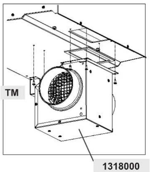
text_image
TM 1318000ATTENZIONE: collegare ermeticamente. NON FORNITO
ATTENTION : hermetic connect. NOT SUPPLIED
ACHTUNG : hermetisch verbinden. NICHT IM LIEFERUMFANG
ATTENTION : Joindre hermétiquement. NE PAS FOURNIS

text_image
190 53 TM 213 265
text_image
Ø130 190 51 51 260 170 260- DIMENSIONI . DIMENSIONS SHEETS . MAße . DIMENSIONS

text_image
595 500
text_image
112 246 142
text_image
490 Ø 160 148 220 440 Ø 120 102.5 195 195 102.5INSERTO 60 VENTILATO

text_image
695 550
text_image
119 250 181
text_image
590 Ø 160 Ø 120 158 225 450 112.5 235 235 112.5INSERTO 70 VENTILATO

text_image
695 495
text_image
120 194 181
text_image
590 Ø 160 Ø 120 158 225 450 112.5 235 235 112.5INSERTO 70 H49 VENTILATO

text_image
680 550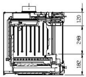
text_image
120 248 182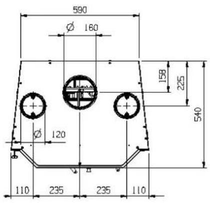
text_image
590 Ø 160 Ø 120 158 225 540 110 235 235 110INSERTO 70 VENTILATO PRISMATICO

text_image
690 550
text_image
225 94 331 125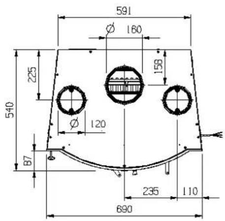
text_image
591 Ø 160 225 158 540 Ø 120 B7 235 110 690INSERTO 70 VENTILATO TONDO
This declaration of performance is issued under the manufacturer's sole responsibility referred to in point 4.
CE MARKING INFORMATION
DECLARATION OF CONFORMITY
According to the Directive 89/106/EEC (Construction Products), the CE Regulation No. 1935/2004 (Materials and Articles intended to come into contact with foodstuffs), the Directive 2006/95 CE (Low Voltage), the Directive 2004/108 CE (EMC).

DÉCLARATION DE CONFORMITÉ
Fireplaces by solid fuel
Space heating in buildings
The following harmonised standards or technical specifications (designations) which comply with good engineering practice in safety matters in force within the EEC have been applied:
Standards or other normative documents
Initial Type Tests Report
Prüfbericht
Rapport d'essai
RRF-2903569
EN 13229
EN 60335-2-102
EN 50366
EN55014-1
EN 55014-2
EN 61000-3-2
EN 61000-3-3
CE Marking information
As the manufacturer's authorised representative established within EEC, we declare under out sole responsibility that the equipment follows the provisions of the Directives stated above.
This declaration of performance is issued under the manufacturer's sole responsibility referred to in point 4.
CE MARKING INFORMATION
DECLARATION OF CONFORMITY
According to the Directive 89/106/EEC (Construction Products), the CE Regulation No. 1935/2004 (Materials and Articles intended to come into contact with foodstuffs), the Directive 2006/95 CE (Low Voltage), the Directive 2004/108 CE (EMC).

DÉCLARATION DE CONFORMITÉ
The following harmonised standards or technical specifications (designations) which comply with good engineering practice in safety matters in force within the EEC have been applied:
CE Marking information
As the manufacturer's authorised representative established within EEC, we declare under out sole responsibility that the equipment follows the provisions of the Directives stated above.
Data and models are not binding: the company reserves the right to perform modifications and improvements without notice.