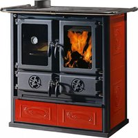
ThermoNicoletta Forno - Pan La Nordica - Free user manual and instructions
Find the device manual for free ThermoNicoletta Forno La Nordica in PDF.
Frequently Asked Questions - ThermoNicoletta Forno La Nordica
Download the instructions for your Pan in PDF format for free! Find your manual ThermoNicoletta Forno - La Nordica and take your electronic device back in hand. On this page are published all the documents necessary for the use of your device. ThermoNicoletta Forno by La Nordica.
USER MANUAL ThermoNicoletta Forno La Nordica
SAFETY REGULATIONS ON THE APPLIANCES
To meet safety regulations, it is compulsory to install and use our products carefully following the instructions contained in this manual.
DECLARATION OF CONFORMITY OF THE MANUFACTURER
Object: Absence of asbestos and cadmium We declare that the materials used for the assembly of all our appliances are without asbestos parts or asbestos derivates and that in the material used for welding, cadmium is not present, as prescribed in relevant norm. Object: CE n. 1935/2004 regulation. We declare that in all products we produce, the materials which will get in touch with food are suitable for alimentary use, according to the a.m. CE regulation.
Denition in accordance with EN 13240 Constructive system Global thermal power in kW Nominal thermal power in kW Power given back to water in kW Power given back to the room in kW Hourly wood consumption in kg / h (wood with 20% humidity) Efciency in % CO measured at 13% oxygen in % Smoke outlet diameter in mm Chimney height - dimension in mm (#) Fluid contents of the exchanger in L (litres) Chimney draught in Pa (mm H
Boiler connections (Ø) Automatic discharge pipe diameter (Ø) Outer air inlet Ø in mm (minimum surface cm
Exhaust gas emission in g/s – wood Exhaust gas temperature in °C - wood Optimal working temperature in °C Max. working pressure in bar Hearth opening size in mm (W x H) Hearth size in mm (W x H x D) Oven size in mm (W x H x D) Type of grill Movable - at Height in mm Width in mm Depth in mm Weight in Kg Fire prevention safety distances Chapter Fire prevention safety heatable m
(#) 200 mm diameter can be used with ue of no less than 6 m. (# #) For those buildings in which the thermal insulation does not correspond to the instructions on heat protection, the heating volume of the product is: favourable type of building (30 Kcal/h x m
); less favourable type of building (40 Kcal/h x m
); unfavourable type of building (50 Kcal/h x m
With thermal insulation in accordance with the regulations regarding energy saving, the heated volume is greater. With temporary heating, in the event of interruptions which last more than 8 hours, the heating capacity is reduced by about 25%. IMPORTANT: The power of the connected heating system must be proportional to the power transferred to the water by the thermoproduct; a charge which is too low does not allow regular oven operation, while a charge which is too high prevents adequate radiator heating.
2. GENERAL PRECAUTIONS
La NORDICA S.p.A. responsibility is limited to the supply of the appliance. The installation must be carried out scrupulously according to the instructions provided in this manual and the rules of the profession. Installation must only be carried out by a qualied technician who works on behalf of companies suitable to assume the entire responsibility of the system as a whole. La NORDICA S.p.A. declines any responsibility for the product that has been modied without written authorisation as well as for the use of non-original spare parts. NO MODIFICATIONS CAN BE CARRIED OUT TO THE APPLIANCE. La NORDICA S.p.A. cannot be held responsible for lack of respect for such precautions. It is OBLIGATORY to respect the National and European rules, local regulations concerning building matter and also reproof rules. TermoROSSELLA Plus - DSA TermoROSSELLA Plus Forno - DSA TermoNICOLETTA - DSA TermoNICOLETTA Forno - DSA
Installation of the product and auxiliary equipment in relation to the heating system must comply with all current Standards and Regulations and to those envisioned by the law. The installation and the relating to the connections of the system, the commissioning and the check of the correct functioning must be carried out in compliance with the regulations in force by authorised professional personnel with the requisites required by the law, being national, regional, provincial or town council present in the country within which the appliance is installed, besides these present instructions. Installation must be carried out by authorised personnel who must provide the buyer with a system declaration of conformity and will assume full responsibility for nal installation and as a consequence the correct functioning of the installed product. Before installing the appliance, carry out the following checks:
- Make sure that the oor can support the weight of the appliance, and if it is made of ammable material, provide suitable insulation (DIMENSIONS ACCORDING TO REGIONAL REGULATIONS). With a ammable oor the appliance must be installed on a 12 cm thick stone or concrete slab.
- Make sure that there is adequate ventilation in the room where the appliance is to be installed, with particular attention to windows and doors with tight closing (seal ropes).
- Do not install the appliance in rooms containing collective ventilation ducts, hoods with or without extractor, type B gas appliances, heat pumps, or other appliances that, operating at the same time, can put the room in depression (ref. UNI 10683 standard)
- Make sure that the ue and the pipes to which the appliance will be connected are suitable for its operation. It is not allowed the connection of various appliances to the same chimney.
- The diameter of the opening for connection to the chimney must at least correspond to the diameter of the ue gas pipe. The opening must be equipped with a wall connection for the insertion of the exhaust pipe and a rosette.
- The installation must be appropriate and has to allow the cleaning and maintenance of the product and the ue. Before installation, accurately wash the pipes of the system in order to remove any residuals that could compromise the correct functioning of the appliance. IMPORTANT: a) It would be appropriate to install an automatic or manual air valve to allow the air outlet from the plumbing system; b) In case of water leaking, close the water supply and promptly warn the after sales technical service; c) The system working pressure must periodically be checked. d) If not using the boiler for a long period of time, it is recommended that the after sales technical service is contacted to carry out at least the following operations:
- close the water taps of both the thermal system and the domestic hot water system;
- empty the thermal system and the domestic hot water system if there is risk of freezing. The DSA thermo appliances, can be installed in both an OPEN expansion Tank system (see chapter 3.1) and a CLOSED expansion Tank system (see chapter 3.2). La NORDICA S.p.A. declines all responsibility for damage to things and/or persons caused by the system. In addition, it is not responsible for any product modied without authorisation and even less for the use of non original spare parts. Your regular local chimney sweep must be informed about the installation of the appliance so that he can check the correct connection to the chimney. 3.1. OPEN expansion Tank system It is COMPULSORY that the OPEN expansion Tank system is provided with: 1. OPEN EXPANSION Tank: which has a capacity of 10% of total water content of thermo-product and of the installation. This is installed at the highest point of the system, at least 2 m over the radiator that is at the highest level. 2. SAFETY PIPE : that connects through the shortest way, without descending or siphoning parts, the delivery of thermo-product to the upper side of open expansion tank. ATTENTION: The inside diameter of the supply pipe which connects the thermoproduct with the open expansion vessel must be equal to the internal diameter of the supply junction present in the thermoproduct. The above mentioned connection pipe must be without siphoning parts. 3. LOAD PIPE : which connects the bottom of open expansion tank with the return pipe of installation. The minimum diameter must be ¾” gas. All those parts must no have for any reason meditate intercept bodies that could accidentally exclude them and must be placed in rooms which are protected from frost. On the contrary, if they freeze, the boiler body could break or even explode. In case of frost placing it will be right to add a proper percentage of antifreeze liquid to the water of installation in order to delete the whole problem. In no way there must be water circulation in the open expansion tank between the safety and loading pipe. This would cause the water oxygenation and the consequent corrosion of thermo-product and installation in a very short time. 4. THERMAL DISCHARGE VALVE which is a further positive safety that prevents the boiling even when electric energy is missing. It is made by a valve cover like a pressure safety valve which differs from it as it opens by reaching a pre-calibrated temperature (normally at 94 – 95°C) and unload hot water from the installation delivery. This will be replaced with as much cold water coming from the open expansion tank loading pipe of open tank by draining away the excessive heat. 5. SAFETY VALVE FROM 1,5 bar: maximum operation pressure allowed for the system is 1,5 bar (equal to 15 m of the water column). Higher pressures can cause deformation and breakage of the boiler body.
6. SAFETY DEVICES envisioned by Regulations in vigour.
7. CIRCULATION PUMP : . It would be better to install it on the return in order to avoid that it could disconnect itself at very high water temperatures but checking that it does not drive water in the open expansion tank otherwise it should cause a continuous water oxygenation with consequent, fast corrosion of boiler body. It must be not to avoid a forced circulation in the open expansion tank. Furthermore it must be electrically connected to a thermostat or a electronic control unit that can be purchased with the thermo- replace as OPTIONAL part.
8. ANTI-CONDENSATION MIXING VALVE – (see chapter 3.3)
ATTENTION: temperature safety sensors must be in place on the machine or at a distance no greater than 30 cm from the ow connectionTERMOROSSELLA PLUS DSA / FORNO DSA – TERMONICOLETTA DSA / FORNO DSA 18 7197100 - IT - EN - DE - FR of the thermo-product. Whenever the thermo products lack a device, those missing can be installed on the thermo product ow pipe, within a distance no greater than 1m from the thermo product. All those parts must no have for any reason meditate intercept bodies that could accidentally exclude them and must be placed in rooms which are protected from frost. On the contrary, if they freeze, the boiler body could break or even explode. ATTENTION: For no reason must the re be ignited before the system has been completely lled with water; doing this would lead to serious damage of the entire structure. The system must be lled by means of the loading pipe directly from the open tank in a way to prevent an excessive pressure of the water network deforming the body of the thermo heating stove. The system must be kept constantly full of water even during the periods when the use of the thermo-heating stove is not requested. During the winter, inactivity must be faced with the addition of antifreeze. 3.2. CLOSED expansion Tank system It is COMPULSORY that the CLOSED expansion Tank system is provided with: 1. A 3 bar SAFETY VALVE: maximum operation pressure allowed for the system is 3 bar (equal to 30 m of the water column). Higher pressures can cause deformation and breakage of the boiler body. ATTENTION: The inside diameter of the supply pipe which connects the thermoproduct with the security valve must be equal to the internal diameter of the supply junction present in the thermoproduct. The above mentioned connection pipe must be without siphoning parts.
4. CLOSED EXPANSION Tank can be installed on the thermo product return pipe. ATTENTION: The inside diameter of the return pipe which connects the thermoproduct with the closed expansion vessel must be equal to the internal diameter of the return junction present in the thermoproduct. The above mentioned connection pipe must be without siphoning parts.
ATTENTION: safety sensors must be in place on the machine according to that stated in chapter 3.1. All those parts must no have for any reason meditate intercept bodies that could accidentally exclude them and must be placed in rooms which are protected from frost. On the contrary, if they freeze, the boiler body could break or even explode. IT IS MANDATORY that the thermo products for domestic heating inserted in CLOSED Tank heating systems, must be internally equipped, with a cooling circuit, prepared by the unit manufacturer, which is activated by a thermal safety valve (see chapter 3.4) which does not require auxiliary power and can guarantee that the standard set temperature limit is not exceeded. Connection between the power supply unit and the valve must be free from interceptions. Cooling circuit upstream pressure must be at least 1,5 bar. 3.3. ANTI-CONDENSATION MIXING VALVE - (purchased as OPTIONAL part) The Anti-condensation mixing valve nds applications in solid fuel heat generators as it prevents cold water return in the exchanger Picture 1 at page 50. Routes 1 and 3 are always open and, along with the pump installed on the return (R), they guarantee water circulation inside the biomass boiler exchanger (CB). An elevated return temperature, allows efciency improvement, reduces formation of smoke condensation and prolongs the boiler life span. Valves on the market have different calibrations. La NORDICA advises use of model 55°c with 1” hydraulic connections. Once the valve calibration temperature is reached, route 2 opens and the boiler water goes to the system via the ow (M). IMPORTANT lack of installation of the device voids the heat exchanger warranty. 3.4. AUTOMATIC THERMAL DISCHARGE VALVE DSA (purchased as OPTIONAL part) Solid fuel thermo products must be installed with safety devices determined by laws in vigour. For this reason the thermo products is equipped with a heat discharge coil. The heat discharge coil must have one side connected to the water network (Picture 1 at page 50 / Chap. DIMENSIONS - A) and the other rot drainage network (C). When the safety temperature is reached, the automatic thermal discharge valve DSA, the bulb of which is to be connected to attachment B, enables the intake of cold water in the boiler coil, discharging the excess heat out of pipe C towards a conveniently installed drain. Cooling circuit upstream pressure must be at least 1,5 bar.
3.5. SYSTEM CONNECTION AND FILLING
Some examples, purely indicative of the installation, are reported at chapter INSTALLATION LAY-OUT, while the connections to the thermoproduct are reported at chapter DIMENSIONS . ATTENTION: The lling of the system must take place exclusively by the natural fall of the water from the open expansion tank through the feed pipe in order to avoid that a too high water system grid pressure could change or cause the explosion of boiler body. During this phase, open all the bleed valves of the radiators to prevent the formation of air sacks, checking the outlet of water to avoid unpleasant oodings. The watertight test of the installation is performed with the pressure of expansion tank open. The installation must always be full of water even when the thermo-product is not used. During winter season the non use has to be faced by adding antifreeze substances.TERMOROSSELLA PLUS DSA / FORNO DSA – TERMONICOLETTA DSA / FORNO DSA 7197100 - IT - EN - DE - FR 19
When installing the product, the following safety measures must be observed: a) In order to ensure sufcient thermal insulation, respect the minimum safety distance from objects or furnishing components ammable and sensitive to heat (furniture, wood sheathings, fabrics. etc.) and from materials with ammable structure (see Picture 5 at page 54 - A). All the minimum safety distances are shown on the product data plate and lower values must not be used. b) In front of the furnace door, in the radiation area there must be no ammable or heat-sensitive objects or material at a distance of less than 100 cm. This distance can be reduced to 40 cm where a rear-ventilated, heat-resistant protection device is installed in front of the whole component to protect. c) If the product is installed on a non totally refractory oor, one must foresee a reproof background. The oors made of inammable material, such as moquette, parquet or cork etc., must be replaced by a layer of no-inammable material, for instance ceramic, stone, glass or steel etc. (size according to regional law). In case the replacement of the oor is not possible, the appliance shall be placed on a minimum 12 cm thick slab made of stone or concrete. The base must extend at least 50 cm at the front and at least 30 cm at the sides, in addition to the opening of the loading door (see Picture 5 at page 54 - B). d) No ammable components (e.g. wall units) must be present above the product. The Product must always operate exclusively with the ash drawer inserted. The solid combustion residues (ash) must be collected in a sealed, re resistant container. The Product must never be on in the presence of gaseous emissions or vapours (for example glue for linoleum, petrol etc.). Never deposit ammable materials near the Product. During combustion, thermal energy is released which leads to considerable heating of the surfaces, doors, handles, controls, glass parts, the ue gas pipe and possibly the front part of the appliance. Avoid contact with these elements unless using suitable protective clothing or accessories (heat resistant gloves, control devices). Ensure children are aware of these dangers and keep them away from the furnace when it is on. When using the wrong fuel or one which is too damp, due to deposits present in the ue, a ue re is possible.
If there is a re in the ue connection : a) Close the loading door and the ash drawer door b) Close the comburent air registers c) Use carbon dioxide ( CO
powder ) extinguishers to put out the re d) Request the immediate intervention of the Fire Brigade DO NOT PUT OUT THE FIRE WITH WATER. When the ue stops burning, have it checked by a specialist to identify any cracks or permeable points.
Denition: thermo-product according to EN 13240. La Nordica thermoheating products are suitable for heating homes using a centralised heating system made up from radiators or heat convectors entirely or partially replacing the traditional gas or diesel oil boiler. The appliance works as an intermittent operating appliance. The appliance is composed of painted and galvanised sheet steel and cast iron. The replace is found inside the boiler, is built in 4 mm thick steel and is reinforced using welded nails. A swivelling, removable grid is found inside the replace. The water in the heating system circulates in the boiler, which absorbs the heat produced in the replace. The ceramic glass window (resistant up to 700°C) of the door provides a lovely view of the burning ames and prevents sparks and smoke from getting out. Room heating takes place: a) by radiation: the heat is radiated into the environment through the panoramic window and the hot external surfaces of the thermo- product; b) by conduction: radiators or heat convectors of the centralised system fed by hot water produced by the boiler (See chapter CALCULATION OF THE THERMAL POWER). The device is equipped with registers of primary and secondary air. 1A- PRIMARY air register (Picture 7 at page 55) With the primary air control is adjusted the passage of air through the ash drawer and the grate in the fuel direction. The primary air is necessary for the combustion process. The ash drawer must be regularly emptied, so that the ash does not obstruct the primary air entry. Through the primary air the re is also kept alive. During wood combustion, the primary air register must be almost completely closed during wood combustion, as otherwise the wood burns too quickly and the thermo-product may overheat. 2A - SECONDARY air register (Picture 7 at page 55) Over the door of the hearth there is the secondary air control.This regulator must be open (the lever must be moved to the right), especially for wood combustion, so that un-burnt carbon does not undergo a post-combustion. Through this register it is possible to adjust the power of the stove. Leaving it slightly open, according to the ue of the chimney, it is possible to keep the glass clean. Ash drawer for the collection of the ashes (Picture 9 at page 55). The adjustment of the registers necessary to reach the rated caloric yield is the following one: Fuel PRIMARY air SECONDARY air TERTIARY AIR Wood 1/5 OPEN OPEN PRE-ADJUSTEDTERMOROSSELLA PLUS DSA / FORNO DSA – TERMONICOLETTA DSA / FORNO DSA 20 7197100 - IT - EN - DE - FR
Essential requirements for correct appliance operation:
- the internal section must preferably be circular;
- the appliance must be thermally insulated and impermeable and built with suitable materials which are resistant to heat, combustion products and any condensation;
- there must be no narrowing and vertical passages with deviations must not be greater than 45°;
- if already used, it must be clean;
- the technical data from the instruction manual must be respected; If the ues are of a square or rectangular section, the internal edges must be rounded with a radius of not less than 20 mm. For the rectangular section, the maximum ratio between the sides must be ≤ 1.5. A section which is too small causes a reduction in draught. A minimum height of 4 m is advisable. The following materials are FORBIDDEN and compromise the good operation of the appliance: asbestos cement, galvanised steel, rough and porous internal surfaces. Picture 2 at page 52 shows some example solutions. The minimum section must be 4 dm
(for example 20x20 cm) for appliances whose pipe dimensions are less than 200 mm, or 6.25
(for example 25x25 cm) for appliances with a diameter of more than 200 mm. The draught created by your ue must be sufcient but not excessive. A section of the ue which is too large can present a volume which is too large to heat and therefore cause operating difculties for the appliance; to avoid this, it is necessary to intubate the appliance for its entire height. A section which is too small causes a reduction in draught. The ue must be at a suitably distance from ammable or combustible material using suitable insulation or an air space. It is FORBIDDEN to pass system piping or air ducts inside the ue. It is also forbidden to create moveable or xed openings on the ue itself, for the connection of further different appliances (See chapter CONNECTING A FIREPLACE OR OPEN HEARTH TO THE FLUE). 6.1. CHIMNEY POT The ue draught depends on the suitability of the chimney pot. It is therefore essential that, if built in a handcrafted way, the exit section is more than twice the internal section of the ue (Picture 3 at page 52) . As it must always go past the ridge of the roof, the chimney pot must ensure exhaust even in the presence of wind (Picture 4 at page 53). The chimney pot must meet the following requirements:
- Have an internal section equivalent to that of the chimney.
- Have a useful exit section of double the internal section of the ue.
- Be built so as to prevent rain, snow or any foreign body entering the ue.
- Be easy to inspect, for any maintenance and cleaning operations.
6.2. CONNECTION TO THE CHIMNEY
Products with automatic door closing (type 1) must operate, for safety reasons, with the furnace door closed (except during the fuel loading or ash removal phases). Products with non-automatic door closing (type 2) must be connected to their own ue. Operation with doors open is only allowed when supervised. The connection pipe to the ue must be as short as possible, straight horizontal and positioned slightly in ascent, and watertight. Connection must be carried out with stable and robust pipes,comply with all current Standards and Regulations and to those envisioned by the law, and be hermetically secured to the ue. The internal diameter of the connection pipe must correspond to the external diameter of the cooker ue gas exhaust stub pipe (DIN 1298). ATTENTION: as far as concern the realisation of the ue connection and ammable materials please follow the requirements provided by UNI 10683 standard. The ue must be properly spaced from any ammable materials or fuels through a proper insulation or an air cavity. For a better working of the appliance, it is suggested to have a ue draught of 17 - 20 Pascal (= 1,7 - 2,0 mm of column of water). The measurement has always to be carried out with hot device (rated thermal performance). When the depression exceeds 20 Pa (=2,0 mm of column of water), it is necessary to reduce the same by installing an additional draught regulator (buttery valve) on the exhaust pipe or in the chimney, according to the regulations in force. For correct appliance operation, it is essential that sufcient air for combustion is introduced into the place of installation (see paragraph AIR FLOW IN THE PLACE OF INSTALLATION DURING COMBUSTION). 6.3. CONNECTING A FIREPLACE OR OPEN HEARTH TO THE FLUE The ue gas channel is the stretch of piping which connects the thermo-product to the ue. In the connection, these simple but extremely important principles must be respected:
- under no circumstances use a ue gas channel with a diameter less than that of the exhaust clamp with which the thermo-product is equipped;
- each metre of the horizontal stretch of the ue gas channel causes a slight loss of head which must be compensated if necessary by elevating the ue;
- the horizontal stretch must never exceed 2 metres (UNI 10683);
- each bend of the ue gas channel slightly reduces the ue draught which must be compensated if necessary by elevating it suitably;
- The UNI 10683 – ITALY regulation requires that under no circumstances must there be more than 2 bends or variations in direction including the intake into the ue. If the user wishes to use the ue as a replace or open hearth, it is necessary to seal the hood below the entrance point of the ue gas channel pos. A Picture 6 at page 54. If the ue is then too big (e.g. 30x40cm or 40x50cm), it is necessary to intubate it with a stainless steel tube with a diameter of at least 200mm, pos. B, taking care to close the remaining spaces between the pipe and the ue immediately under the chimney pot pos. C.TERMOROSSELLA PLUS DSA / FORNO DSA – TERMONICOLETTA DSA / FORNO DSA 7197100 - IT - EN - DE - FR 21
8. ALLOWED / NOT ALLOWED FUELS
Allowed fuels are logs. Use exclusively dry logs (max. content of water 20%). Maximum 3 logs should be loaded. The pieces of wood should have a length of ca. 20-30 cm and a maximum circumference of 30-35 cm. Compressed not worked-out wood briquettes must be used carefully to avoid overheating that may damage the device, since these have a very high caloric value. The wood used as fuel must have a humidity content lower than the 20% and must be stored in a dry place. Humid wood tends to burn less easily, since it is necessary a greater quantity of energy to let the existing water evaporate. Moreover, humid content involves the disadvantage that, when temperature decreases, the water condensates earlier in the hearth and therefore in the stack causing a remarkable deposit of soot with following possible risk of re of the same. Fresh wood contains about 60% of H
O, therefore it is not suitable to be burnt. It is necessary to place this wood in a dry and ventilated place (for example under a roong) for at least two years before using it. Besides others, it is not possible to burn: carbon, cuttings, waste of bark and panels, humid wood or wood treated with paints, plastic materials; in this case, the warranty on the device becomes void. Paper and cardboard must be used only to light the re. The combustion of waste is FORBIDDEN and would even damage the appliance and the ue, causing health damages and claims by the neighborhood owing to the bad smell. The wood is not a fuel which allows a continuous operation of the appliance, as consequence the heating all over the night is not possible. Variety kg/mc kWh/kg moistness 20% Beech 750 4,0 Oak 900 4,2 Elm 640 4,1 Poplar 470 4,1 Larch* 660 4,4 Spruce* 450 4,5 Scots pine * 550 4,4
- RESINOUS WOOD NOT SUITABLE FOR THE BURNING ATTENTION : the continuous and protracted use of aromatic wood (eucalyptus, myrtle etc.) quickly damages the cast iron parts (cleavage) of the product.
7. AIR FLOW IN THE PLACE OF INSTALLATION DURING COMBUSTION
As the thermo-product draw their combustion air from the place of installation, it is MANDATORY that in the place itself, a sufcient quantity of air is introduced. If windows and doors are airtight (e.g. built according to energy saving criteria), it is possible that the fresh air intake is no longer guaranteed and this jeopardises the draught of the appliance and your health and safety. It is therefore necessary to guarantee a supply of fresh air through an external air inlet placed near the appliance or by placing piping for combustion air which leads outside or to a nearby airy place, with the exception of the boiler room or garage (FORBIDDEN). IMPORTANT: For a better comfort and corresponding oxygenation of environment, the stove / insert combustion air can be directly withdrawn at the outside. In order to do that, the stove can be connected to the external air socket by an junction (see Picture 9 at page 55 Chap. DIMENSIONS). The connection pipe must be smooth with a minimum diameter of 120 mm. It must have a maximum length of 4 m and have no more than three bends. If it is directly connected to the outside, it must be equipped with a suitable windbreak. The intake of air for combustion in the place of installation must not be obstructed during operation of the thermo-product. It is absolutely essential that in environments in which thermo-products are operated with a natural chimney draught, as much air as is necessary for combustion is introduced, i.e. up to 25 m³/hour. The natural recirculation of air must be guaranteed by some xed openings to the outside. Their size is established by regulations regarding the subject. Ask for information from a chimneys weep. The openings must be protected with grills and must never be blocked up. An extractor hood (suction) installed in the same room or in a neighbouring one causes a depression in the environment. This causes the leakage of burnt gas (dense smoke, smell); it is therefore necessary to ensure a greater ow of fresh air. The depression of an extractor hood can, in the worst case scenario, transform the ue of the thermo-product into an external air inlet, re sucking the ue gases into the environment with very serious consequences for persons.TERMOROSSELLA PLUS DSA / FORNO DSA – TERMONICOLETTA DSA / FORNO DSA 22 7197100 - IT - EN - DE - FR
ATTENTION: never light for any reason if the installation is not completely full of water in order to avoid a serious damage of the whole structure. IABSOLUTELY DO NOT LIGHT THE FIRE IN THE THERMO-FIREPLACE IN THE TOTAL OR PARTIAL ABSENCE OF WATER (NOT EVEN FOR CHECKING), AS IT COULD BE IRREMEDIABLY RUINED. IN SUCH CASE THE WARRANTY ON THE APPLIANCE IS VOIDED. WARNING: After the rst ignition you can smell bad odours (owing to the drying of the glue used in the garnitures or of the paint) which disappear after a brief using of the appliance. It must be ensured, in any case, a good ventilation of the environment. Upon the rst ignition we suggest loading a reduced quantity of fuel and slightly increasing the caloric value of the equipment To perform a correct rst lighting of the products treated with paints for high temperature, it is necessary to know the following information:
- the construction materials of the involved products are not homogeneous, in fact there are simultaneously parts in cast iron, steel, refractory material and majolica;
- the temperature to which the body of the product is subject is not homogeneous: from area to area, variable temperatures within the range of 300°C - 500°C are detected;
- during its life, the product is subject to alternated lighting and extinguishing cycles in the same day, as well as to cycles of intense use or of absolute standstill when season changes;
- the new appliance, before being considered seasoned has to be subject to many start cycles to allow all materials and paints to complete the various elastic stresses;
- in detail, initially it is possible to remark the emission of smells typical of metals subject to great thermal stress, as well as of wet paint. This paint, although during the manufacture it is backed at 250 °C for some hours, must exceed many times and for a given period of time the temperature of 350 °C before becoming completely embedded in the metallic surfaces. Therefore, it is extremely relevant to take these easy steps during the lighting:
1. Make sure that a strong air change is assured in the room where the appliance is installed.
2. During the rst starts, do not load excessively the combustion chamber (about half the quantity indicated in the instructions manual) and keep the product continuously ON for at least 6-10 hours with the registers less open than the value indicated in the instructions manual.
3. Repeat this operation for at least 4-5 or more times, according to your possibilities.
4. Then load more and more fuel (following in any case the provisions contained in the installation booklet concerning maximum load) and, if possible, keep the lighting periods long avoiding, at least in this initial phase, short ON/OFF cycles. 5. During the rst starts, no object should be leaned on the appliance and in detail on enameled surfaces. Enameled surfaces must not be touched during heating. 6. Once the «break-in» has been completed, it is possible to use the product as the motor of a car, avoiding abrupt heating with excessive loads. To light the re, it is suggested to use small wood pieces together with paper or other traded lighting means. It is FORBIDDEN to use any liquid substance as for ex. alcohol, gasoline, oil and similar. ATTENTION: during the rst lightings there could be a solid smokes condensation with a small escape of water from the thermo- replace: this event will expire in a very short time but if it persists it will be necessary to check the chimney draught. The openings for air (primary and secondary) must be opened together (you must open the eventual Ignition control, and buttery valve placed on the pipe of smokes exhaust). When the wood starts burning, you may load other fuels and adjust the air for combustion according to the instructions on paragraph DESCRIPTION. Please always be present during this phase. Never overload the appliance (see the technical table - max quantity of fuel that can be loaded / hourly consumption). Too much fuel and too much air for combustion can cause overheating and therefore damage the appliance. The warranty does not cover the damages due to overheating of the equipment. Never switch on the device when there are combustible gases in the room. 9.1. LOW EMISSION re lighting Smokeless combustion is a way of lighting a re able to signicantly reduce the emission of harmful substances. The wood burns gradually from the top downwards, so combustion is slower and more controlled. Burnt gases pass through the high temperatures of the ame and therefore burn almost completely. Place the logs in the hearth a certain distance apart as shown in the Picture 8 at page 55. Arrange the largest at the bottom and the smallest at the top, or vertically in the case of tall narrow combustion chambers. Place the re starter module on top of the pile, arranging the rst logs in the module at right angles to the pile of wood. Fire STARTER MODULE. This re starter module replaces a paper or cardboard starter. Prepare four logs, 20 cm long with a cross section of 3 cm by 3 cmPicture 8 at page 55. Cross the four logs and place them on top of the pile of wood at right angles, with the re lighter (wax impregnated wood bre for example) in the middle. The re can be lit with a match. If you want, you can use thinner pieces of wood. In this case, you will need a larger quantity. Keep the ue gas exhaust valve and combustion air regulator open. After lighting the re, leave the combustion air regulator open in the position shown: FUEL Primary AIR Aria SECONDARIA Wood CLOSED 1/2 OPEN IMPORTANT:
- do not add further wood between one complete load and the next;
- do not suffocate the re by closing the air intakes;
- regular cleaning by a chimney sweep reduces ne particle emissions.
After having positioned the registers correctly, insert the indicated hourly wood load avoiding overloads that cause anomalous stresses and deformations. You should always use the product with the door closed in order to avoid damages due to overheating (forge effect). The inobservance of this rule makes the warranty expire. For safety reasons the door of the appliances with constructive system 1, must be opened only for the loading of the fuel or for removing the ashes, while during the operation and the rest, the door of the hearth must remain closed. The appliances with constructive system 2 must be connected to their own ue. The operating with open door is allowed under supervision. IMPORTANT: For safety reasons the door of the hearth can be opened only for the loading of the fuel. The hearth door must always remain closed during operation or rest. With the controls positioned on the front of the appliance it is possible to adjust the heat emission of the hearth. They have to be opened according to the caloric need. The best combustion (with minimum emissions) is reached when, by loading the wood, most part of the air for combustion ows through the secondary air register. Never overload the appliance (see the hourly wood load in the table here below). Too much fuel and too much air for the combustion may cause overheating and then damage the stove. You should always use the appliance with the door closed in order to avoid damages due to overheating (forge effect). The inobservance of this rule makes the warranty expire. The adjustment of the registers necessary to reach the rated caloric yield with a depression at the stack of 17-20 Pa 1,7-2 mm of column of water) is the following one: see chapter TECHNICAL DESCRIPTION. The appliance works as an intermittent operating appliance. In the event that the water temperature exceeds the tripping temperature of the safety devices, immediately suspend the feeding of wood, and make sure that the water temperature and the ame decrease, eliminating the causes of the overheating (if necessary by closing the air register). If the water system is connected in the thermo-replace, the hot water tap can be opened to speed up the cooling of the appliance. Besides the adjustment of the air for the combustion, the intensity of the combustion and consequently the thermal performance of the device is inuenced by the stack. A good draught of the stack requires a stricter adjustment of air for combustion, while a poor draught requires a more precise adjustment of air for combustion. To verify the good combustion, check whether the smoke coming out from the stack is transparent. If it is white, it means that the device is not properly adjusted or the wood is too wet; if instead the smoke is gray or black, it signals that the combustion is not complete (it is necessary a greater quantity of secondary air). WARNING: When fuel is added onto the embers in the absence of a ame, a considerable amount of fumes may develop. Should this happen, an explosive mixture of gas and air may form, and in extreme cases an explosion may occur. For safety reasons it is advisable to perform a new lighting procedure with the use of small strips. 10.1. USE OF THE OVEN (If present) Thanks to the air ow for the combustion, the temperature of the oven may become remarkably affected. A sufcient ue of the chimney and of the channels, well cleaned for the ow of burning smokes around the oven are fundamental for a good cooking result. The oven pan may be located on different plans. Thick cakes and big roasts must be introduced in the lowest level. Flat cakes and biscuits must reach the medium level. The upper level may be used to heat or grill.
10.2. ELECTRICAL POWER SUPPLY FAILURE
In the event of an unexpected electrical power supply failure during normal system operation, it will be necessary to carry out these simple manoeuvres to prevent the water in the boiler starting to boil as a consequence of the lack of pump operation. 1. Raise the moveable furnace grill (if present ) to the highest level in order to reduce the exchange surface exposed to the heat of the ame.
2. Close the primary and secondary air registers in addition to turning the thermostat to 0 ( if present).
3. Open the oven door (if present) in order to favour the elimination of the internal heat.
4. Open the ue gas register ; in this way, it will deviate the residual heat still produced towards the chimney.
10.3. OPERATION IN TRANSITION PERIODS
During transition periods when the external temperatures are higher, if there is a sudden increase of temperature it can happen that the combustion gases inside the ue cannot be completely sucked up. The exhaust gases do not come out completely (intense smell of gas). In this case, shake the grating more frequently and increase the air for the combustion. Then, load a reduced quantity of fuel in order to permit a rapid burning (growing up of the ames) and the stabilization of the draught. Then, check that all openings for the cleaning and the connections to the stack are air-tigh. In case of doubt, do not operate the product. ATTENTION: never light for any reason if the installation is not completely full of water in order to avoid a serious damage of the whole structure. The installation must always be full of water even when the thermo-replace is not used. A possible no use during winter season must be faced by adding antifreeze substances. 10.4. SUMMER USE The system must be completely lled with water. The absence of water in the system would lead to serious damage of the entire structure. ATTENTION: For no reason must the re be ignited before the system has been completely lled with water; doing this would lead to serious damage of the entire structure.TERMOROSSELLA PLUS DSA / FORNO DSA – TERMONICOLETTA DSA / FORNO DSA 24 7197100 - IT - EN - DE - FR In order to prevent water boiling, the circulation pump must be always in function in order to drain on the radiators, or on the puffer, or on any other thermal absorption structure the heat given from the boiler to the water. If the pump does not circulate or for any reason the water temperature exceeds 95°C, acts the DSA valve discharging heat in the throughway water. It is recommended to supervise the water temperature in the thermoproduct during summer use to avoid recurrent interventions of the DSA valve which may jeopardize its good operation.
After cleaning the hearth, chimney and hood, totally eliminating the ash and other eventual residues, close all the doors of the hearth and the relevant registers; in case you disconnect the appliance from the chimney you must close its openings in order to let work others possible appliances connected to the same ue. We suggest performing the cleaning operation of the ue at least once per year; verifying in the meantime the actual status of the rope seals, which cannot ensure the good operation of the equipment if they are not in good condition and are not making a good seal! In this case the seals must be replaced. In presence of dampness in the room where the stove has been placed, we advise you to put absorbent salts into the hearth. If you want to keep for long the aesthetic look of the cooker it is important to protect its internal walls in row cast iron with neutral Vaseline. Check the water level in the expansion tank and remove any air from the system by bleeding the radiators; also check to make sure that the plumbing and electrical accessories (control unit, circulator) are working properly. ATTENTION: For no reason must the re be ignited before the system has been completely lled with water; doing this would lead to serious damage of the entire structure. The installation must always be full of water even when the thermo-replace is not used.
12. MAINTENANCE AND CARE
Check the external air intake, by cleaning it, at least once a year. The stack must be regularly swept by the chimney sweeper. Let your chimney sweeper in charge of your area check the regular installation of the device, the connection to the stack and the aeration. IMPORTANT: The maintenance must be carried out only and exclusively with cold device . You should only use spare parts approved and supplied by La NORDICA. Please contact your specialized retailer if you require spare parts. YOU MUST NOT MAKE ANY CHANGES TO THE DEVICE!!! 12.1. MAJOLICAS La NORDICA has chosen majolica tiles, which are the result of high-quality artisan work. As they are completely carried out by hand, the majolica may present crackles, speckles, and shadings. These characteristics certify their precious origin. Enamel and majolica, due to their different coefcient of dilatation, produce microcrackles, which show their authentic feature. For the cleaning of the majolica we suggest you to use a soft and dry cloth; if you use a detergent or liquid, the latter might soak in and highlight the crackles permanently.
12.2. PRODUCTS MADE OF NATURAL STONE
Natural stone has to be cleaned with very thin abrasive paper or with an abrasive sponge. Do NOT use any cleanser or uid. 12.3. VARNISHED PRODUCTS After some years of product use a change in the varnished details colour is totally normal. This is due to the considerable temperature range the product is subject to whenever in use and to the varnish ageing of time passing by. ATTENTION: before any possible application of the new varnish, do clean and remove all the traces from the surface which has to be varnished. 12.4. ENAMELLED PRODUCTS For the cleaning of enamelled surfaces use soap water or not aggressive and not chemically abrasive detergents. After the cleaning do NOT let soapy water or any cleanser dry but remove them immediately. 12.5. CHROMIUM-COMPONENTS If the components become bluish due to overheating, this can be solved with a suitable product for cleaning. DO NOT use abrasives or solvents. 12.6. CAST IRON TOP and the HOT PLATES The cast iron top (cookers) and the hot plates (cookers - stoves) should be periodically sanded with 150 grit sandpaper. NO enamelled surfaces. 12.7. GLASS CLEANING Thanks to a specic inlet of secondary air, the accumulation of dirty sediments on the glass-door is reduced with efcacy. Nevertheless this can never be avoided by using solid fuels ( particularly wet wood ) and it has not to be understood as a defect of the appliance. IMPORTANT: The cleaning of the sight glass must be carried out only and exclusively with cold device to avoid the explosion of the same. For the cleaning, it is possible to use specic products or a wet newspaper paper ball passed in the ash to rub it. Do not use cloths, abrasive or chemically aggressive products by cleaning the hearth glass. The correct lighting phase, the use of proper quantities and types of fuels, the correct position of the secondary air regulator, enough draught of the chimney-ue and the presence of combustion air are the essential elements for the optimal functioning of the appliance and for the cleaning of the glass. BREAK OF GLASSES: Given that the glass-ceramic glasses resist up to a heat shock of 750°C, they are not subject to thermal shocks. Their break can be caused only by mechanic shocks (bumps or violent closure of the door, etc.). Therefore, theirTERMOROSSELLA PLUS DSA / FORNO DSA – TERMONICOLETTA DSA / FORNO DSA 7197100 - IT - EN - DE - FR 25 replacement is not included in the warranty.
12.8. CLEANING OUT THE ASHES
All the devices are equipped with a hearth grating and an ash drawer for the collection of the ashes Picture 9 at page 55. It is suggested to empty periodically the ash drawer and to avoid it lls completely in order not to overheat the grating. Moreover, it is suggested to leave always 3-4 cm of ash in the hearth. CAUTION: The ashes removed from the hearth have to be stored in a container made of re-resistant material equipped with an air-tight cover. The container has to be placed on a re-resistant oor, far from ammable materials up to the switching off and complete cooling.
12.9. CLEANING THE FLUE
The correct lighting phase, the use of proper quantities and types of fuels, the correct position of the secondary air regulator, enough draught of the chimney-ue and the presence of combustion air are the essential elements for the optimal functioning of the appliance. The device should be completely cleaned at least once a year or every time it is needed (in case of bad working and low yield). An excessive deposit of soot can cause problems in the discharge of smokes and re in the ue. The cleaning must be carried out exclusively with cold equipment. This operation should be carried out by a chimney sweeper who can simultaneously perform an audit of the ue (checking of possible deposits).
12.10. MAINTENANCE ON THE WATER SYSTEM
Excessive incrustation deposits on the inner walls of the hearth considerably reduce the efciency of heat exchange; therefore, remove these deposits using a steel brush whenever necessary. Never use corrosive substances that can damage the thermo-replace and the boiler. With the system switched off, once a year carry out the following checks:
- Check the operation and efciency of the blowdown and safety valves. If they are defective, contact your authorised installer. IT IS STRICTLY FORBIDDEN TO REMOVE OR TAMPER WITH THE SAFETY DEVICES.
- Check the thermal insulation of the lling pipe and the safety pipe.
- Make sure that the system is lled and under pressure, checking the water level in the expansion tank; also check that it is working properly and check the efciency of the safety pipe.
13. CALCULATION OF THE THERMAL POWER
There is not an absolute rule for calculating the correct necessary power. This power is given according to the space to be heated, but it depends also largely on the insulation. On an average, the caloric value necessary for a properly insulated room is 30 kcal/h per m
(for an external temperature of 0°C). Given that 1 kW corresponds to 860 kcal/h, it is possible to adopt a value of 38 W/m
Let’s suppose one wishes to heat a room of 150 m
(10 x 6 x 2.5 m) in an insulated apartment. In this case, it is necessary to have 150 m
8. COMBUSTIBLES ADMIS / NON ADMIS
Our responsibility is limited to the supply of the appliance. Its system is realised precisely according to the provisions of the following instructions and the regulations of the profession, by qualied staff, which acts in the name of companies suitable to assume the entire responsibility of the system according to that stated in chapter INSTALLA TION REGULATIONS. The present planes are purely indicative, therefore they have not value as project. According to the laws, the present documentation is closely condential and reserved and it is forbidden the reproduction, the use and the communication to a third party. The diffusion not allowed from La NORDICA S.p.a. will be sanctioned from the laws.
Wall mounted gas boiler
/h at min. 1 bar ow pressure and sensor temp. 110°C Manual button ABS Connection size: G3/4 pipe thread ISO 228 Pulsante manuale: ABS Length of capillary tube: 1.3 m or 4 m APPLICATION The Thermostatic Valve VAST is designed for protection of biomass boilers and re stoves It prevents overheating of the boiler by discharging water from heat generator or condensing coil. The valve is used also to prevent back-burning in the fuel store by ooding the fuel in case of excessive temperature. INSTALLATION Installation of VAST valve on boiler with safety heat exchanger (diagram 1 at page 50). Before installation of the valve ush the system to make sure that there are no impurities which might deposit on the valve seat and cause malfunction. Remember to install a lter ahead of the valve. The sensor can be mounted in any position. Make sure the whole sensor is in contact with the controlled area. The arrow on the valve body shows direction of ow. When installing the valve, make sure it is positioned properly. Max torque for sensor pocket mounting is 30Nm. SERVICE It is recommended to check proper function of the valve once a year by qualied personnel. Functional check is carried out manually by depressing the red button that opens the ow on the valve. The nut fastening the red button must not be loosened as it will cause product malfunction. 14.1. Thermostatisch gesteuerte Ventil VAST TECHNISCHE PROTOKOLLE Technische Daten Werkstoffe Medien: Wasser Gehäuse und andere Metallteile: Geschmiedetes Messing Max. Betriebsdruck: 10 bar Feder: Edelstahl Medientemperatur: 5 bis 110°C Fühler: Messing Öffnungstemperatur: 95°C (fest) Kapillarrohr: Kupfer Hysterese: 6°C Tauchhülse: Messing Umgebungstemperatur: 0 bis 125°C O-Ringe und Dichtungen: EPDM, NBR Strömungsleistung: 2.4 m
Place the lateral tiles (A) in one side, starting from the bottom by hooking the holders (B) where the side supports (C) are. Go on with the other side of the stove. Place the upper ceramic covering (D), putting it on the rear side of the stove (E) and in front where the heating shelter (F) is. CAUTION: handle the tiles with great care as they could be damaged being very fragile.
EasyManual