TV Easyslide Twin S - Wall mount Goobay - Free user manual and instructions
Find the device manual for free TV Easyslide Twin S Goobay in PDF.

Frequently Asked Questions - TV Easyslide Twin S Goobay
User questions about TV Easyslide Twin S Goobay
0 question about this device. Answer the ones you know or ask your own.
Ask a new question about this device
Download the instructions for your Wall mount in PDF format for free! Find your manual TV Easyslide Twin S - Goobay and take your electronic device back in hand. On this page are published all the documents necessary for the use of your device. TV Easyslide Twin S by Goobay.
USER MANUAL TV Easyslide Twin S Goobay
text_image
goobay® VESA MOUNTING COMPANY UNITED STATES OF AMERICA| DE | BETRIEBSANLEITUNG |
| EN | USER'S MANUAL |
| FR | MODE D'EMPLOI |
| IT | ISTRUZIONI PER L'USO |
TV-Wandhalter TV wall mount TV Support mural Attaco a parete per TV
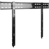
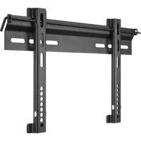
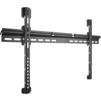
63479 Goobay TV EasySlide S
natural_image
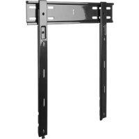
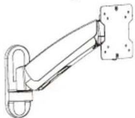
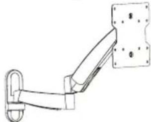
Technical line drawing of a mechanical arm or bracket assembly (no text or symbols)63480 Goobay TV EasySlide Twin S
natural_image
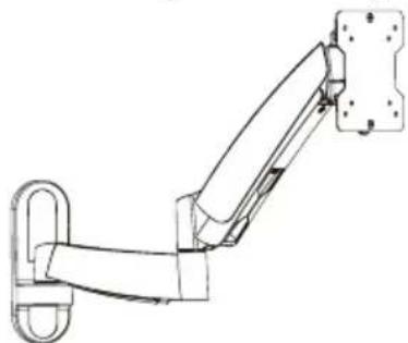
Technical line drawing of a mechanical arm or linkage assembly (no text or symbols)63481 Goobay TV EasySlide M
natural_image
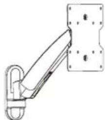
Technical line drawing of a mechanical arm with a wall-mounted panel (no text or symbols)63482 Goobay TV EasySlide Twin M
natural_image
Line drawing of a mechanical arm with attached mounting bracket (no text or symbols)
BETRIEBSANLEITUNG 2
USER'S MANUAL.... 20
MODE D'EMPLOI 38
ISTRUZIONI PER L'USO 56
BETRIEBSANLEITUNG
Inhalt
Schraubenschlüssel D
4.2.1 Vorbereitung
text_image
60mm (2.4") Ø 160mm tief. (Ø 3/8")natural_image
Technical line drawing of a mechanical joint or bracket assembly mounted on a brick wall (no text or symbols)7.
natural_image
Two icons: a screwdriver and a group of people holding a document (no text or symbols present)Schraubenschlüssel D
1 Safety Instructions 21
1.1 General Notes ...... 21
1.2 User Groups 22
1.3 Warning Levels....22
2 Description and Function....23
2.1 Scope of Delivery for Models 63479 and 63480......23
2.2 Scope of Delivery for Models 63481 and 63482......24
2.3 Required tools for all Models....25
3 Intended Use....25
3.1 Use restrictions....26
4 Installing....26
4.1 Preparing....26
4.2 Wall mounting....26
4.2.1 ...Preparing....27
4.2.2...Wall mounting....27
4.3 Mounting the flat screen 28
4.3.1 ...Flat screens with flat back....28
4.3.2...Flat screens with arched back 29
4.4 Attaching and fastening the flat screen....30
4.5 Adjusting the flat screen 31
4.5.1 ...Adjusting the swivel arm .... 31
4.5.2...Setting the VESA plate....32
4.5.3...Adjusting the flat screen....32
5 Maintenance, Care, Storage and Transport 33
6 Troubleshooting 33
7 Specifications....33
7.1 Specifications of Models 63479 and 63480....34
7.1 Specifications of Models 63479 and 63480....34
7.1 Specifications of Models 63479 and 63480....34
7.1 Specifications of Models 63479 and 63480....34
7.1 Specifications of Models 63479 and 63480....34
7.1 Specifications of Models 63479 and 63480....34
7.1 Specifications of Models 63479 and 63480....34
7.1 Specifications of Models 63479 and 63480....34
7.1 Specifications of Models 63479 and 63480....34
7.1 Specifications of Models 63479 and 63480....34
7.1 Specifications of Models 63479 and 63480....34
7.1 Specifications of Models 63479 and 63480....34
7.1 Specifications of Models 63479 and 63480....34
7.1 Specifications of Models 63479 and 63480 ......
7.1 Specifications of Models 63479 and 63480....34
7.1 Specifications of Models 63479 and 63480....34
7.1 Specifications of Models 63479 and 63480....34
7.1 Specifications of Models 63479 and 63480....34
8 Information for VESA standard....35
7.2 Specifications of Models 63481 and 63482....34
9 Disposal Instructions 35
1 Safety Instructions
1.1 General Notes
- Read the including product documentation completely and carefully before use. It is part of the product.
- Attend to the safety instructions in product documentation, on product and accessories, such as on the package.
- Use product, product parts and accessories only in perfect condition.
- Keep the product documentation for other potential users and for later requests.
- For questions, defects, mechanical damage, disturbances and other not remediable problems, consult your dealer.
Risk of life by suffocating
Children can suffocate by swallowed or inhaled parts and insulation materials.
Protect small parts and insulation material against unintentionally use.
Risk of injury by tripping and falling
Unfavorable placed or installed products and cable connections can injure persons.
Place, transport and install product, parts and accessories in a safe way.
When working with burdens, secure yourself and the working place, let a second person help you.
Let only a specialist do disassembly, maintenance and repair work.
Risk of injury by cutting
Children can cut themselves on packaging materials.
Protect packaging materials against unintentionally use.
Risk of material damage by improper product combination
Incompatible product combination does not fulfill required functions, can cause quality losses or material damage.
The specifications of all used products must match or be within the specified range.
Risk of injury by inappropriate ambient conditions
Extreme conditions can injure persons.
Attend to live cables or other lines lying behind plaster, and do not damage them!
Do not install the product to places with direct sunlight or bright light. This contributes to eye fatigue.
Risk of injury by moving product parts
Moving product parts can pinch or squeeze limbs.
Do not hold limbs between shear parts during use.
Mind the mobility of the product during use. This may move away from the wall or towards it and swivel sideways.
Risk of self-intervention and misuse

Self-interventions and misuse hide unpredictable risks and cause expiration of warranty.
Do not modify or alter either the product or the accessories!
Risk of material damage by inappropriate ambient conditions
Incorrect ambient conditions can damage things.
Avoid extreme conditions, such as extreme heat, coldness, humidity or direct exposure to the sun, as well as vibrations and mechanical pressure.
Keep enough space around product and to the whole system to ensure proper ventilation and mobility.
The included mounting material is only suitable for mounting on massive stone or concrete walls.
For other wall types use suitable mounting material.
Check the stability of the system periodically after installation.
1.2 User Groups
Caused to different risk levels and hazard potentials some working steps only may be done by trained specialists.
| Working step User Group | |
| Installing, Uninstalling, Aligning, Care, Storage, Transport, Disposal | Consumers and users with basical mechanical knowledge can do this work.>> Protect children and people with mental and motoral impairments from using the product! |
| Maintenance, Repairing | Trained specialists only>> special safety measures, knowledge and tools are necessary! |
Tab.15: User Groups
1.3 Warning Levels

Warnings against hazards that will result directly in serious injuries or death in case of non-observance.

Warnings against hazards that may result in serious injuries or death in case of nonobservance.

Warnings against hazards that may result in injuries in case of non-observance.

Warnings against hazards that may result in material damage in case of non-observance.
2 Description and Function
Your TV wall mount is used for mounting your flat screens to secure and vertical walls. All models listed are individually tiltable and swivelable and feature a cable management system.
Models 63479 and 63480 are limited to flat screen mounting with flat backs. Furthermore, these are designed for smaller screen sizes and weights than the models 63481 and 63482.
Models 63480 and 63482 have a double swivel arm and thus have a greater variability than the models 63479 and 63481.
Refer to the specifications for details of your model.
2.1 Scope of Delivery for Models 63479 and 63480
| Part Figure Symbol Amount | |||
| Wall mounting | |||
| TV wall mount with VESA plate and plastic covers | |||
| 63479 | 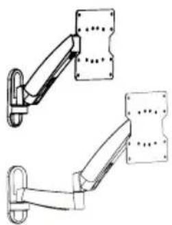 | A | 1 |
| or | |||
| 63480 | |||
| Wall screw 6.3x55 | 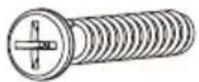 | W-A 3 | |
| Concrete anchor | 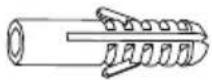 | W-B 3 | |
| Flat screen mounting | |||
| M4x14 M-A 4 | 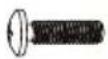 | ||
| M5x14 | 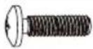 | M-B 4 | |
| Washer D5 | 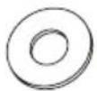 | M-C 4 | |
| Tools | |||
| Allen key 3 mm | 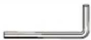 | B | 1 |


| Allen key6 mm | 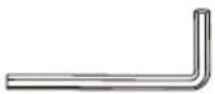 | C | 1 |
| Wrench |  | D | 1 |
Tab. 16: Scope of Delivery for Models 63479 and 63480
2.2 Scope of Delivery for Models 63481 and 63482
| Part Figure Symbol Amount | |||
| Wall mounting | |||
| TV wall mount with VESA plate and plastic covers | |||
| 63481 | 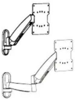 | A | 1 |
| or | |||
| 63482 | |||
| Wall screw 6.3x55 |  | W-A 3 | |
| Concrete anchor | 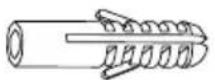 | W-B 3 | |
| Flat screen mounting | |||
| M4x14 M-A 4 | 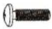 | ||
| M5x14 |  | M-B 4 | |
| M6x14 |  | M-C 4 | |
| M8x20 | 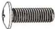 | M-D 4 | |
| Washer D5 | 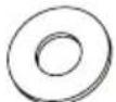 | M-E 4 | |
| Washer D8 | 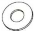 | M-F 4 | |
| TV Spacer | [67XZ] | M-G 8 | |
Tools
| Allen key3 mm | 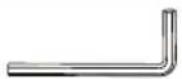 | B | 1 |
| Allen key6 mm | 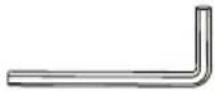 | C | 1 |
| Wrench | 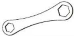 | D | 1 |
Tab.17: Scope of Delivery for Models 63481 and 63482
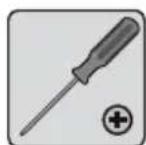
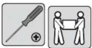
2.3 Required tools for all Models
| Tool Figure | |
| Line tester |  |
| Spirit level |  |
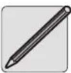
| Pencil |  |
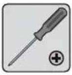
| Phillips screwdriver |  |
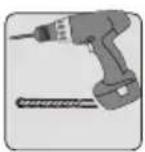
| Drilling mashine |  |
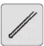
| Concrete drill 8x60mm |  |
| Second person | 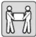 |
Tab.18: Required tools for all Models
3 Intended Use
This product is made for mounting flat screens with specific screen sizes, weights and mounting points, which are summarized in chapter "Technical data", on a vertical wall. Another use than described in chapter "Description and

Function" is not permitted. Neglegting and ignoring these regulations and safety instructions can cause serious accidents, personal injury and material damage. Also refer to chapter "Warranty and Liability".
3.1 Use restrictions
Only use in dry interior rooms.
4 Installing
4.1 Preparing
Checking the completeness and integrity
Check the packing content by comparing it to the scope of delivery regarding completeness and integrity.
Ensuring compatibility
| NOTICE | Risk of material damage by improper product combination |
| >> The specifications of all used products must match or be within the specified range. |
Tab. 19: Ensuring compatibility
4.2 Wall mounting
| CAUTION | Risk of injury due to inappropriate ambient conditions | |
| >> Check the wall structure before installing or choose a safe installation place.>> Attend to live cables or other lines lying behind plaster, and do not damage them! | ||
| >> Do not install the product to places with direct sunlight or bright light. This contributes to eye fatigue. | ||
| NOTICE | Risk of material damage by inappropriate ambient conditions | |
| >> Keep enough space around product and to the whole system to ensure proper ventilation and mobility. | ||
ab.20: Wall mounting
Tools for all Models
 |  |  |  |  |  |
additional tools for Models 63479 and 63480
Wrench D
4.2.1 Preparing
text_image
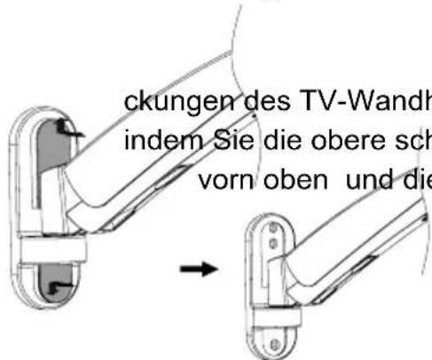
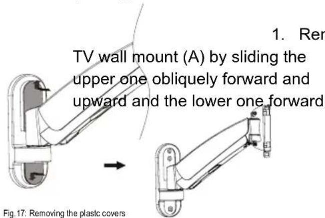
1. Ren TV wall mount (A) by sliding the upper one obliquely forward and upward and the lower one forward Fig.17: Removing the plastic covers- Remove the 2 plastic covers of the
and downward.
text_image
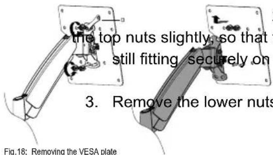
the top nuts slightly, so that still fitting securely on 3. Remove the lower nuts Fig.18: Removing the VESA plate-
Remove the VESA plate by loosening
-
Remove the lower nuts counterclock-
wise and completely.
4.2.2 Wall mounting
text_image
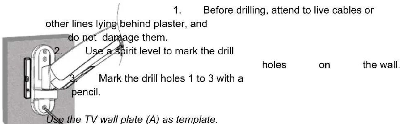
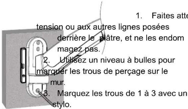
1. Before drilling, attend to live cables or other lines lying behind plaster, and do not damage them. 2. Use a spirit level to mark the drill 3. Mark the drill holes 1 to 3 with a pencil. holes on the wall. Use the TV wall plate (A) as template.Fig.19: Aligning and marking
text_image
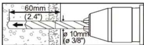
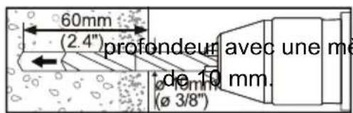
60mm (2.4") Ø 10mm (Ø 3/8")Fig.20: Drilling drill holes
- Drill the drill holes with a 10mm concrete drill 60mm deep.

- Plug a concrete anchor (W-B)
text_image
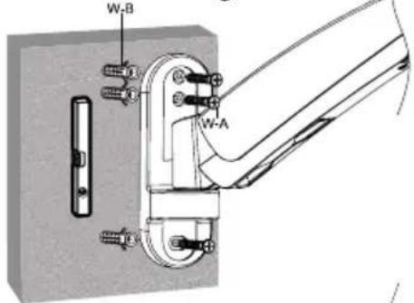
W-B W-AFig.21: Wall mounting
6.
in
each
drillin
Attach the TV wall mount (A) with the wall screws (W-A) so that the notch on the VESA plate is pointing upwards.
- Reattach the plastic covers to
natural_image
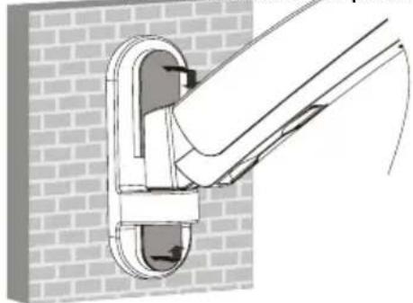
Technical line drawing of a pipe joint with a brick wall background (no text or symbols)Fig.22: Reattaching the plastic covers
the TV wall mount (A).
4.3 Mounting the flat screen

CAUTION
Risk of injury by tripping and falling
Place, transport and install product, parts and aceories in a safe way.

NOTICE
Risk of material damage by improper procedure
Only use moderate force when tightening the screws in order to avoid damaging threads.

NEVER set the screen on the front during installation!

Do not damage the flat screen by too long screws.
Tab.21: Mounting the flat screen
4.3.1 Flat screens with flat back
Tools for all Models

text_image
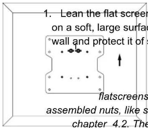
on a soft, large surfac wall and protect it of s flatscreens assembled nut, like sh 4.2. These parts keepFig.23: Aligning the VESA plate 4.3.1
1. Lean the flat screen vertically
on a soft, large surface or a
wall and protect it of scratches
and overturning.

Make sure that screw 1 sits on the
flatscreens top side with the pre-
assembled nut, like shown in chapter
4.2. These parts keep VESA plate
and flat screen while attaching them
to the wall plate.
text_image
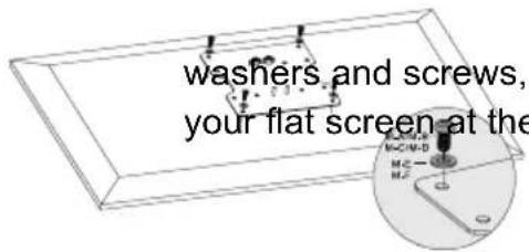
washers and screws, your flat screen at the2. Attach the VESA plate with the
washers and screws, fitting to your flat screen at the flat
screens back as
Fig.24: Attaching the VESA plate 4.3.1
4.3.2 Flat screens with arched back
Tools for all Models
Using flat screens with arched backs is only possible with models 63481 and 63482.
text_image
1. Lean the flat screen on a soft, large surfac wall and protect it of s flatscreens assembled nuts, like s chapter 4.2. TheFig.25: Aligning the VESA plate 4.3.2
and overturning.
Make sure that screws1 sit on the
plate and flat screen while attaching
them to the wall plate.

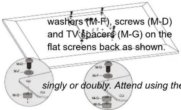
text_image
washers (M-F), screws (M-D) and TV spacers (M-G) on the flat screens back as shown. singly or doubly. Attend using theFig.26: Attaching the VESA plate 4.3.2
2. Attach the VESA plate with
The TV spacers (M-G) can be used
adequate
screw
leng
4.4 Attaching and fastening the flat screen
 | Risk of injury by tripping and falling>> Place, transport and install product, parts and aceories in a safe way.>> When working with burdens, secure yourself and the working place, let a second person help you. |  |
 | Risk of material damage by inappropriate ambient conditions>> Keep enough space around product and to the whole system to ensure proper ventilation and mobility. |  |
Tab.22: Attaching and fastening the flat screen
Tools for all Models
natural_image
Two icons: a screwdriver and two stylized human figures holding a document (no text or symbols)additional tools for Models 63479 and 63480
Wrench D
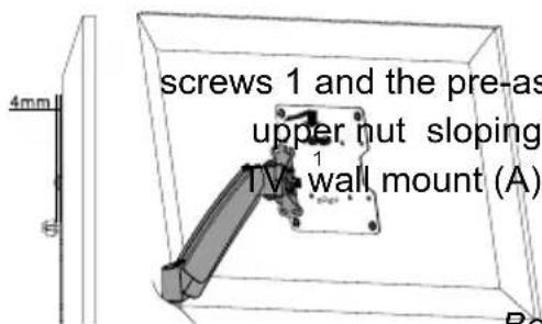
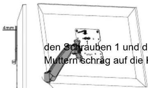
text_image
screws 1 and the pre-as upper nut sloping TV wall mount (A)1. Hang flat screen and VESA plate with
screws 1 and the pre-assembled
upper nut slopingly to the notch of the
TV wall mount (A) together with a
second
person.
Fig.27: Attaching the flat screen
Between the upper nuts and the threaded
stopper, a gap of about 4 mm is ideal.
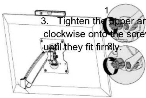
text_image
3. Tighten the upper an clockwise onto the screw until they fit firmly.- Set the flat screen vertically.
Fig.28: Fastening the flat screen
4.5 Adjusting the flat screen

CAUTION
Risk of injury by moving product parts
Do not hold limbs between shear parts during use.
Mind the mobility of the product during use. This may move away from the wall or towards it and swivel sideways.

NOTICE
Risk of material damage by inappropriate ambient conditions
Keep enough space around product and to the whole system to ensure proper ventilation and mobility.

Tab.23:Adjusting the flat screen
4.5.1 Adjusting the swivel arm
Tools
Allen key 6 mm
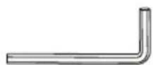
C
With the 6 mm Allen screw you can adjust the spring tension of the swivel arm. A heavy flat screen requires a tighter adjustment than a slight.
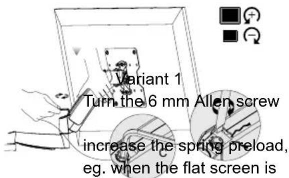
text_image
Variant 1 Turn the 6 mm Allen screw increase the spring preload, eg. when the flat screen is- Secure the swivel arm with one hand.
counterclockwise to (+)
Fig.29: Adjusting the swivel arm
constantly moving down itself.
Variant 2
Turn the 6 mm Allen screw clockwise to decrease the spring preload, eg. when the flat screen is constantly moving up itself.
4.5.2 Setting the VESA plate
Tools
Allen key
3 mm
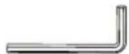
B
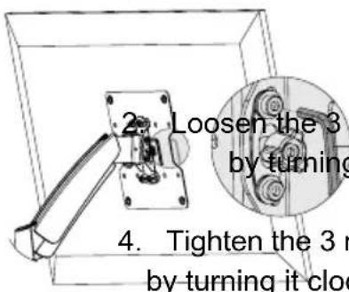
text_image
2. Loosen the 3 by turning 4. Tighten the 3 m by turning it cloc- Secure the swivel arm with
one hand.
3.
Adjust
the
t
Fig.30: Setting the VESA plate
4.5.3 Adjusting the flat screen
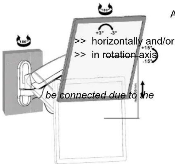
text_image
> horizontally and/or >> in rotation axis -15° be connected due to the +3° -3° -180° m±5mm AAlign the flat screen as needed
vertically
Power cords can subsequently
mobility
of the
wall
Fig.31: Adjusting the flat screen
4.6 Managing the cables

Risk of material damage by inappropriate ambient conditions
Keep enough space around product and to the whole system to ensure proper ventilation and mobility.

Tab.24: Managing the cables
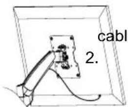
text_image
cable 2.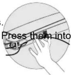
text_image
. Press them into- Connect sufficiently long
holder(s).
Fig.32: Managing the cables
Make sure leaving enough slack
around the cables, to ensure mobility
of the system.

End of installing. To remove, proceed in reversed order.
5 Maintenance, Care, Storage and Transport
• The product must be maintained only by professional workshops.
- Protect the angles from dirt and grease them regularly with light machine oil.
- Use a dry and soft cloth to clean your product. Be careful to avoid scratches. Use a slightly moist cloth for heavy stains. Look out for live cables! Do not use any cleaning supplies. This can cause burns to the materials. Avoid liquid entry to the device.
• Make sure no body parts will be pinched in the swivel device, when parts of the device are moved!
- Periodically check, if all attachments and screws are secured, and tighten them again when they are loosened. This may be caused e.g. by frequent movements. Do not overtighten screws.
- Avoid places with high temperatures, humidity, or places which can become wet, also during maintenance, care, storage, and transport.
- Keep the product away from children and store it at dry and dust-proof places!
- Drill holes are still visible after removing the product. After use for a longer time period, a spot may remain on the surface.
- Keep the original packing for transport and to avoid damages.
6 Troubleshooting
| Problem Help | |
| How to test wall quality? | Loads for home use are regulated in various European standards.>> Check wall thickness and material under plaster / wall paper.>> Ask a specialist. |
| Which drill holes must be drilled? | >> Read chapter 4.2. |
| The wall mount is hard to align. | >> Due the TV size the maximum swivel angle may be smaller than indicated. |
| The TV wall mount makes sounds | >> These result from the internal spring and are normal during moving.>> Occuring in resting position, read chapter 4.5.1. |
| Other questions >> Contact your dealer. | |
Tab.25: Troubleshooting
7 Specifications

7.1 Specifications of Models 63479 and 63480
| Physical size Specification Unit | ||
| TV Size 13-27 " / Inch | ||
| VESA 75x75 / 100x100 mm | ||
| Load max. 15 kg | ||
| Tilting angle +/-15 ° | ||
| Swivel angle of VESA plate | +/-90 ° | |
| Swivel angle per swivel arm | +/-90 ° | |
| Rotation angle of VESA plate | +/-2 | ° |
| Wall distance | 63479: 50-36063780: 55-580 | mm |
| Dimensions | 63479: 132 x 475 x 50-36063480: 132 x 475 x 55-580 | mm |
| Weight | 63479: 2.4063480: 2.95 | kg |
Tab.26: Specifications of Models 63479 and 63480
7.2 Specifications of Models 63481 and 63482
| Physical size Specification Unit | ||
| TV Size 17-42 “ / Inch | ||
| VESA | 100x100 / 200x100 / 200x200 | mm |
| Load max. 20 | kg | |
| Tilting angle +/-15 ° | ||
| Swivel angle of VESA plate | +/-90 ° | |
| Swivel angle per swivel arm | +/-90 ° | |
| Rotation angle of VESA plate | +/-3 | ° |
| Wall distance | 63481: 55-36063782: 55-580 | mm |
| Dimensions | 63481: 230 x 565 x 55-36063482: 230 x 565 x 55-580 | mm |
| Weight | 63481: 3.2663482: 3.84 | kg |
Tab.27: Specifications of Models 63481 and 63482
8 Information for VESA standard
To harmonize attachment options of monitors, TV devices and their stands and wall brackets in a user-friendly manner, VESA (Video Electronic Standard Association) defined 3 standards for the applications mentioned above. Using the relevant VESA standard specified on your display unit, or in its user's manual, and the specifications in Chapter Specifications in this manual you are able to define the possible points of attachment. Some models allow for an infinitely variable individual attachment (e.g. 300 x 300 mm for Sony TVs).
VESA Class Hole distance for attachment of monitors
MIS-D 75x75 / 100x100mm
MIS-E 200x100 / 200x200mm
MIS-F 400x200 / 400x400 / 600x200 / 600x400 / 800x400mm
Tab.28: Information for VESA standard
9 Disposal Instructions
This product should not be disposed together with domestic waste. Please return your product free of charge at the end of its service life at the producer, the sales outlet, or a public collection point, established for this purpose. Details for disposal are regulated in the relevant federal state law. Potential recyclable materials are fed into the recycling cycle to obtain new raw materials from them. Following materials are collected a local collection points:
- Waste glass, plastic, waste metal, metal sheet, and more.
This type of recycling of waste contributes significantly to the protection of our environment.

BETRIEBSANLEITUNG 2
USER'S MANUAL.... 18
MODE D'EMPLOI 32
ISTRUZIONI PER L'USO 48
MODE D'EMPLOI
Contenu
Fig.34: Retirer la plate VESA
4.2.2 Montagemural
Le support mural (A) sert de matrice.
natural_image
Technical illustration of a pipe joint with attached support structure against a brick wall (no text or symbols)natural_image
Two icons: a screwdriver and a group of people holding a document (no text or symbols present)TV-Wandhalter TV wall mount TV Support mural Attaco a parete per TV
63479 63480 63481 63482
Revision 2014-07-10 Version 2.1

text_image
QR code image containing encoded data, no visible human-readable textGoobay® Pillmannstraße 12 38112 Braunschweig Germany
Made in China.
Hotline: +49 (0180) 5005882 E-Mail: info@goobay.de Web: www.goobay.de