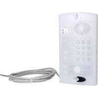
MHF02X - Intercom HAGER - Free user manual and instructions
Find the device manual for free MHF02X HAGER in PDF.



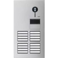
| Product type | Street panel for 2 dwellings with translucent code |
| Brand | Hager |
| Model | MHF02X |
| Category | Intercom |
| Technical box power supply | Lithium battery 2 × (3.6 V 17 Ah) MPU01X + lithium-ion battery 3.6 V 700 mAh or mains power supply 12-24 V AC or 12-30 V DC or solar panel 12 V 8 W min |
| Handset power supply | Removable lithium-ion battery MTU01X (rechargeable) or lithium battery 2 × (3.6 V 17 Ah) in the base |
| Technology | Secure multi-frequency radio, 868-870 MHz, 25 mW max |
| Radio range | Up to 400 m in open field (varies depending on obstacles) |
| Number of dwellings | 2 (with code keypad) |
| Main functions | Intercom, listen-in, inter-handset communication, door release control (up to 2), gate, wicket gate, lighting (up to 4), garage (up to 4) |
| Handset display | Battery status, time, indoor/outdoor temperature, access status, missed calls, control icons |
| Street panel backlighting | Night mode, on action, or 24/7 depending on power supply |
| Protection rating of street panel and box | IP54 / IK08 |
| Handset protection rating | IP31 / IK04 |
| Operating temperature for street panel | -20 °C to +70 °C |
| Operating temperature for handset | -5 °C to +55 °C |
| Handset autonomy away from base | 15 days (domestic use) |
| Technical box autonomy | 5 years with MPU01X battery, 3 years with LR20 batteries (domestic use) |
| Maintenance and cleaning | Clean with soapy water and a soft cloth. Do not use alcohol or acetone |
| Safety | Secure radio link, TBT motor control, ELV inputs/outputs |
| Spare parts and repairability | Consult Hager after-sales service. Batteries and accumulators are replaceable. |
| General information | Compatible with intercom kits SC900AX to SC906AX, indoor units SC100AX/SC101AX, box SC200AX |
Frequently Asked Questions - MHF02X HAGER
User questions about MHF02X HAGER
0 question about this device. Answer the ones you know or ask your own.
Ask a new question about this device
Download the instructions for your Intercom in PDF format for free! Find your manual MHF02X - HAGER and take your electronic device back in hand. On this page are published all the documents necessary for the use of your device. MHF02X by HAGER.
USER MANUAL MHF02X HAGER
SC900AX / SC901AX / SC902AX SC906AX / SC100AX / SC101AX SC200AX / SC201AX / SC206AX MHF01X / MHF02X / MHF03X MHF04X / MHF05X / MHF06X
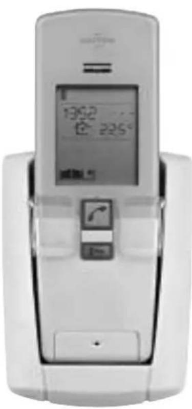
natural_image
Front view of a white mobile phone with a digital display showing time and angle (no visible text or symbols on the device body)SC201AX Coffret technique pile lithium
SC206AX Coffret technique
6.2 Hors communication
7.2 Hors communication
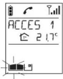
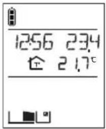
8.2 Hors communication
SUR ACTION MODE NUIT ACTIF
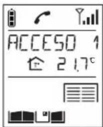
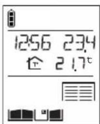
- Pulsar la tecla (0)
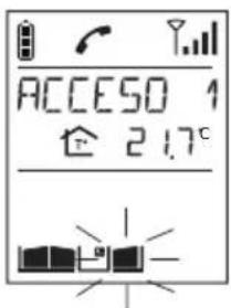
- Pulsar la tecla (1)
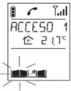
- Pulsar la tecla .0→
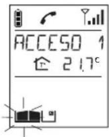
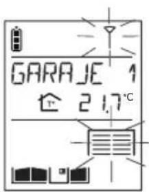
natural_image
Hand inserting a card into a box (no text or symbols visible)
This manual describes how to use the following products:
SC900AX Lithium/lithium 1-button 1-home doorphone kit
SC901AX Mains/mains code-operated 1-home doorphone kit
SC902AX Mains/lithium 1-button 1-home doorphone kit
SC906AX Battery/mains 1-button 1-home doorphone kit
SC100AX Interior handset unit + base + EU power pack
SC101AX Interior handset unit + battery-charging base
SC200AX Mains-powered controller
SC201AX Lithium battery-operated controller
SC206AX Dry battery controller
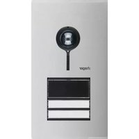
MHF01X Translucent 2-home outdoor caller unit
MHF02X Translucent code-operated 2-home outdoor caller unit
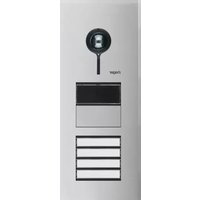
MHF03X Opaque 1-home outdoor caller unit
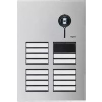
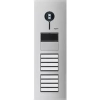
MHF04X Opaque 2-home outdoor caller unit
MHF05X Opaque code-operated 1-home outdoor caller unit
MHF06X Opaque code-operated 2-home outdoor caller unit
Foreword
The doorphone system can be used to welcome and filter visitors, listen in to background sounds at each access point and communicate with another handset.
It can also be used to remotely control:
- one or several electrical latches,
- one or several automatic gate control systems,
- one or several automatic garage door control systems,
- one or several lights.
It also allows users to check the status of access points or lights using the screen on the handset at any time.
Several additional interior handset units can be added to the doorphone system (maximum of 4 per call button).

Waste processing of electrical and electronic devices at the end of their service life (Applicable in European Union countries and other European countries with a waste collection system). Used on products or product packaging, this symbol indicates that the product must not be thrown out with household waste. It must be taken to a waste collection point for electrical and electronic product recycling. When you make sure that this product is disposed of in the most appropriate
manner, you are helping to protect the environment and human health. If you would like additional information concerning the recycling of this product, please contact your town/city council, nearest waste collection centre or the shop where you bought the product.
Contents
1. Overview of handset keys and display.... 112
1.1 Description of handset.... 112
1.2 Description of display 113
1.3 Handset display in standby mode (general information screen) 114
2. Answering a visitor's call.... 114
2.1 Using the handset in handsfree mode (handset on base).... 114
2.2 Using the handset in handheld mode (handset off base).... 115
3. Switching the handset to silent mode.... 116
4. Listen-in function ...... 116
5. Inter-handset communication function.... 117
6. Controlling latch access.... 118
6.1 when communicating.... 118
6.2 when not communicating 119
7. Controlling gate access 121
7.1 when communicating.... 121
7.2 when not communicating....122
8. Controlling side gate access.... 124
8.1 when communicating.... 124
8.2 when not communicating....125
9. Operating an automatic garage door control system.... 127
10. Controlling lighting.... 128
11. Modifying outdoor system operating options.... 129
11.1 How to browse through the menus.... 129
11.2 Modifying tag options.... 130
11.3 Modifying access code options 132
11.4 Modifying display options.... 134
11.5 Modifying sound options.... 135
11.6 Modifying control options.... 136
11.7 Modifying opening options.... 137
11.8 Information 137
12. Modifying handset operating options 138
12.1 How to browse through the menus.... 138
12.2 Modifying display options.... 139
12.3 Modifying sound options 140
12.4 Modifying use options.... 141
12.5 Information 142
13. Fault indications.... 142
14. Questions and Answers 143
15. Technical data.... 144
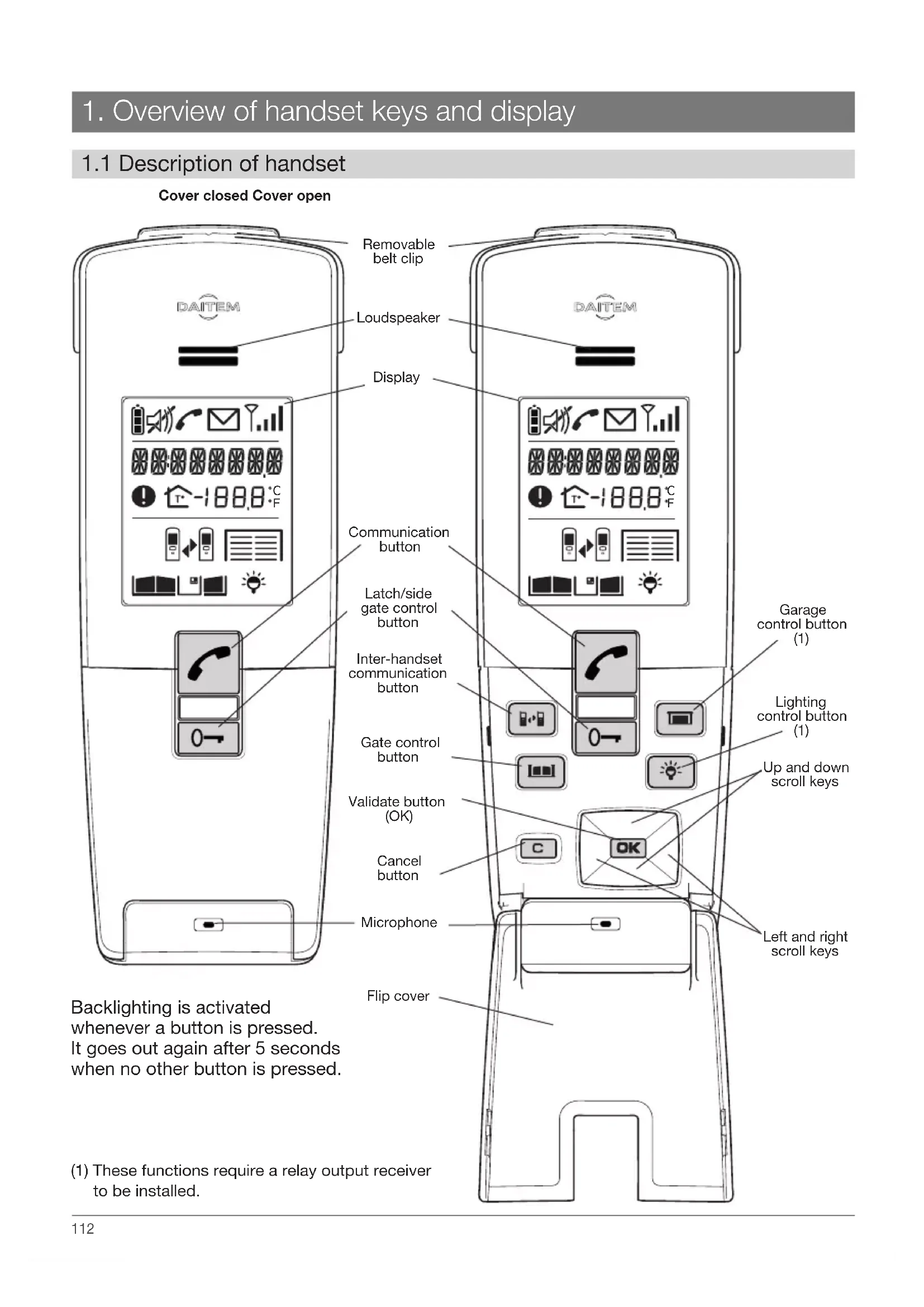
1. Overview of handset keys and display
1.1 Description of handset
Cover closed Cover open
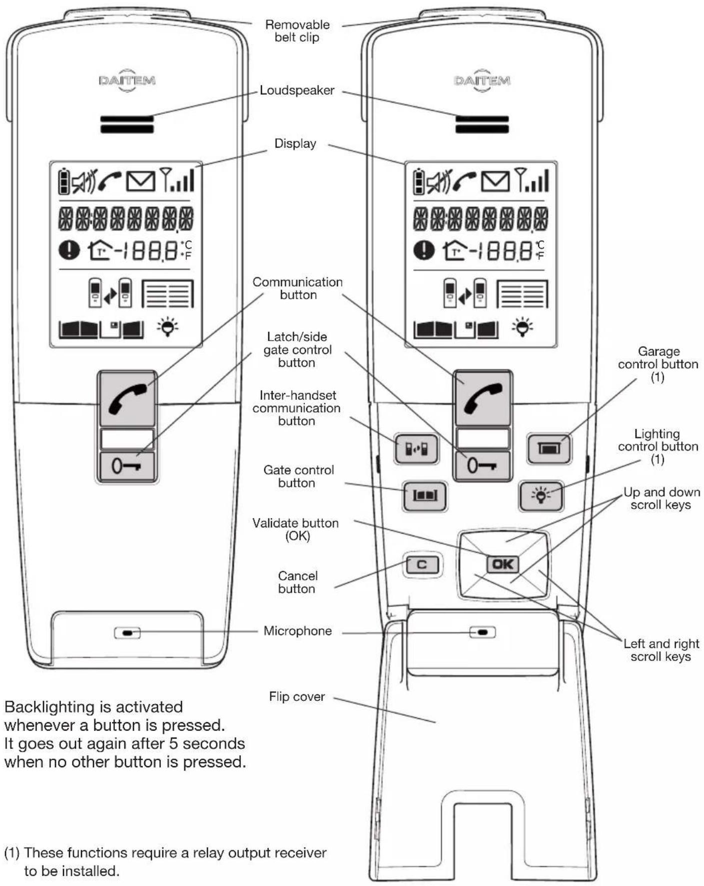
(1) These functions require a relay output receiver to be installed.
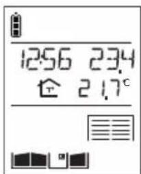
1.2 Description of display
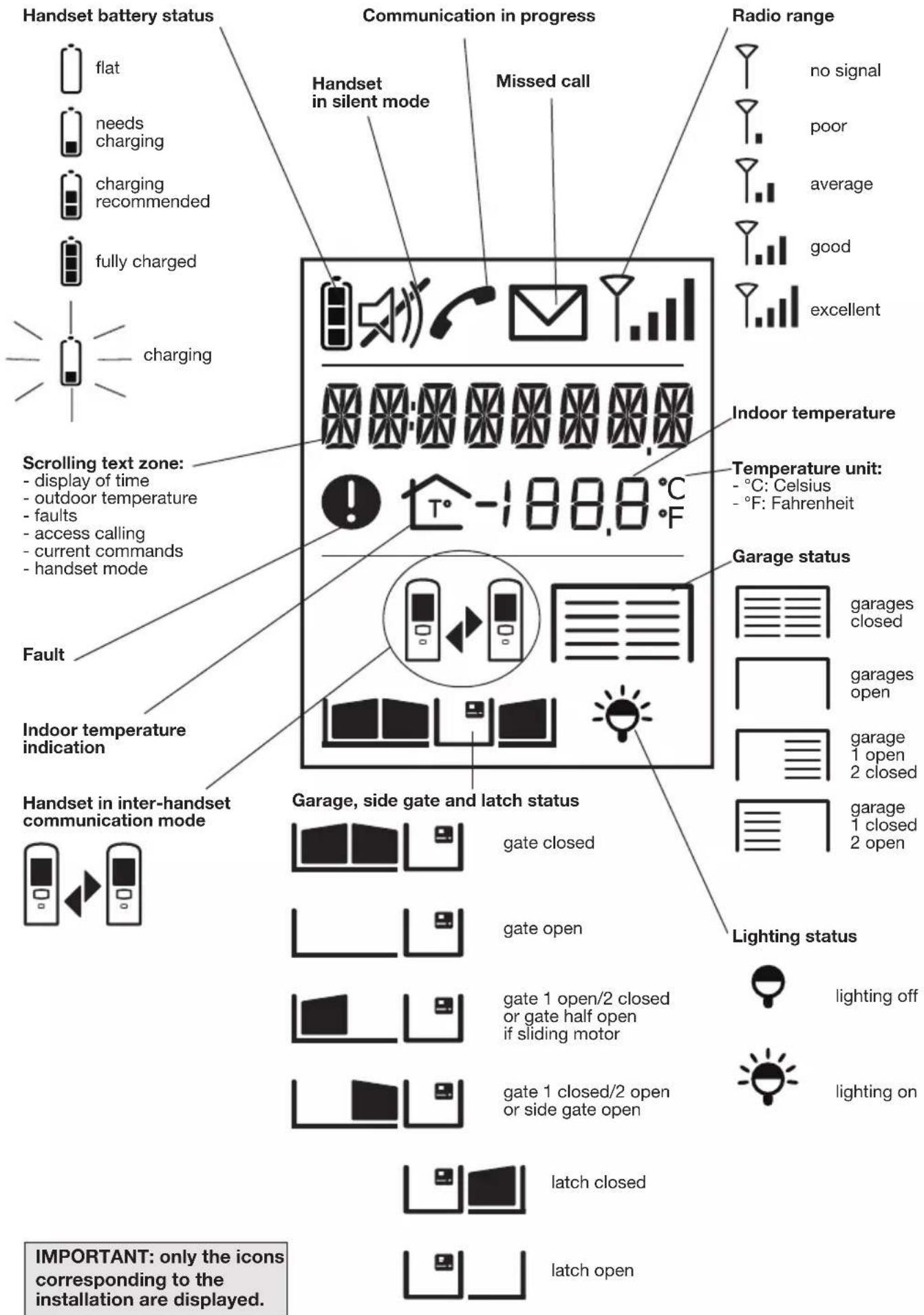
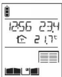
1.3 Handset display in standby mode (general information screen)
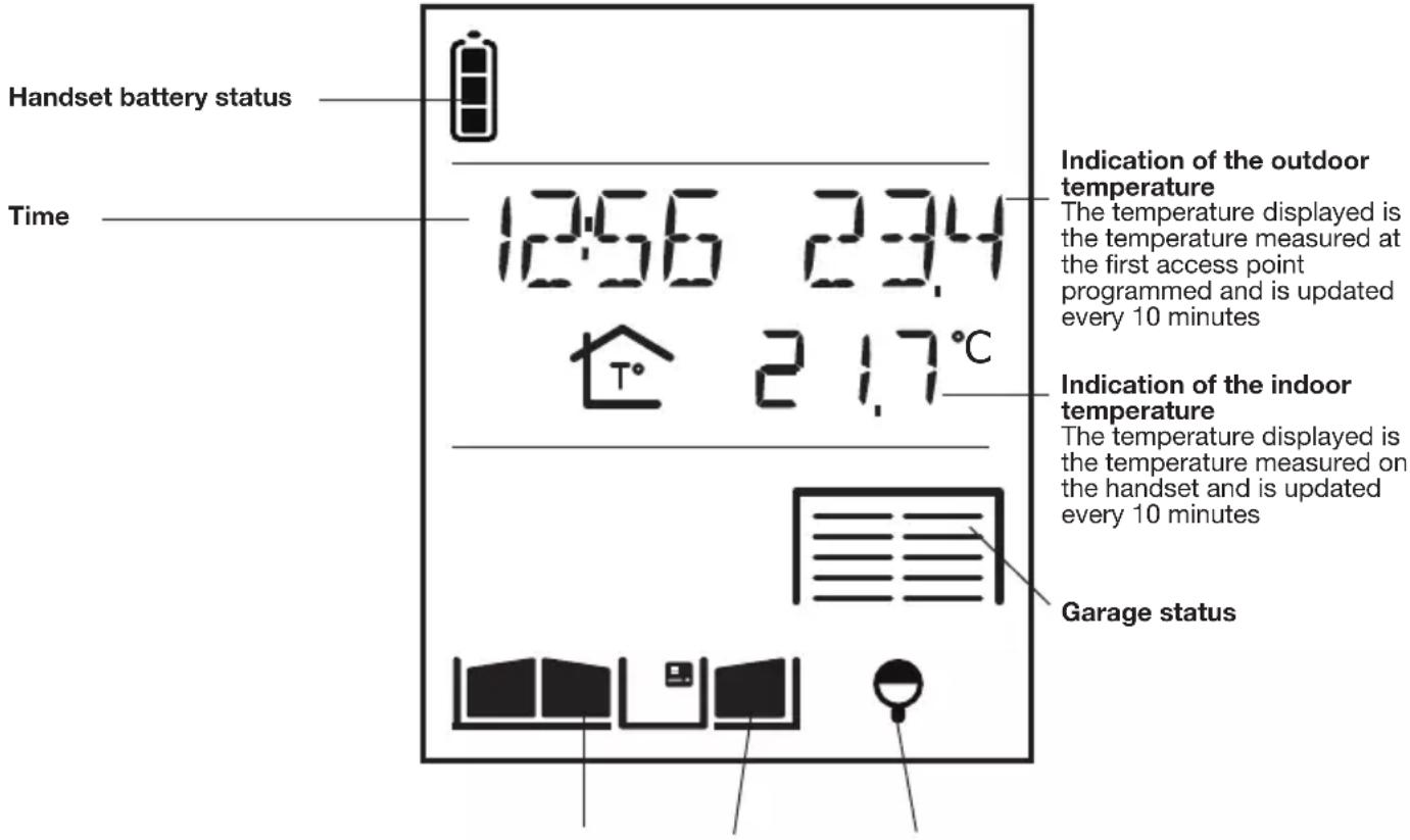
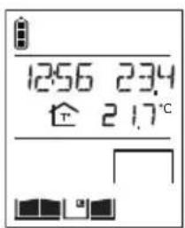
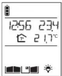
Gate, side gate and latch status Lighting status
IMPORTANT: if the handsets or controllers are too close to each other when you perform different tests, this may cause disturbance (Larsen effects, crackling, etc.). Move the various devices over 3 metres away from each other.
2. Answering a visitor's call
The handset rings (1) (unless it is in silent mode) and the backlighting flashes.
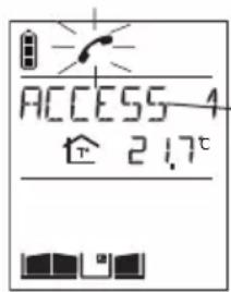
The name of the access point calling (2) is displayed.
(1) If nobody answers, the handset rings for 20 secs (factory setting) and then stops. The duration of ringing can be adjusted (see Programming handset operating options). If the handset is on its base, the handset rings at the programmed volume (see Modifying handset operating options). If the handset is off its base, the ringing volume becomes progressively louder (from level 1 to the programmed level).
(2) The names of access points can be customised (see Modifying doorphone operating options).
2.1 Using the handset in handsfree mode (handset on base)
1. Press
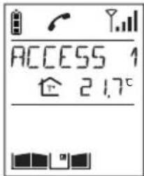
-
You can now talk.
-
At the end of communication, press
If no button is pressed, communication is automatically cut off after 3 minutes.
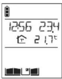
You can switch to "handheld" mode at any time by taking the handset off the base.
2.2 Using the handset in handheld mode (handset off base)
- If the handset is on the base, pick it up:
- if the automatic handheld mode has been activated, communication is established,
- if not, press
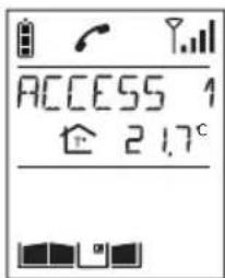
If the handset is already off the base, press.
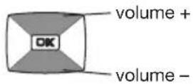
- Open the flip cover to talk and adjust the volume using the keys
- At the end of communication, press
and/or put the handset back on the base (the handset beeps 3 times if it is correctly positioned on the base).
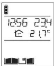
If no button is pressed, communication is automatically cut off after 3 minutes.
3. Switching the handset to silent mode
The handset can be switched to silent mode using the key.
The handset then remains in silent mode for 12 hours or until it is switched back to ringing mode.
- Press for 5 seconds until the icon is displayed.
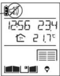
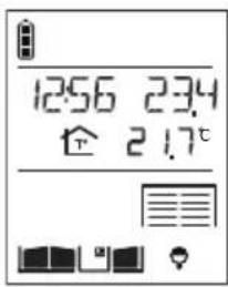
- To switch back to ringing mode, press for 5 seconds until the icon disappears.
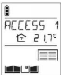
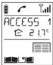
4. Listen-in function
You can listen in to background sounds at the different access points where the outdoor caller units are installed using the key.
-
Quickly press
-
If you have more than 2 access points, select the one you wish to listen in to using the keys

then

If you only have one access point
Listen-in begins and you will hear what is happening at the selected outdoor caller unit and the person in front of the unit will be able to hear you too.
- Press again on to end listen-in.
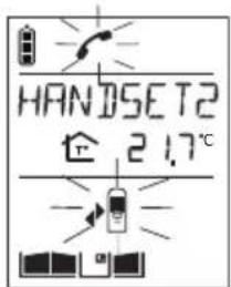
5. Inter-handset communication function
You can communicate with another handset using the key

Handset making the call
- Pick up the handset (if it is on the base), open the flip cover and quickly
press

- If you have more than 2 handsets, select the handset to be called using the keys

then

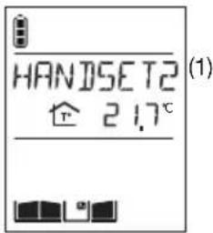
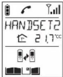
If you have 2 handsets, the inter-handset communication function is activated.
- You can talk and adjust the volume using the keys
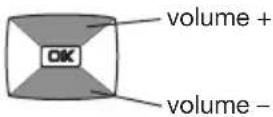
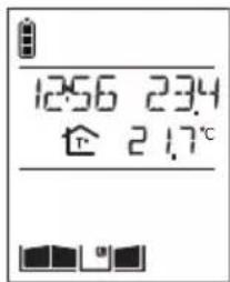
- At the end of communication, press and/or put the handset back on the base.
Handset being called
The handset rings (unless it is in silent mode) and the backlighting flashes. If the handset is on the base, pick it up. Otherwise, press

Open the flip cover and talk, adjusting the communication volume using the keys
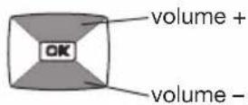
At the end of communication, press and/or put the handset back on the base.
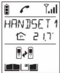
IMPORTANT: if a call is triggered by an outdoor caller unit during inter-handset communication, the outdoor caller unit sounds engaged.
(1) The name of the handset can be customised (see Modifying handset operating options).
6. Controlling latch access
The installation has a latch or a lock and a gate.
6.1 When communicating
You are communicating with access 1, for example.
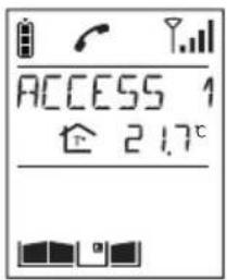
1. Press
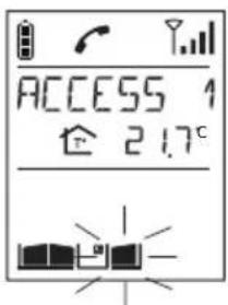
- The latch of the access making the call is unlocked within 5 sec. At the end of communication, the latch status icon is updated (if a position contact is connected).
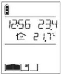
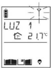
(1) Latch access can be operated using (see HANDSET/CONFIGURATION/OPEN BUTTON menu).
6.2 When not communicating
6.2.1 Using the keypad caller unit
| Activate the outdoor caller unit | Status display on the handset (1) | Latch access status |
| 1. Hold the tag in front of the name label. | ||
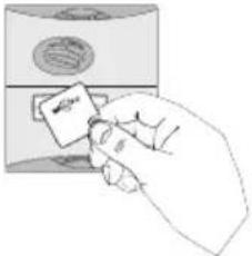 | ||
| Or enter the access code (2). | ||
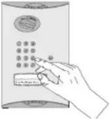 | 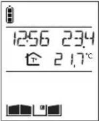 | Closed |
| 2. Press 3. | ||
| 3. The latch is unlocked within 5 seconds. | Open | |
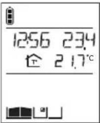 |
(1) If a position contact is connected.
(2) If you press the wrong button, press then enter the access code again.
(3) Only applies to the outdoor caller unit with keypad. If the AUTO COMMAND parameter (see ACCESS/PARAMETERS/AUTO COMMAND menu) is set to ELECTRIC STRIKE, the latch is opened as soon as the tag is held up to the caller unit or the access code is entered. There is then no need to press .
6.2.2 Using the handset
| Activate the handset | Status display on the handset (1) | Latch access status |
| 1. Quickly press [IMAGE] | 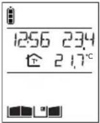 | Closed |
| 2. If you have more than 2 latch access points, pick up the handset (if it is on the base), open the flip cover and select the access point to be opened using the keys[IMAGE]then .OKIf you only have one latch access point, the opening command is sent directly to it. | 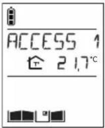 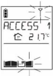 | ClosedOpening command sent |
| 3. The latch is unlocked within 5 seconds. | 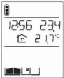 | Open |
(1) if a position contact is connected.
(2) Latch access can be operated using

HANDSET/CONFIGURATION/OPEN BUTTON menu).
7. Controlling gate access
The installation includes a gate and a latch.
7.1 When communicating
You are communicating with access 1, for example.
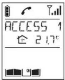
1. Press

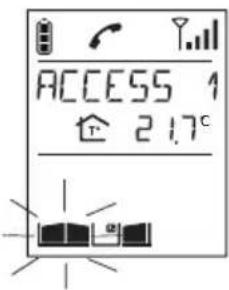
- The gate at the access point making the call is activated within 5 seconds. At the end of communication, the gate status icon is updated (if a position contact is connected).
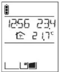
(1) Gate access can be operated using (see HANDSET/CONFIGURATION/OPEN BUTTON menu).
7.2 When not communicating
7.2.1 Using the outdoor caller unit with keypad
| Activate the outdoor caller unit | Status display on the handset (1) | Gate access status |
| 1. Hold the tag in front of the name label. | ||
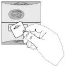 | ||
| Or enter the access code (2). | ||
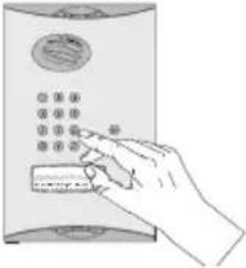 | 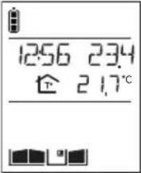 | Closed |
| 2. Press 3. | ||
| 3. The gate is activated within 5 seconds | 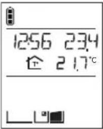 | Open |
(1) If a position contact is connected.
(2) If you press the wrong button, press then enter the access code again.
(3) Only applies to the outdoor caller unit with keypad. If the AUTO COMMAND parameter (see ACCESS/PARAMETERS/AUTO COMMAND menu) is set to GATE, the gate is opened as soon as the tag is held up to the caller unit or the access code is entered. There is then no need to press .
7.2.2 Using the handset
| Activate the outdoor caller unit | Status display on the handset (1) | Gate access status |
| 1. Pick up the handset (if it is on the base), open the flip cover and quickly press (2). | Closed | |
| 2. If you have several gate access points, select the access point to be opened using the keys then OK | Closed | |
| If you only have one gate access point, the opening command will be sent directly to that access. | Opening command sent | |
| 3. The gate is activated within 5 seconds. | Open |
(1) If a position contact is connected.
(2) Gate access can be operated using

8. Controlling side gate access
The installation only has one gate.
8.1 When communicating
You are communicating with access 1, for example.
1. Press
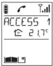
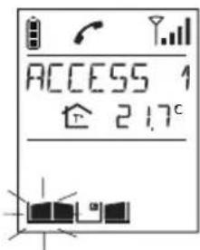
2. The side gate at the access point making the call is unlocked within 5 sec.
At the end of communication, the side gate status icon is updated (if a position contact is connected).
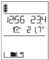
8.2 When not communicating
8.2.1 Using the outdoor caller unit with keypad
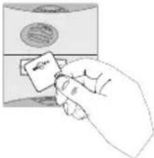
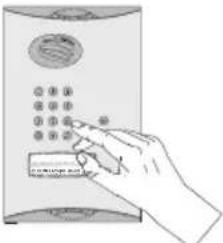
| Activate the outdoor caller unit | Status display on the handset (1) | Side gate access status |
| 1. Hold the tag in front of the name label. | ||
 | ||
| Or enter the access code (2). | ||
 |  | Closed |
| 2. Press 3. | ||
| 3. The side gate is unlocked within 5 seconds. | Open | |
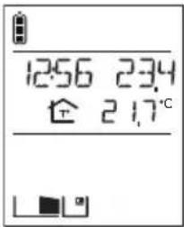 |
(1) If a position contact is connected.
(2) If you press the wrong button, press then enter the access code again.
(3) Only applies to the outdoor caller unit with keypad. If the AUTO COMMAND parameter (see ACCESS/PARAMETERS/AUTO COMMAND menu) is set to ELECTRIC STRIKE, the side gate is opened as soon as the tag is held up to the caller unit or the access code is entered. There is then no need to press .
8.2.2 Using the handset
| Activate the handset | Status display on the handset (1) | Side gate access status |
| 1. Quickly press. | 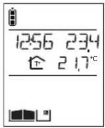 | Closed |
| 2. If you have more than 2 side gate access points, pick up the handset (if it is on the base), open the flip cover and select the access point to be opened using the keys | 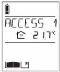 | Closed |
| then. | 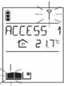 | Opening command sent |
| If you only have one side gate access point, the opening command is sent directly to it. | ||
| 3. The side gate is unlocked within 5 seconds. | 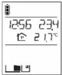 | Open |
(1) If a position contact is connected.
9. Operating an automatic garage door control system
This function requires one or several relay output receivers to be connected.
The k can operate up to four different automatic garage door control systems.
Activate the handset
- Pick up the handset (if it is on the base), open the flip cover and quickly press

- If you have several garages, select the garage to be opened using the keys

then

If you only have one garage, the opening command will be sent directly to it.
- The garage is activated within 5 seconds.
Status display on the handset (1)
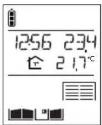

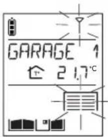
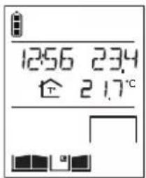
Opening command sent
Open
IMPORTANT: if the key operates:
- 2 automatic garage door control systems, the handset displays:

if both garages are closed,

if both garages are open,

if garage 1 is open and 2 is closed,

if garage 2 is open and 1 is closed.
- more than 2 automatic garage door control systems, the handset displays:

if all the garages are closed,

if all the garages are open,

if at least one garage is open.
(1) If a position contact is connected to the output receiver.
(2) The name of the automatic garage door control system can be customised (see Modifying handset operating options).
10. Controlling lighting
This function requires one or several relay output receivers to be connected.
The key can operate up to four different lights.
| Activate the handset | Status display on the handset | Light status |
| 1. Pick up the handset (if it is on the base), open the flip cover and quickly press | OFF | |
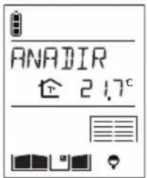
| 2. If you have several lights, select the light to be switched on using the keys then | OFF | |
| If you only have one light, the ON command will be sent directly to it. | ON command sent | |
| 3. The light is activated within 5 seconds. | ON |
(1) The name of the light can be customised (see Modifying handset operating options).
11. Modifying outdoor system operating options
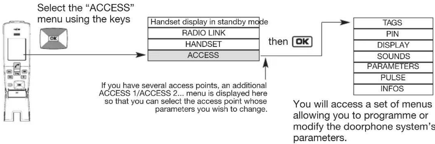
11.1 How to browse through the menus
Pick up the handset and open the flip cover.
flowchart
graph LR
    A["Select the "ACCESS" menu using the keys"] --> B["Handset display in standby mode"]
    B --> C["HANDSET"]
    B --> D["ACCESS"]
    C --> E["then OK"]
    D --> E
    E --> F["TAGS"]
    E --> G["PIN"]
    E --> H["DISPLAY"]
    E --> I["SOUNDS"]
    E --> J["PARAMETERS"]
    E --> K["PULSE"]
    E --> L["INFOS"]
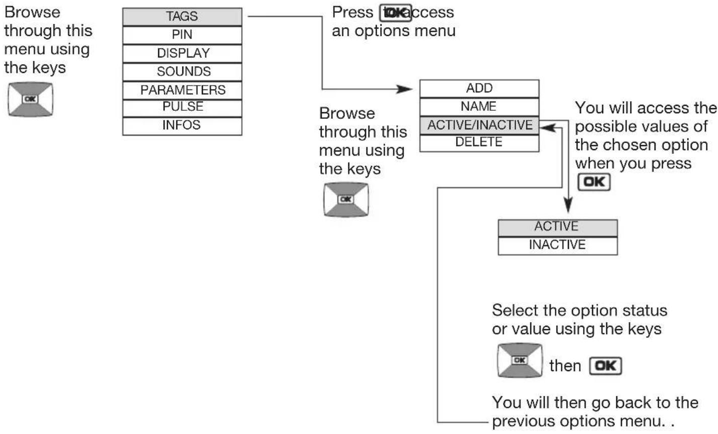
Example of how to browse through the ACCESS menu:
flowchart
graph TD
    A["Browse through this menu using the keys"] --> B["TAGS"]
    B --> C["PIN"]
    C --> D["DISPLAY"]
    D --> E["SOUNDS"]
    E --> F["PARAMETERS"]
    F --> G["PULSE"]
    G --> H["INFOS"]
    I["Press OK access an options menu"] --> J["ADD"]
    J --> K["NAME"]
    K --> L["ACTIVE/INACTIVE"]
    L --> M["DELETE"]
    N["Browse through this menu using the keys"] --> O["OK"]
    O --> P["ACTIVE"]
    P --> Q["INACTIVE"]
    R["Select the option status or value using the keys"] --> S["OK then OK"]
    T["You will then go back to the previous options menu."] --> U["OK"]
- Quickly press to return to the previous display at any time.
- Press and hold to return to the handset display in standby mode.
- If no button on the handset is pressed for 30 sec, the screen returns to the handset display in standby mode.
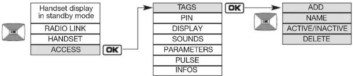
11.2 Modifying tag options
flowchart
graph LR
    A["Handset display in standby mode"] --> B["RADIO LINK"]
    A --> C["HANDSET"]
    A --> D["ACCESS"]
    B --> E["TAGS"]
    C --> E
    D --> E
    E --> F["OK"]
    F --> G["ADD"]
    F --> H["NAME"]
    F --> I["ACTIVE/INACTIVE"]
    F --> J["DELETE"]
    E --> K["PIN"]
    E --> L["DISPLAY"]
    E --> M["SOUNDS"]
    E --> N["PARAMETERS"]
    E --> O["PULSE"]
    E --> P["INFOS"]
| Menu | Setting possible | Using the setting | |
| ADD | Can be used to register a tag on the outdoor caller unit so that a side gate, gate or latch can be opened (16 tags max.).1. Pick up the handset and stand in front of the outdoor caller unit.2. Press once on [AK]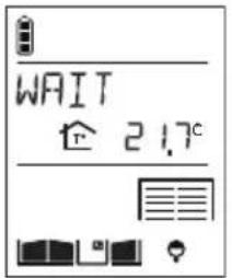 3. Hold the tag to be registered in front of the name label on the outdoor caller unit. 3. Hold the tag to be registered in front of the name label on the outdoor caller unit.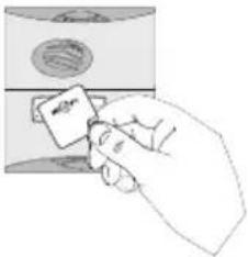 4. Each time a new tag is registered, an additional value is added to the counter. 4. Each time a new tag is registered, an additional value is added to the counter.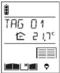 The handset then displays the next screen. The handset then displays the next screen.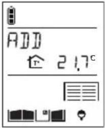 | ||
| Factory: no Programmed tag | |||
| NAME Can be used to change the name allocated to a previously registered tag (8 characters max.). | |||
11.3 Modifying access code options
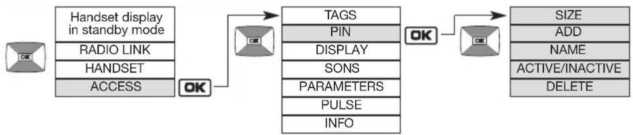
IMPORTANT: the CODES menu is only displayed if the outdoor caller unit has a digicode.
flowchart
graph LR
    A["Handset display in standby mode"] --> B["RADIO LINK"]
    B --> C["HANDSET"]
    C --> D["ACCESS"]
    D --> E["OK"]
    E --> F["TAGS"]
    F --> G["PIN"]
    G --> H["DISPLAY"]
    H --> I["SONS"]
    I --> J["PARAMETERS"]
    J --> K["PULSE"]
    K --> L["INFO"]
    L --> M["OK"]
    M --> N["SIZE"]
    N --> O["ADD"]
    O --> P["NAME"]
    P --> Q["ACTIVE/INACTIVE"]
    Q --> R["DELETE"]
| Menu | Setting possible | Using the setting | |
| SIZE Can be used to define the factory: 4 | 4.5.6 | number of digits (between 4 and 6) for the 16 access codes.To later change the size of the access code, all codes must first be deleted (see DELETE menu). | |
| ADD | Can be used to programme an access code on the outdoor caller unit so that a side gate, gate or latch can be opened (restricted to 16 codes max.).1. Stand in front of the outdoor caller unit with keypad holding the handset.2. Press OK3. Enter the desired 4 to 6-digit code on the outdoor caller unit keypad.4. Each time a new code is entered, an additional value is added to the counter.The handset then moves on to the next screen. | ||
| NAME Can be used to change the name given to an access code that has already been registered (8 characters max.). | |||
11.4 Modifying the display options
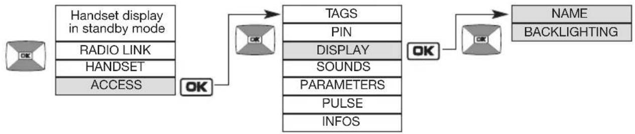
flowchart
graph LR
    A["Handset display in standby mode"] --> B["RADIO LINK"]
    B --> C["HANDSET"]
    C --> D["ACCESS"]
    D --> E["OK"]
    E --> F["TAGS"]
    F --> G["PIN"]
    G --> H["DISPLAY"]
    H --> I["SOUNDS"]
    I --> J["PARAMETERS"]
    J --> K["PULSE"]
    K --> L["INFOS"]
    L --> M["OK"]
    M --> N["NAME"]
    N --> O["BACKLIGHTING"]
| Menu | Setting possible | Using the setting | |
| NAME ACCESS 1KEYPAD 1KEYPAD 2Factory:ACCESS 1 for 1st access, ACCESS 2 for 2nd, etc.KEYPAD 1 for 1st key,KEYPAD 2 for 2nd, etc., as described in the table on the next page | Can be used to modify a name given to an access or to a call button (8 characters max.).Select the name to be modified.Modify the 1^st character using the keys. | 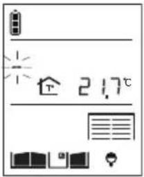 | |
| 3. Move on to the next character using the key.The key selects the previous character. | 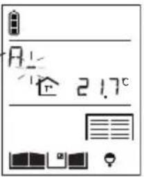 | ||
| 4. Perform steps 2 and 3 for all the characters and then, once the desired name has been programmed, pressOKIMPORTANT: the KEYPAD 1/KEYPAD 2 menu is only displayed if the 2 outdoor caller unit call buttons have been programmed to be recognised by the same handset. | |||
| BACK-LIGHTING | ON ACTION NIGHT MODE ACTIVE | Can be used to define the outdoor caller unit backlighting operating mode.If the controller is connected to an external power supply or a solar panel, you can select the following depending on the type of outdoor caller unit:MHF03X / MHF04X MHF01XMHF05X / MHF06X units MHF02X units | |
| ACTIVE ACTIVE Backlighting is activated 24 hours/day | |||
| NIGHT MODE Backlighting is activated at night time | |||
| ON ACTION ON ACTION Backlighting is activated when a button is pressed or a tag used | |||
| IMPORTANT: if a power cut occurs and the controller has battery back-up, backlighting is activated when a button is pressed or a badge used.If the controller is powered by a solar panel, ACTIVE must be selected. Backlighting will be enabled when a button is pressed or a tag used. | |||
| Menu | Setting possible | Using the setting |
| BACK-LIGHTING (cont.) | Factory: ON ACTION | If the controller is battery-powered, backlighting is activated when a button is pressed or a tag used (the BACKLIGHTING menu is not displayed and no other operating mode is possible). |
| Controller/outdoor caller unit combinations possible | Default message displayed on handset during a call | |
| from1 to 4 controllers with1 outdoor caller unit1 button | 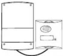 | ACCESS X(with X being from 1 to 4 depending on the controller being called) |
| 1 controller with1 outdoor caller unit2 buttons | 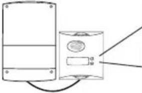 | BUTTON 2orBUTTON 1 |
| from2 to 4 controllers with1 outdoor caller unit2 buttons | 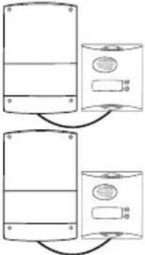 | ACCESS X, BUTTON 1 or BUTTON 2alternately (with X being from 1 to 4 depending on the controller being called) |
11.5 Modifying sound options

flowchart
graph LR
    A["Handset display in standby mode"] --> B["RADIO LINK"]
    B --> C["HANDSET"]
    C --> D["ACCESS"]
    D --> E["OK"]
    E --> F["TAGS"]
    F --> G["PIN"]
    G --> H["DISPLAY"]
    H --> I["SOUNDS"]
    I --> J["PARAMETERS"]
    J --> K["PULSE"]
    K --> L["INFOS"]
    L --> M["OK"]
    M --> N["VOLUMES"]
    N --> O["NIGHT MODE"]
    O --> P["STRIKE SOUND"]
    P --> Q["OK"]
    Q --> R["KEYPAD TONES VOICE"]
| Menu | Setting possible | Using the setting |
| KEYPAD TONES | INACTIVE LOW HIGHFactory: LOW | Can be used to disable or set the volume of a button when it is pressed and of ringing on the outdoor caller unit. The chosen volume can be heard on the outdoor caller unit when the setting is validated. |
| VOICE 1 to 4 | Can be used to set the communication volume on the outdoor caller unit to between 1 (quiet) and 4 (loud). | |
| Factory: 3 | ||
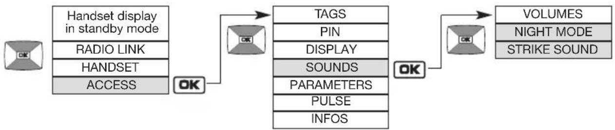
flowchart
graph LR
    A["Handset display in standby mode"] --> B["RADIO LINK"]
    B --> C["HANDSET"]
    C --> D["ACCESS"]
    D --> E["OK"]
    E --> F["TAGS"]
    F --> G["PIN"]
    G --> H["DISPLAY"]
    H --> I["SOUNDS"]
    I --> J["PARAMETERS"]
    J --> K["PULSE"]
    K --> L["INFOS"]
    L --> M["OK"]
    M --> N["VOLUMES"]
    N --> O["NIGHT MODE"]
    N --> P["STRIKE SOUND"]
| Menu | Setting possible | Using the setting |
| NIGHT MODE | ACTIVE INACTIVEFactory: INACTIVE | Can be used to lower the volume of a button when it is pressed or of ringing on the outdoor caller unit (the volume is lowered to QUIET).IMPORTANT: the NIGHT MODE menu is only displayed if the door phone system has been fitted with an MHF01X or MHF02X caller unit. |
| STRIKE SOUND | INACTIVE LOW HIGHFactory: LOW | Can be used to disable or adjust the volume on the outdoor caller unit when an electrical latch is operated. |
11.6 Modifying control options
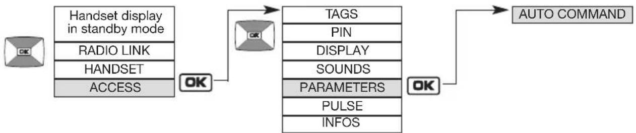
flowchart
graph LR
    A["Handset display in standby mode"] --> B["RADIO LINK"]
    B --> C["HANDSET"]
    C --> D["ACCESS"]
    D --> E["OK"]
    E --> F["TAGS"]
    F --> G["PIN"]
    G --> H["DISPLAY"]
    H --> I["SOUNDS"]
    I --> J["PARAMETERS"]
    J --> K["PULSE"]
    K --> L["INFOS"]
    L --> M["OK"]
    M --> N["AUTO COMMAND"]
| Menu | Setting possible | Using the setting |
| AUTO COMMAND | KEYPAD When a tag is used or a code entered, the system waits for the or key to be pressed in order to open a latch or a gate control system. | Can be used to define the command issued when a tag is detected or a code entered. |
| IMPORTANT: the KEY setting is only displayed if the doorphone system has been fitted with an outdoor caller unit with keypad. | ||
| ELECTRIC STRIKE | Latch opening (or side gate opening or closing if no latch is connected) will be directly triggered when a tag is used or a code entered rendering it unnecessary to press. | |
| GATE Gate opening or closing will be directly triggered when a tag is used or a code entered rendering it unnecessary to press. | ||
| Factory: ELECTRIC STRIKE | ||
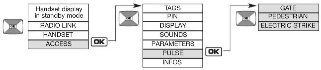
11.7 Modifying opening options
flowchart
graph LR
    A["Handset display in standby mode"] --> B["RADIO LINK"]
    B --> C["HANDSET"]
    C --> D["ACCESS"]
    D --> E["OK"]
    E --> F["TAGS"]
    F --> G["PIN"]
    G --> H["DISPLAY"]
    H --> I["SOUNDS"]
    I --> J["PARAMETERS"]
    J --> K["PULSE"]
    K --> L["INFOS"]
    L --> M["OK"]
    M --> N["GATE"]
    N --> O["PEDESTRIAN"]
    N --> P["ELECTRIC STRIKE"]
| Menu | Setting possible | Using the setting |
| GATE 0.5 SEC | 1 SEC1.5 SEC2 SEC2.5 SECFactory: 2.5 S | Can be used to change the pulse duration for gate motorisation control (terminal blocks 12 and 14). |
| PEDESTRIAN | 0.5 SEC1 SEC1.5 SEC2 SEC2.5 SECFactory: 1 S | Can be used to change the pulse duration for gate motorisation pedestrian opening control (terminal blocks 12 and 14). |
| ELECTRIC STRIKE | 2 SEC5 SECFactory: 5 S | Can be used to change the pulse duration for electrical latch control (terminal blocks 3 and 4). |
11.8 Information

flowchart
graph TD
    A["Handset display in standby mode"] --> B["RADIO LINK"]
    B --> C["HANDSET"]
    C --> D["ACCESS"]
    D --> E["OK"]
    E --> F["TAGS"]
    F --> G["PIN"]
    G --> H["DISPLAY"]
    H --> I["SOUNDS"]
    I --> J["PARAMETERS"]
    J --> K["PULSE"]
    K --> L["INFOS"]
    L --> M["Information for use by the manufacturer."]
12. Modifying handset operating options
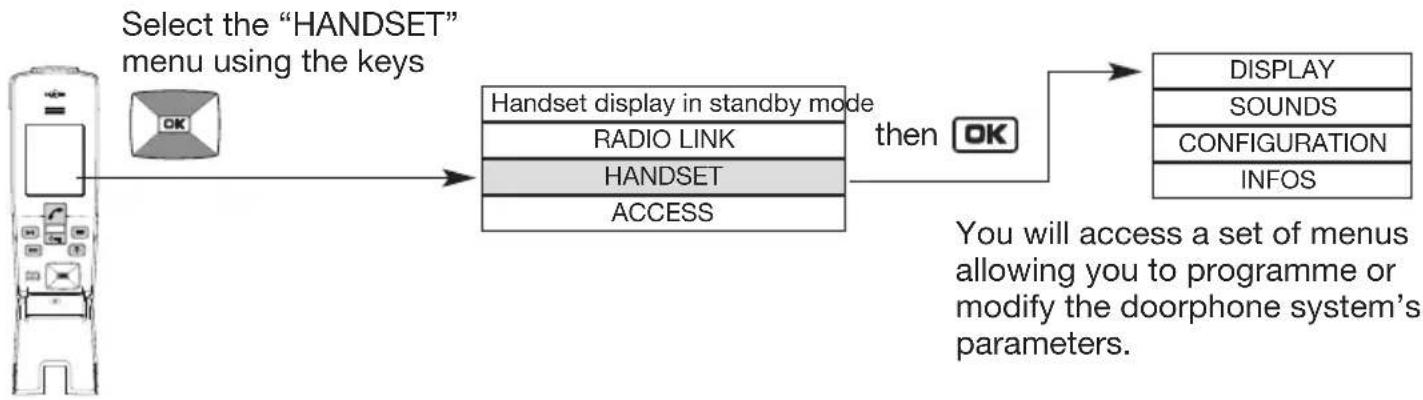
12.1 How to browse through the menus
Pick up the handset and open the flip cover.
flowchart
graph LR
    A["Select the "HANDSET" menu using the keys"] --> B["Handset display in standby mode"]
    B --> C["Radio LINK"]
    B --> D["HANDSET"]
    B --> E["ACCESS"]
    C --> F["then OK"]
    D --> F
    E --> F
    F --> G["DISPLAY"]
    F --> H["SOUNDS"]
    F --> I["CONFIGURATION"]
    F --> J["INFOS"]
    style A fill:#f9f,stroke:#333
    style G fill:#ccf,stroke:#333
    style H fill:#ccf,stroke:#333
    style I fill:#ccf,stroke:#333
    style J fill:#ccf,stroke:#333
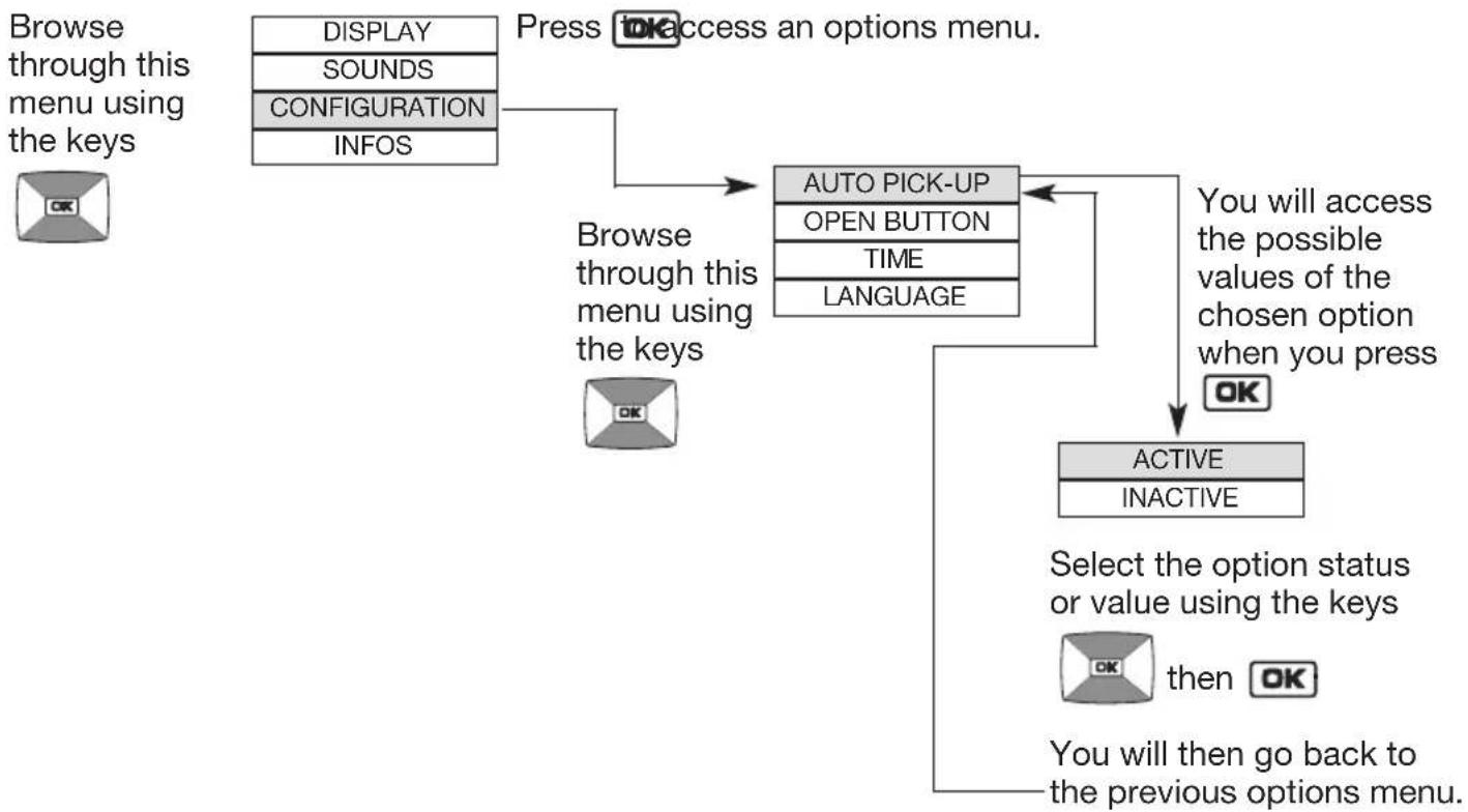
Example of how to browse through the HANDSET menu:
flowchart
graph TD
    A["Browse through this menu using the keys"] --> B["DISPLAY"]
    A --> C["SOUNDS"]
    A --> D["CONFIGURATION"]
    A --> E["INFOS"]
    B --> F["Press OK access an options menu."]
    C --> F
    D --> F
    E --> F
    F --> G["Browse through this menu using the keys"]
    G --> H["AUTO PICK-UP"]
    H --> I["OPEN BUTTON"]
    H --> J["TIME"]
    H --> K["LANGUAGE"]
    I --> L["You will access the possible values of the chosen option when you press"]
    J --> L
    K --> L
    L --> M["ACTIVE"]
    L --> N["INACTIVE"]
    M --> O["Select the option status or value using the keys"]
    N --> P["then OK"]
    O --> Q["You will then go back to the previous options menu."]
- Quickly press to return to the previous display at any time.
- Press and hold to return to the handset display in standby mode.
- If no button on the handset is pressed for 30 sec, the screen returns to the handset display in standby mode.
12.2 Modifying display options

flowchart
graph LR
    A["Handset display in standby mode"] --> B["RSU"]
    C["RADIO LINK"] --> B
    D["HANDSET"] --> B
    E["ACCESS"] --> B
    B --> F["DISPLAY"]
    F --> G["SOUNDS"]
    F --> H["CONFIGURATION"]
    F --> I["INFOS"]
    G --> J["OK"]
    H --> J
    I --> J
    J --> K["DEGREES"]
    J --> L["NAME"]
    J --> M["BACKLIGHTING"]
| Menu | Setting possible | Using the setting |
| DEGREES CELSIUS | FAHRENHEITFactory: CELSIUS | Can be used to change the unit of temperature. |
| NAME Can be used to change the name allocated: | ||
| HANDSET to the handset | ||
| LIGHT 1 | ||
| LIGHT 2 | to a Light control button  | |
| LIGHT 3 | ||
| LIGHT 4 | ||
| GARAGE 1 | ||
| GARAGE 2 | to a Garage control button | |
| GARAGE 3 | ||
| GARAGE 4 | ||
1. Select the name to be changed.2. Modify the 1^st characterusing the keys  | ||
[TIP: press and hold the keys  to quickly scroll through the characters. to quickly scroll through the characters. | ||
3. Move on to the next characterusing the key  The [B24K] selects the previous character. The [B24K] selects the previous character. | ||
| 4. Perform steps 2 and 3 for all the characters and then, oncethe desired name has been programmed, press OK | ||
| BACK - LIGHTING | ACTIVE INACTIVEFactory: ACTIVE | Activates or deactivates handset backlighting.Backlighting is always activated during calls. |
12.3 Modifying sound options

flowchart
graph LR
    A["Handset display in standby mode"] --> B["RADIO LINK"]
    B --> C["HANDSET"]
    C --> D["ACCESS"]
    D --> E["OK"]
    E --> F["DISPLAY"]
    F --> G["SOUNDS"]
    G --> H["CONFIGURATION"]
    H --> I["INFOS"]
    I --> J["OK"]
    J --> K["DOOR BELL"]
    K --> L["SOUND TIME"]
    L --> M["VOLUME"]
| Menu | Setting possible | Using the setting |
| DOOR BELL | Can be used to change ringing when: | |
| ACCESS 1 | a call arrives from access 1 | |
| ACCESS 2 | from access 2 | |
| ACCESS 3 | from access 3 | |
| ACCESS 4 | from access 4 | |
| IINTERCOM or when a call arrives from another handset | ||
| Factory: ACCESS 1: door bell 1 | 1. Select the door bell to be changed. | |
| ACCESS 2: door bell 2 | 2. Choose the desired door bell from among the 9 available and then press OK | |
| ACCESS 3: door bell 3 | ||
| ACCESS 4: door bell 4 | ||
| INTERCOM: door bell 5 | ||
| SOUND TIME | 3 SEC | Can be used to choose the duration of handset ringing. |
| 5 SEC | ||
| 10 SEC | ||
| 20 SEC | ||
| 30 SEC | ||
| Factory: 20 SEC | ||

flowchart
graph LR
    A["Handset display in standby mode"] --> B["OR"]
    C["RADIO LINK"] --> B
    D["HANDSET"] --> B
    E["ACCESS"] --> B
    B --> F["DISPLAY"]
    F --> G["SOUNDS"]
    G --> H["CONFIGURATION"]
    H --> I["INFOS"]
    I --> J["OK"]
    J --> K["DOOR BELL"]
    K --> L["SOUND TIME"]
    L --> M["VOLUME"]
    M --> N["OK"]
    N --> O["TONES"]
    O --> P["KEYPAD TONES"]
    P --> Q["VOICE"]
| Menu | Setting possible | Using the setting |
| TONES INACTIVE1 TO 4Factory: 2 | Can be used to disable or set the handset ringing volume to between 1 (quiet) and 4 (loud). | |
| KEYPAD TONES | INACTIVE LOW HIGHFactory: LOW | Disables or sets the volume of a handset key when it is pressed. |
| VOICE 1 to 4 Sets the handset Factory: 2 | communication volume to between 1 (quiet) and 4 (loud). | |
12.4 Modifying use options

flowchart
graph LR
    A["Handset display in standby mode"] --> B["RADIO LINK"]
    B --> C["HANDSET"]
    C --> D["ACCESS"]
    D --> E["OK"]
    E --> F["DISPLAY"]
    F --> G["SOUNDS"]
    G --> H["CONFIGURATION"]
    H --> I["INFOS"]
    I --> J["OK"]
    J --> K["AUTO PICK-UP"]
    K --> L["OPEN BUTTON"]
    L --> M["TIMELANGUAGE"]
    M --> N["LANGUAGE"]
| Menu | Setting possible | Using the setting |
| AUTO PICK-UP | ACTIVE INACTIVEFactory: ACTIVE | Can be used to automatically establish communication when the handset is picked up off the base without pressing. |
| OPEN BUTTON | Can be used to change the commands associated with the and keys.When the ELECTRIC STRIKE command is selected (factory):The key controls electric strike opening.The key controls gate opening.When the GATE command is selected:The key controls gate opening.The key controls electric strike opening. | |
TIME Can be used to set the time displayedon the handset1. Set the 1stdigit using the keys2. Move on to the next digitusing the key .OKThe key selects the previous character.3. Perform steps 1 and 2 again to set the minutes then, once the chosen time has been programmed, press OK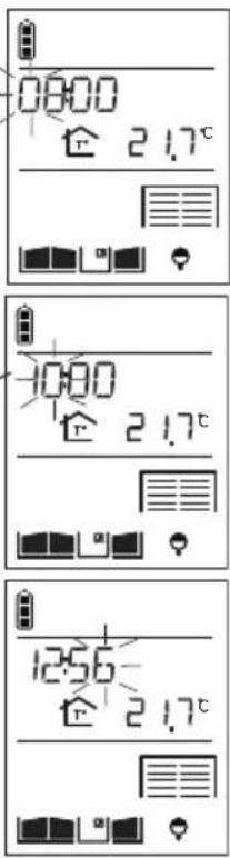 Factory: 00:00 Factory: 00:00 | ||
| LANGUAGE ENGLISHFRANCAIS ITALIANO ESPANOL DEUTSCH NEDERLANDSFactory: ENGLISH | Can be used to set the handset language. | |
12.5 Information

flowchart
graph LR
    A["Handset display in standby mode"] --> B["RADIO LINK"]
    B --> C["HANDSET"]
    C --> D["ACCESS"]
    D --> E["OK"]
    E --> F["DISPLAY"]
    F --> G["SOUNDS"]
    G --> H["CONFIGURATION"]
    H --> I["INFOS"]
    I --> J["Information for use by the manufacturer."]
13 Fault indications
| Display Meaning Solution | |||
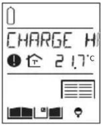 | 7NDSET | Handset battery charge low. | Put the handset back on its base to charge. |
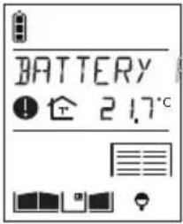 | 3CCES | Controller batteries flat. | Call the installer out to replace the controller batteries. It is advisable to change the handset battery at the same time. |
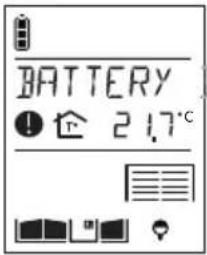 | BASE | Handset base battery flat. | Call the installer out to replace the handset base battery. |
14. Questions and Answers
Questions
Why can conversation be "broken" when using the handset?
What causes the interference (Larsen effect, crackling, etc.) that can be heard in the handset?
Why does the reception quality vary when I move around with the handset?
What should I do if I lose the display on my handset?
What should I do if the handset does not beep and display when I put it back on its base?
Can I clean my doorphone?
What should I do if the handset does not ring during a communication test?
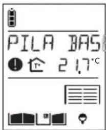
What does the icon displayed on the handset mean?
Answers
This can happen when you are at the radio reception limit. The controller cuts off communication when you go beyond this limit. You should move closer to the controller.
This can happen when the handset is too close to another handset or the controller. Move the various devices over 3 metres away from each other.
If there is no electromagnetic interference or no obstacle between the handset and the controller, the “free field” radio range is roughly 400 m. When the handset is inside the home, the radio range is less. Radio wave propagation is limited depending on the type and thickness of the walls or partitions through which they pass.

Trees or bushes 10% to 30% reduction

Plasterboard and wood 10% to 30% reduction
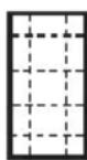
Brick 30% to 50% reduction

Concrete and breeze-block 50% to 70% reduction

Metal and metal cladding 70% to 90% reduction
Simply recharge the handset on its base. The time must be reprogrammed (HANDSET/CONFIGURATION/TIME menu)
Check the mains power supply or the state of the handset base battery.
Use soapy water and a soft cloth to clean products whenever necessary. Do not use alcohol or acetone to clean them.
- Move closer to the controller.
- Check that the handset is not in silent mode (icon displayed).
A visitor came to the outdoor caller unit while you were out. To delete the icon, press on a handset button.
15. Technical data
General data
- Failsafe multi-frequency radio technology with a free field (1) range of up to 400 m, according to environmental and installation conditions
• Radio link: 868 - 870 MHz, 25 mW max, Duty cycle: 0,1%, Rx: category 2
• High-fidelity digital sound
Outdoor caller unit data
- External boxes made of polycarbonate
- Controller and outdoor caller unit degree of protection: IP54/IK08
- Operating temperature from -20^ to +70^
- Controller power supply: 2 x (3.6 V 17 Ah) MPU01X lithium batteries + 1 x (3.6 V 700 mAh) 908-21X lithium-ion battery and/or 12/24 VAC or 12/30V DC power supply and/or 12 V 8 W min. power solar panel, ref. MJU01X or 4 LR20 type 1.5 V alkaline batteries
- 5-year battery life (with MPU01X battery) or 3-year battery life (with 4 LR20 batteries) (2)
- Wiring using 4 wires between the outdoor caller unit and the controller
- Control and powering of any type of low consumption (0.5 A max.) 12 V latches.
- Control of safety ELV motorisation system able to operate with a 48 V DC/1 A dry contact (relay or switch)
- All controller inputs/outputs are SELV types
Internal handset unit data
- Interior boxes made of ABS
• Degree of protection: IP31/IK04 - Operating temperature from -5^ to +55^
- Base powered by: - batteries: MPU01X lithium battery 2 x (3.6 V 17 Ah)
- mains supply: via 220 V/6 V transformer
- Rechargeable handset powered by MTU01X plug-in lithium-ion battery
- Rechargeable handset battery life when off base: 15 days (3)
- Battery base battery life: 5 years (3)
(1) The free field range corresponds to the maximum theoretical distance separating the controller and the handset when there are no obstacles in the way (e.g. wall, screen, vegetation, electromagnetic disturbance, etc.) likely to reduce the range.
(2) The battery life is based on household use, i.e.: 2 x 10-second communications, 7 latch commands and 6 gate commands per day for a controller and an outdoor caller unit without digicode, 1 x 10-second communication, 4 latch commands (without outdoor caller unit backlighting) and 5 gate commands (without outdoor caller unit backlighting) per day for a controller and outdoor caller unit with digicode.
(3) The battery life is based on household use, i.e. 2 x 10-second communications, 2 x 10-second inter-handset communications and 6 commands (2 latch commands, 2 gate commands, 1 lighting command, and 1 garage door command) per day. For the rechargeable handset battery life to last its full period (15 days) when off its base, it must be left on its base to charge for at least 2 days when it is first powered or 4 days if the display screen disappears (during which time it can of course be used).
Hager Security SAS hereby declares that the radioelectric equipment, references SC100AX and SC101AX complie with the requirements of the following 2014/53/EU RE-D directive.
The full text of the EU Declaration of Conformity is available at the address: www.daitem.co.uk.
Non-binding document, subject to modification without notice.
- Hors communication
- Hors communication
- Hors communication
- SUR ACTION MODE NUIT ACTIF
- Foreword
- Contents
- Overview of handset keys and display.... 112
- Answering a visitor's call.... 114
- Switching the handset to silent mode.... 116
- Listen-in function ...... 116
- Inter-handset communication function.... 117
- Controlling latch access.... 118
- Controlling gate access 121
- Controlling side gate access.... 124
- Operating an automatic garage door control system.... 127
- Controlling lighting.... 128
- Modifying outdoor system operating options.... 129
- Modifying handset operating options 138
- Fault indications.... 142
- Questions and Answers 143
- Technical data.... 144
- Overview of handset keys and display
- Description of handset
- Handset display in standby mode (general information screen)
- Answering a visitor's call
- Using the handset in handsfree mode (handset on base)
- Press
- Using the handset in handheld mode (handset off base)
- Switching the handset to silent mode
- Listen-in function
- If you only have one access point
- Inter-handset communication function
- Handset making the call
- Handset being called
- Controlling latch access
- When communicating
- When not communicating
- Using the keypad caller unit
- Using the handset
- Controlling gate access
- When communicating
- When not communicating
- Using the outdoor caller unit with keypad
- Using the handset
- Controlling side gate access
- When communicating
- The side gate at the access point making the call is unlocked within 5 sec.
- When not communicating
- Using the outdoor caller unit with keypad
- Using the handset
- Operating an automatic garage door control system
- Activate the handset
- IMPORTANT: if the key operates:
- Controlling lighting
- Modifying outdoor system operating options
- How to browse through the menus
- Modifying tag options
- Modifying access code options
- Modifying the display options
- Modifying sound options
- Modifying control options
- Modifying opening options
- Information
- Modifying handset operating options
- How to browse through the menus
- Modifying display options
- Modifying sound options
- Modifying use options
- Information
- Fault indications
- Questions and Answers
- Questions
- Answers
- Technical data
- General data
- Outdoor caller unit data
- Internal handset unit data
Brand : HAGER
Model : MHF02X
Category : Intercom