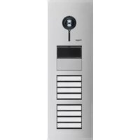
REQ608X - Intercom HAGER - Free user manual and instructions
Find the device manual for free REQ608X HAGER in PDF.


| Product Type | Intercom |
| Brand | Hager |
| Model | REQ608X |
| Dimensions (W x H x D) | 140 x 90 x 30 mm |
| Weight | 200 g |
| Power Supply | 12 V DC, 200 mA |
| Audio Communication | Full-duplex, hands-free |
| Door Release Function | Yes, electric strike control |
| Call Button | Integrated call button |
| Number of Buttons | 1 (call/hang-up) |
| LED Indicators | Power and call status |
| Installation Type | Flush mounting (requires back box) |
| Material | ABS plastic, white finish |
| Protection Rating | IP20 (indoor use only) |
| Operating Temperature | 0 °C to 40 °C |
| Compatibility | Compatible with Hager door stations |
| Wiring | 2-wire bus connection |
| CE Marking | Yes |
| Maintenance | Clean with a soft, dry cloth |
| Spare Parts | Available from Hager (e.g., screws, back box) |
| Warranty | 2 years (subject to conditions) |
Frequently Asked Questions - REQ608X HAGER
User questions about REQ608X HAGER
0 question about this device. Answer the ones you know or ask your own.
Ask a new question about this device
Download the instructions for your Intercom in PDF format for free! Find your manual REQ608X - HAGER and take your electronic device back in hand. On this page are published all the documents necessary for the use of your device. REQ608X by HAGER.
USER MANUAL REQ608X HAGER
natural_image
Simple line drawing of a magnifying glass above a grid of horizontal lines (no text or symbols)2D
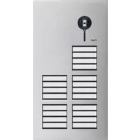
REQ5..X, REQ6..X
Door station VIDEO 2-wire
Safety instructions
GB
Electrical equipment may only be installed and assembled by a qualified electrician in accordance with the relevant installation standards, guidelines, regulations, directives, safety and accident prevention regulations of the country.
When installing and laying cables, always comply with the applicable regulations and standards for SELV electrical circuits.
These instructions are an integral component of the product and must be retained by the end user.
Design and layout of the device

Figure 1: Front
(1) Front plate stainless steel
(2) Microphone
(3) Camera
(4) Locating screw for camera (Allen key supplied)
(5) Twilight sensor for call button/loudspeaker
(6) Button panel with call push-buttons
(7) Cover strip for dismantling protection

Figure 2: Back
(8) Adjustment button Upwards
Δ
(9) 7-segment display
(10) Selection button
(11) Adjustment button downwards ▼
(12) Module connecting cable
(13) Connection terminal block
Function
The door station video works in the 2-wire bus system and enables communication via sound and image.
Correct use
- for surface- or flush-mounted installation in special housings (see Accessories)
- Not compatible with intercom systems of other manufacturers
- suitable for use exterior applications
Product characteristics
- completely pre-assembled
- protected against vandalism
- with brushed 2 mm stainless steel front plate
- Name plate can be changed from the front without any special tools
- One-man commissioning
- Call push-button with acknowledge tone (can be switched off) and tactile feedback
- Call button, light release or door release can be adjusted even without any function
- durable, homogeneous, white LED call push-button backlighting
- Twilight controlled call push-button backlighting with adjustable switch-on brightness level
- Opening of door station only with enclosed opening tool
- break-proof fl ush-mounted call buttons
- Colour camera
- invisible, glare-free IR LED night lighting
- temperature controlled camera heating for clear view
- scratch-proof camera cover
- Loudspeaker and microphone protected against sabotage
- Volume and microphone sensitivity settable
- Door release contact on 1 ... 10 s adjustable
- Door release without previous call adjustable in single door systems
- Safety rope as installation aid
Operation
Establish call (ringing)
- Press the call push-button assigned to the desired subscriber.
If configured, the call push-button activation is confirmed by an acknowledge tone. Addressed indoor stations are called.
Switch-on lights
A call push-button is configured and labelled for lighting control (light insert supplied).
- Press the call push-button for lighting.
If confirmed, the call push-button activation is confirmed by an acknowledge tone. The light contact of a line power supply is closed for the set time.
Label call push-button
- Keep call push-button pressed on one side. On the opposite side, the lever opening (14) is accessible for a screwdriver.
- Position the screwdriver in the lever opening (14) and release the interlock (Figure 3).
- Remove cover with name plate insert.

Figure 3: Removing name plate cover
(14) Lever opening
- Label name plate insert if required.
- Insert name plate insert, prepared foil or prepared labelling strip into the cover and press on cover.
Do not use any paper for the name plate insert, since moisture and UV light will damage the paper and labelling.
D V-resistant foil with laser printing is suitable for labelling as well as labelling devices for labelling strip:
- small buttons - 12 mm
- medium buttons - 30 mm
Door stations with status indication
| Dis-play | Cause Function | h/Lighting duration |
| A subscriber is called. | After 90 s without call acceptance or an operation on the door station, goes out. | |
| A subscriber accepts the door call. | goes out, lights up as long as the intercom connection is pressed down, max. 3 min. | |
| The door is unlocked. | Call not accepted: Symbol goes out and lights up for the unlocking time set on the door station. Call accepted: In addition to the lights up for the unlocking time set on the door station. goes out approx. 5 sec after the symbol. |
Table 1: Status indications of door station
Cleaning and care
Commercially available products for stainless steel and car paintwork care containing a wax component for conservation are recommended for cleaning and care.
Do not use wire wool, wire brushes or any similar products for cleaning. This will prevent damage to the surface and accumulation of flash rust.
Information for electricians
Installation and electrical connection

DANGER!
Touching live parts in the installation environment can result in an electric shock!
An electric shock can be lethal!
Before working on the device or load, disconnect all associated circuit breakers. Cover all live parts in the area!
When installing door communication systems, comply with the general safety regulations for telecommunications systems according to VDE 0800:
- Separate routing of power and door communication cables with a minimum spacing of 10 cm
- Partitions between power and door communication cables in shared trunkings
- Use of standard telecommunications' cables, e.g. J-Y (St) Y with 0.8 mm diameter
Bus cables
- J-Y(ST)Y or A-2Y(L)2Y Use wrapped wire pair. Recommendation white/yellow
- CAT Use wrapped wire pair Recommendation orange/white
- YR Use adjacent wires
Mounting door station
Surface-mounted or flush-mounted housing is installed (see Assembly instruction housing). The connection cables and indoor stations are connected to the line power supply while taking the maximum cable lengths and attenuations into account (see operating instructions of the line power supply).
- The fastening elements supplied with the fl ush-mounted housing must be assembled. To do this, loosen the nuts on the threaded bolts, slide the elements onto the bolts over the 2 nuts and then tighten.
The support bracket (15) of the fastening elements must be located on the wall surface (Figure 4).
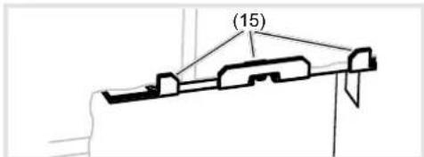
Figure 4: Installation position of fastening elements (15) Support bracket of the fastening elements
- Insert opening tool (16) into the mounting device of the lower fastening element (17) on the housing (Figure 5).

Figure 5: Inserted opening tool
(16) Opening tool
(17) Fixing element
- Attach the loops of the safety rope (17) to the upper left suspension of the door station and to the upper fastening element (16) in the housing. Place the door station for installation onto the opening tool (Figure 5).
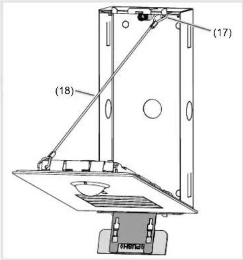
Figure 6: installation position of door station
(18) Safety rope
Connect door station
- Shorten connection cable of the door station and strip the required wires.
- Pull off connection terminal block (13) from the video insert.
- Connect the wire pair of the 2-wire bus cable to the terminals XX of the connection terminal block (Figure 7).
- Connect door release to the terminals TT of the connection terminal block (figure 7 and 8) if required.
or:
- For manipulation-protected installation, connect the door release to the contact □ of the line power supply (Figure 9).
The door release lead must not be inserted through the door station in order to protect against manipulation.
- For call push-button backlighting and camera heating connect 12 V\~ lead from the power transformer to the terminals \~\~ of the connection terminal block (Figure 7).
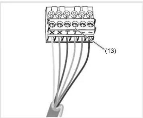
Figure 7: Wired connection terminal block
Information on the connection as a floor door station can be found in the operating instructions of the line power supply.
- Attach connection terminal block to video insert.
Circuit symbols and elements of the circuit diagrams

Line power supply RMD

Power transformer

Door release

Video door station

Wrapped wire pair for 2-wire devices
(recommendation: white/yellow wire pair)

Unwrapped wire pair, for e.g. for door release

Figure 8: Door release connection on the door station

Figure 9: Connection of door station video with manipulation-protected door release
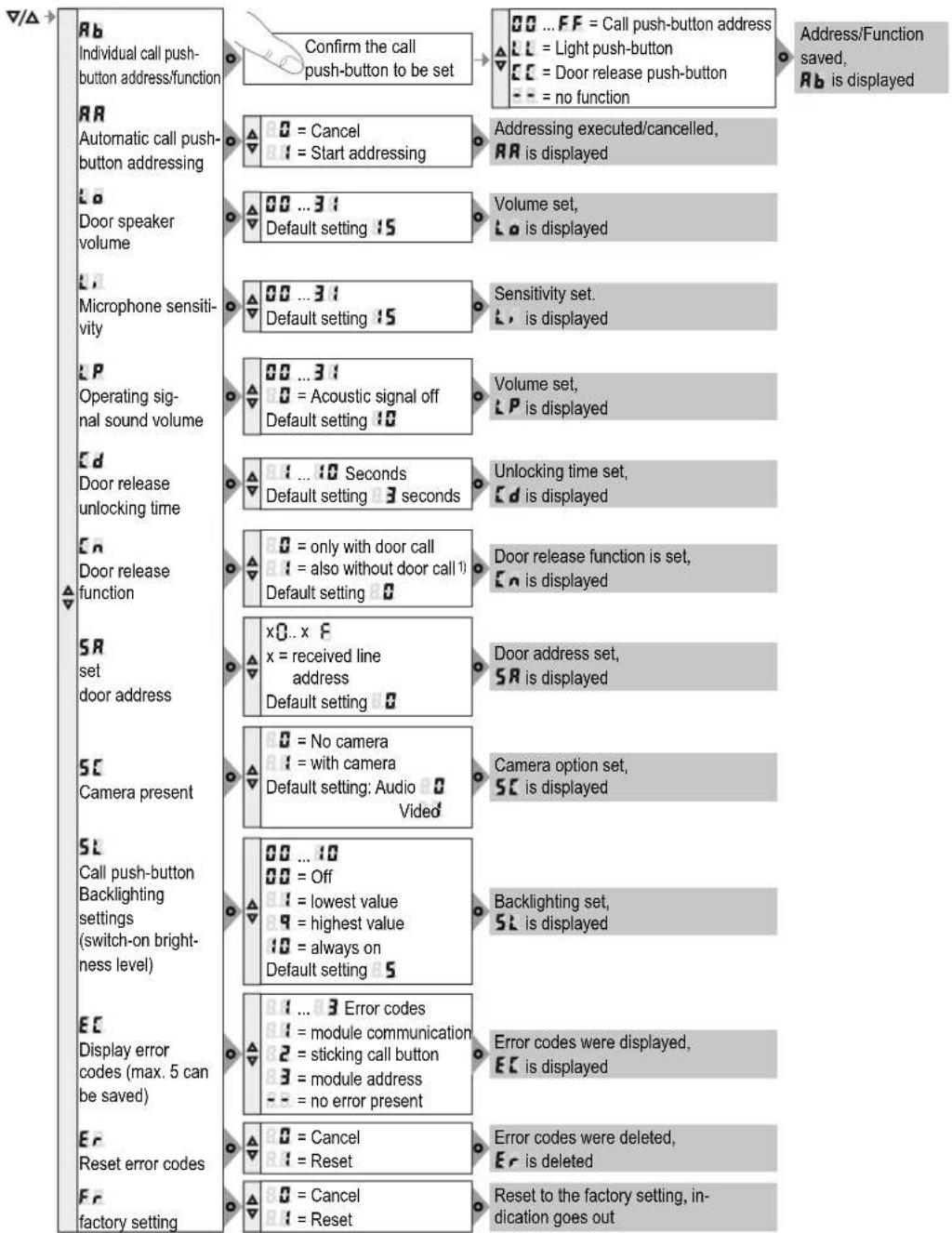
flowchart
graph TD
    A["Individual call push-button address/function"] --> B["Confirm the call push-button to be set"]
    B --> C{0 = Cancel}
    B --> D{1 = Start addressing}
    C --> E["Addressing executed/cancelled, RR is displayed"]
    D --> F["Door speaker volume"]
    F --> G{00 ... 31}
    G --> H["Default setting 15"]
    H --> I["Volume set, Lo is displayed"]
    F --> J{00 ... 31}
    J --> K["Default setting 15"]
    K --> L["Sensitivity set, L is displayed"]
    F --> M{00 ... 31}
    M --> N{0 = Acoustic signal off}
    M --> O["Default setting 10"]
    O --> P["Volume set, LP is displayed"]
    F --> Q["Door release unlocking time"]
    Q --> R{01 ... 10 Seconds}
    R --> S["Default setting 3 seconds"]
    S --> T["Unlocking time set, Cd is displayed"]
    F --> U{0 = only with door call}
    U --> V{01 = also without door call 11}
    V --> W["Default setting 0"]
    W --> X["Door release function is set, En is displayed"]
    F --> Y["SDset door address"]
    Y --> Z{x0..x F}
    Z --> AA["x = received line address"]
    AA --> AB["Default setting 0"]
    X --> AC["Door address set, SR is displayed"]
    Y --> AD{0 = No camera}
    AD --> AE{01 = with camera}
    AE --> AF["Default setting: Audio Vided"]
    AF --> AG["Camera option set, SC is displayed"]
    Y --> AH["SCamera present"]
    AH --> AI{00 ... 10}
    AI --> AJ{00 = Off}
    AJ --> AK{01 = lowest value}
    AK --> AL{09 = highest value}
    AL --> AM{10 = always on}
    AM --> AN["Default setting 5"]
    AH --> AO["Call push-button Backlighting settings (switch-on brightness level)"]
    AO --> AP{01 ... 3 Error codes}
    AP --> AQ{01 = module communication}
    AQ --> AR{2 = sticking call button}
    AR --> AS{3 = module address}
    AS --> AT{-- = no error present}
    AO --> AU{Error codes were displayed, EC is displayed}
    AU --> AV{0 = Cancel}
    AV --> AW{01 = Reset}
    AW --> AX{Reset to the factory setting, in-dication goes out}
1) Door release functions without door call only possible single door systems
Figure 10: Overview of system settings
Calling up and changing of system settings
On the back of the video insert, there are 3 operating buttons and a 2-digit 7-segment display (Figure 2, 8 - 11).
- Press / ▲utton.
Device turns to setting mode. The first menu entry Rb is displayed.
The reading directions of the 7-segment display varies by 180^ depending on which button / you start with.
- Select the desired menu entry with / ▲ (figure 10).
- Confirm the selection with
The 7 segments display goes dark if there is no actuation for 5 seconds. Settings are applied. The device returns to normal operation.
Setting the values
The menu entry to be set is confirmed and flashes alternately with the value to be set.
- Press / ▲utton.
Short button-press: change the value by one step.
Long button-press: run through values. Scrolling stops when the button is released.
- Confirm set value with
The device applies the setting and returns to the previous menu entry.
Address call push-button automatically RR
The call push-button and connector on the back are addressed by the automatic call push-button addressing as follows. The addressing takes place starting from the top downwards, and with a two-rowed door station, counterclockwise automatically upwards to the right (figure 11).
Door stations are automatically pre-confi gured at the factory.
The menu entry RR is selected. RR ashes alternately with the entry for cancel.
- WIV / ▲ select the entry for automatic addressing.
- Confirm with
During the addressing, the display fl ickers. Afterwards the display returns to the previous menu entry R R.

Figure 11: Module address and automatic call push-button addressing
Set individual call push-button address/function Rb
The menu entry R set individual call push-button address/function is selected and fl ashes.
- Confirm the call push-button to be set. The menu entry Rb fl ashes alternately with the current address/function.
- With / Select the required address .00 FF or function L for light push-button, for door release push-button or -- for no function.
- Confirm set address/function with .
The device applies the setting and returns to the previous menu entry. Rb.
Display saved error codes EC
Video insert and call-button module errors that occur during operation are stored in the error memory of the video insert for diagnosis.
- Select menu entry with button ▼ and confirm with○
If no error code exists -is displayed for 2 seconds and afterwards EC.
If error codes are saved EC fl ashes followed by the module address and the error code.
- Press button / ▲ to call up further error codes if necessary.
- Press button to return to menu entry
| Error code | Error cause Counter actions | |
| 8.1 | Communication error between camera insert and call push-button module. Once the error has occurred 3 times, the system is reset automatically and the error code is generated. | If the error persists, the call push-button module must be replaced. |
| 8.2 | sticking call button Check | ck call push-button module, and if there is a defect, replace and address. |
| 8.3 | Writing of the call push-button address in the call push-button module fails. | If the error persists, the call push-button module must be replaced and addressed. |
Table 2: Error codes and counter actions
The memory should only be deleted once 5 error codes have been stored, so that new error codes can be saved.
Identical error codes are only saved once.
Inserting door station
The system settings are complete.
- Remove opening tool from housing.
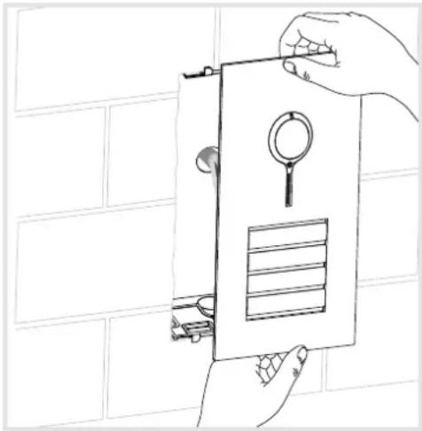
- Insert door station and press down until it clicks audibly into place simultaneously at the top and bottom if possible (Figure 12).
natural_image
Line drawing of hands holding a wall-mounted device with a magnifying glass and grid panel, against a brick wall background (no text or symbols)Figure 12: Insert door station
Align camera
The camera can be aligned in order to adapt the camera picture to the local circumstances (Figure 14 and 15).
The door station is installed.
- Loosen the locating screw for the camera 1.5 mm with the Allen key supplied (Figure 13).
- Call an indoor station video from the door station by call push-button.

Figure 13: Alignment of the camera
- Align camera (fi gure 14/15).
The entrance area is clearly visible on the display of the indoor station.
● Fix camera again with screw (4).
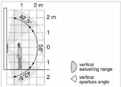
Figure 14: Vertical camera orientation

Figure 15: Horizontal camera orientation
Dismantle call push-button module cover
During cleaning or replacement, the call push-button module cover can be dismantled from the front.
- Lever up the interlocking cover strips (7) at the top and bottom using the screwdriver and remove (Figure 16).

natural_image
Technical line drawing showing a magnifying glass above a grid-patterned panel with a tool inserted, no text or symbols present.Figure 16: Removal of cover strips
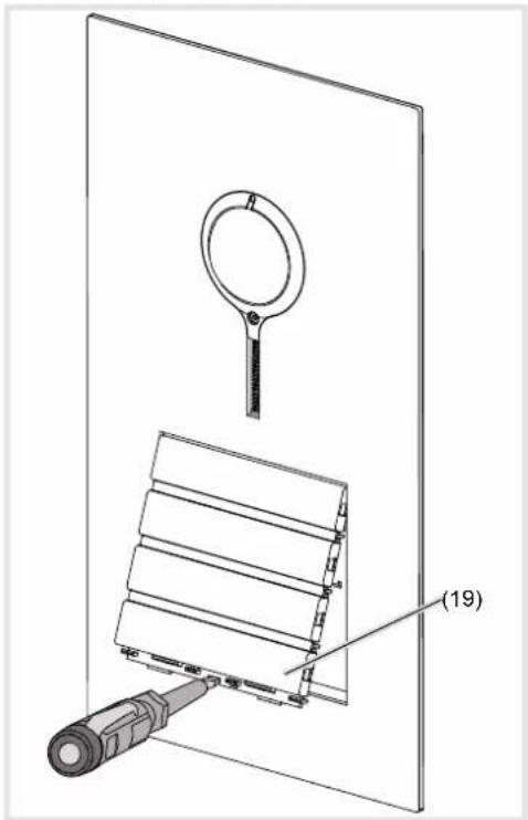
- Press up the call push-button module cover in the bottom lever opening with the screwdriver and guide it forwards (17).
natural_image
Technical line drawing of a device with a magnifying glass and a labeled component (19), no readable text or symbols present.Figure 17: Dismantling the call push-button module cover
(19) Call push-button module cover
Defective covers can only be replaced by co-vers with the same number of push-buttons.
- Remove the module to be replaced and install the new module in reverse order.
Open door station
- Position the opening tool (16) at the bottom in the middle and press up (Figure 18).
With two-series door stations, use the opening tool in the middle under each series of call push-buttons.
The door station will spring out of the bottom interlocking mechanism forwards and can be opened.

Figure 18: Opening of the door station
Exchange module/insert
Door station is dismantled.
- Pull off connection terminal block (13) on the video insert.
- Remove the connection cables' connectors of the module to be exchanged.
- Loosen screws (20) of the module mounting at the back (21) using a screwdriver and remove the module mounting (Figure19).

Figure 19: Dismantling module mounting
(20) Screws
(21) Module mounting
The video insert can now be removed.
- To remove the call push-button module, unlatch the side retaining brackets (22) of the module mounting by carefully lifting up with a screwdriver (Figure 20).

Figure 20: Unlatching module
(22) Retaining brackets module mounting
After unlatching the two overlapping module retaining brackets, the module detaches itself from the anchoring (22).
- Remove the module to be replaced and install the new module in reverse order.
Automatic or manual addressing of the module is required to operate the door station.
Appendix
Technical data
| Operating voltage | 22 ... 24 V= |
| Camera standby current consumption | approx. 8 mA |
| Camera current consumption (operation) | max. 240 mA |
| Camera heating current consumption (operation) | 100 mA |
| Current name plate lighting per call push-button module | 45 mA |
| Menu setting | Backlighting On | Backlighting Off |
| 0 | Permanent Off | |
| 1 | ≈750 lx | ≈1600 lx |
| 2 | . | . |
| 3 | . | . |
| 4 | . | . |
| 5 | . | . |
| 6 | . | . |
| 7 | . | . |
| 8 | . | . |
| 9 | ≈60 lx | ≈110 lx |
| 10 | Permanent On | |
Table 3: Brightness of LED backlighting
Door release contact T/T
| potential-free | max. 24 V/1 A |
| Door release unlocking time | 1 ... 10 s |
Camera aperture angle horiz./vertical 82°/58°
Aperture angle swivelling range
| horizontal/vertical | 42.5° |
| Camera resolution | 500 x 582 px |
Recommended camera installation height 1.5 m
Hexagon 1.5 mm camera
locating screw M2 x 10 mm
Degree of protection IP 44
Degree of protection
(degree of impact resistance) IK07
Relative humidity 0 ... 65% (no condensation)
Operating temperature -20^ +55^
Switch on temperature camera heating ca. 20°C
Storage/transport temperature -30^ +80^
Connecting terminals
for conductor diameter 0.5 ... 0.8 mm
Dimensions:
Call push-button button small 75.8 x 14.5 mm
Name plate insert small 72.1 x 12 mm
Call push-button button medium-seize 75.8 x 32.6 mm
Name plate insert medium-sized 72.1 x 30.1 mm
Width of name plate insert max. 0.5 mm
Surface compensation with
fl ush-mounted installation max. 17 mm
Dimensions video door station front (W x H x D):
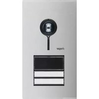
with 0.5 or 1 module 133.5 x 242 x 2 mm
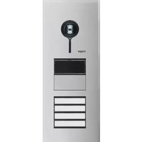
with 0.5 and 1 module 133.5 x 295.8 x 2 mm
with 2 modules 133.5 x 332 x 2 mm
with 0.5 and 2 modules 133.5 x 385.8 x 2 mm
with 3 modules 133.5 x 422 x 2 mm
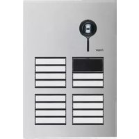
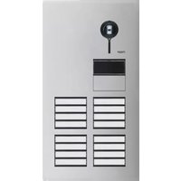
with 2 x 2 modules 225.5 x 332 x 2 mm
with 3 und 2 modules or
with 2 x 3 modules 225.5 x 422 x 2 mm
Accessories (extract)
Flush-mounted housing for door station:
| with 0.5 or 1 module | REW111X |
| with 0.5 and 1 module | REW112X |
| with 2 modules | REW113X |
| with 0.5 and 2 modules | REW114X |
| with 3 modules | REW115X |
| with 2 x 2 modules | REW126X |
| with 3 and 2 modules or with 2 x 3 modules | REW127X |
Surface-mounted housing for door station:
with 0.5 module or 1 module REW211X
with 0.5 module and 1 module REW212X
with 2 modules REW213X
with 0.5 and 2 modules REW214X
with 3 modules REW215X
with 2 x 2 modules REW226X
with 3 and 2 modules or REW227X
with 2 x 3 modules
- Safety instructions
- Function
- Correct use
- Product characteristics
- Operation
- Establish call (ringing)
- Switch-on lights
- Label call push-button
- Lever opening
- Cleaning and care
- Information for electricians
- Installation and electrical connection
- DANGER!
- Bus cables
- Mounting door station
- Safety rope
- Connect door station
- Circuit symbols and elements of the circuit diagrams
- Calling up and changing of system settings
- Setting the values
- Address call push-button automatically RR
- Set individual call push-button address/function Rb
- Display saved error codes EC
- Inserting door station
- Align camera
- Dismantle call push-button module cover
- Open door station
- Exchange module/insert
- Appendix
- Accessories (extract)
Brand : HAGER
Model : REQ608X
Category : Intercom