TVIP91300 - Surveillance Camera ABUS - Free user manual and instructions
Find the device manual for free TVIP91300 ABUS in PDF.
Frequently Asked Questions - TVIP91300 ABUS
User questions about TVIP91300 ABUS
0 question about this device. Answer the ones you know or ask your own.
Ask a new question about this device
Download the instructions for your Surveillance Camera in PDF format for free! Find your manual TVIP91300 - ABUS and take your electronic device back in hand. On this page are published all the documents necessary for the use of your device. TVIP91300 by ABUS.
USER MANUAL TVIP91300 ABUS
natural_image
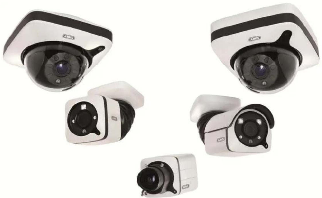
Five different ASIS security cameras shown from different angles (no visible text or labels)D Bedienungsanleitung
UK User manual
FR Manuel utilisateur
NL Gebruikershandleiding
DK Brugerhåndbog
PL Instrukcja obsługi
RU Инструкция по эксплуатации
| D | Diese Bedienungsanleitung enthält wichtige Hinweise zur Inbetriebnahme und Handhabung.Achten Sie hierauf, auch wenn Sie dieses Produkt an Dritte weitergeben.Heben Sie deshalb diese Bedienungsanleitung zum Nachlesen auf!Eine Auflistung der Inhalte finden Sie im Inhaltsverzeichnis mit Angabe der entsprechenden Seitenzahlen auf Seite 6. | DK | Denne manual hører sammen med dette produkt. Den indeholder vigtig information som skal bruges under opsætning og efterfølgende ved service. Dette skal huskes også når produkter gives videre til anden part.Læs derfor denne manual grundigt igennem også for fremtiden.Indholdet kan ses med sideanvisninger kan findes i indekset på side 223. |
| GB | These user manual contains important information for installation and operation. This should be also noted when this product is passed on to a third party.Therefore look after these operating instructions for future reference!A list of contents with the corresponding page number can be found in the index on page 60. | PL | Niniejsza instrukcja obsługi zawiera ważne wskazówki dotyczące uruchamiania i obsługi. Pamiętaj o tym, także przekazując produkt osobie trzeciej. Zachowaj instrukcję do wykorzystania w przyszłości!Wykaz treści znajdziesz w spisie treści z podaniem odpowiednich liczb stron na stronie 276. |
| F | Ce mode d'emploi appartient à de produit. Il contient des recommandations en ce qui concerne sa mise en service et sa manutention. Veuillez en tenir compte et ceci également lorsque vous remettez le produit à des tiers. Conservez ce mode d'emploi afin de pouvoir vous documenter en temps utile!Vous trouverez le récapitulatif des indications du contenu à la table des matières avec mention de la page correspondante à la page 114. | RU | Данная инструкция по эксплуатации содержит важные указания по вводу в эксплуатацию и обращению с продуктом. Примите это во внимание, также при передаче продукта в пользование третьим лицам.По этой причине сохраните данную инструкцию для повторного прочтения!Вся информация отражена в Содержании с указанием соответствующих номеров страниц на Странице 331. |
| NL | Deze gebruiksaanwijzing hoort bij dit product. Er staan belagrijke aanwijzingen in betreffende de ingebruikname en gebruik, ook als u dit product doorgeeft aan derden. Bewaar deze hendeiding zorgvuldig, zodat u deze later nog eens kunt nalezen!U vindt een opsomming van de inhoud in de inhoudsopgave met aanduiding van de paginanummers op pagina 169. | ||
TVIP91XXX / TVIP92XXX
natural_image
Five different ARIS security cameras shown from different angles (no text or labels visible)Version 09/2016
TVIP91XXX
TVIP92XXX
CE
text_image
Technical diagram of a Mitsubishi industrial sensor with numbered components and labeled parts
text_image
Technical diagram of a mechanical device with numbered components and exploded view indicatorsDE
- lens
- Photo sensor
- Microphone
- IR LEDs
- Base plate
- Safety screws
①
- Alarm input and output
- Power supply 12V
- RJ45 connection, PoE capable
- Password reset
- Reset button
- Power LED
- Safety screws
- Breakout point, if lateral cable
routing is desired - 3-axle mount
FR
text_image
Technical diagram of a device with numbered components and labeled parts in Chinese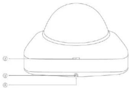
text_image
Technical diagram of a dome-shaped device with numbered labels pointing to its components.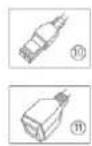
DE
- Reset button
- Password reset
- Status LED for 12 V power supply
- Lens
- Photo sensor
- Fixing screws for camera module
FR
- Recess for removing the cover
- Recess for concealed cable routing
- Breakout point, if lateral cable
routing is desired - 12 V power supply
- RI45 connection, PoE capable
- Recess for removing the cover
- Recess for concealed cable routing
- Breakout point, if lateral cable
routing is desired - 12 V power supply
- RI45 connection, PoE capable
用
text_image
Technical diagram of a mechanical device with numbered parts labeled ①, ②, ③, and ④.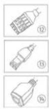
DE
- lens
- Photo sensor
- Status LED
- IR LEDs
- Base plate
- Safety screws
- Sun shield
IFR
- Breakout point, if lateral cable routing is desired
- 3-axle mount
- Password reset
- Reset button
- Alarm input and output
- Power supply 12 VDC
- RI45 connection, PoE capable
1
text_image
Technical diagram of a mechanical device with numbered components and labeled parts in Chinese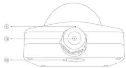
text_image
Technical diagram of a mechanical component with numbered parts labeled 9, 10, and 11

DE
- Reset button
- Password reset
- Status LED for 12 V power supply
- Lens
- Photo sensor
- Fixing screws for camera module
FR
- 12 V power supply
- RJ45 connection, PoE capable
- Recess for removing the cover
- Recess for concealed cable routing
- PG screw connection M25 for lateral cable routing
FR
text_image
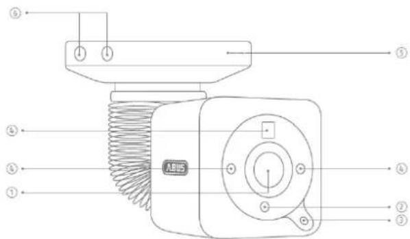
Technical diagram of a mechanical component with numbered parts labeled ① to ⑥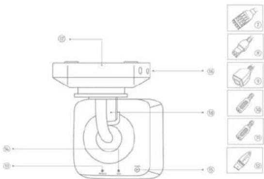
text_image
Technical diagram of a mechanical device with numbered components and exploded view labelsUR
- Lens
- Photo sensor
- Microphone
- IR LEDs
- Base plate
- Safety screws
- Alarm input and output
- Power supply 12V
- RJ45 connection, PoE capable
FR
- Audio input
- Audio output
- Analogue video output for service
- Password reset
- Reset button
- Power LED
- Safety screws
- Breakout point, if lateral cable
routing is desired - 3-axle mount
FR
text_image
Technical diagram of a mechanical device with numbered components for identification
text_image
Technical diagram of a device with numbered labels pointing to components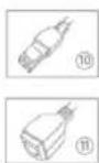
DE
- Reset button / Zoom In
- Password reset / Zoom Out
- Status LED for 12 V power supply
- Lens
- Photo sensor
- Fixing screws for camera module
FIR
- Recess for removing the cover
- Recess for concealed cable routing
- Breakout point, if lateral cable routing is desired
- 12 V power supply
- RJ45 connection, PoE capable
FR
- Lens connection
- ¼ inch thread on top and bottom sides
- Status LED
- Lens base (CS mount)
- Photo sensor
FR
The Ground Truth image displays a single, solid horizontal line. According to Rule 2 (UNDERSCORE & LINE RULES), this is a stylistic or background line, not a placeholder underscore. Therefore, the OCR result must ignore it and output nothing or only meaningful text. The provided OCR content is "____", which consists of four underscores. This is an incorrect interpretation of the line as a placeholder, violating the rule that stylistic lines must be ignored. The OCR has hallucinated placeholder underscores where none exist in the GT. Hence, the OCR result is inconsistent with the Ground Truth.
[Non-Text]
[Non-Text]
[Non-Text]
[Non-Text]
FR
text_image
Technical diagram of an ABUS industrial sensor with numbered components and labeled parts
text_image
Technical diagram of a mechanical device with numbered parts and corresponding component labels in ChineseDE
- Lens
- Photo sensor
- Status LED
- IR LEDS
- Base plate
- Safety screws
- Sun shield
用
- Breakout point, if lateral cable routing is desired
- 3-axle mount
- Password reset
- Reset button
- Alarm input and output
- Power supply 12 VDC
- RJ45 connection, PoE capable
- Audio Input
- Audio output
- Analogue video output for service
四
text_image
Technical diagram of a mechanical device with numbered components and directional arrows indicating assembly or flow.
text_image
Technical diagram of a mechanical component with labeled parts and two inset images showing internal components.DE
- Reset button / Zoom In
- Password reset/Zoom Out
- Status LED for 12 V power supply
- Lens
- Photo sensor
- Fixing screws for camera module
图
- 12 V power supply
B. RJ45 connection, PoE capable - Recess for removing the cover
- Recess for concealed cable routing
- PG screw connection M25 for lateral cable routing
m
natural_image
Two green electrical connectors shown from different angles (no text or symbols visible)text_image
TVIP92700 | Outdoor Dome | H.264 1920X1080 ABUS Install Plugin > There is no Browser plugin installed. You should install the TVIP Plugin to view camera video stream. Continue without Plugin > Image display is slower without plugin.
natural_image
Interior view of a computer lab with electronic equipment and a person at the desk (no visible text or symbols)text_image
http://192.168.0.127/ Outdoor Dome TVIP91700 | Outdoor Dome | H.264 1280x720 ABUSnatural_image
Five different ARUS security cameras shown from different angles (no text or labels visible)Version 09/2016
TVIP91XXX
TVIP92XXX
CE
Dear customer,
Thank you for purchasing this product.
This device complies with the requirements of the applicable EU directives. The declaration of conformity can be obtained from:
To ensure this condition is maintained and that safe operation is guaranteed, it is your obligation to observe this user manual.
Read the entire user manual carefully before putting the product into operation, and pay attention to all operating instructions and safety information.
All company names and product descriptions are trademarks of the corresponding owner. All rights reserved.
If you have any questions, please contact your specialist installation contractor or specialist dealer.

Disclaimer
This user manual has been produced with the greatest of care. Should you discover any missing information or inaccuracies, please let us know about them.
ABUS Security-Center GmbH & Co. KG does not accept any liability for technical and typographical errors, and reserves the right to make changes to the product and user manuals at any time and without prior warning.
ABUS Security-Center GmbH is not liable or responsible for any direct or indirect damage resulting from the installation, performance and use of this product. No forms of guarantee are accepted for the contents of this document.
Important safety information
All guarantee claims are invalid in the event of damage caused by non-compliance with this user manual. We cannot be held liable for resulting damage.

In the event of material or personal damage caused by improper operation or non-compliance with the safety information, we cannot be held liable. All guarantee claims are void in such cases.
Dear customer,
The following safety information and hazard notes are not only intended to protect your health but also to protect the device from damage. Please read the following points carefully:
- There are no components inside the product that require maintenance by the operator. Opening or dismantling the product invalidates the CE certification and guarantee claims/warranty.
- The product may be damaged if it is dropped, even from a low height.
Avoid the following adverse conditions during operation:
- Moisture or excess humidity
- Extreme heat or cold
- Direct sunlight
- Dust or flammable gases, vapours or solvents
• Strong vibrations
• Strong magnetic fields (e.g. next to machines or loudspeakers) - The camera must not be installed on unstable surfaces.
General safety information:
- Do not leave packaging material lying around. Plastic bags, sheeting, polystyrene packaging, etc. can pose a danger to children if played with.
- The video surveillance camera contains small parts which could be swallowed and should be kept out of reach of children for safety reasons.
- Do not insert any objects into the device through the openings.
- Only use replacement devices and accessories that are approved by the manufacturer. Do not connect any non-compatible products.
- Please pay attention to the safety information and user manuals for the other connected devices.
- Check the device for damage before putting it into operation. Do not put the device into operation if you detect any damage.
- Adhere to the operating voltage limits specified in the technical data. Higher voltages could destroy the device and pose a health risk (electric shock).

When installing the device in an existing video surveillance system, ensure that all devices have been disconnected from the mains power circuit and low-voltage circuit.

If in doubt, have a specialist technician carry out assembly, installation and connection of the device. Improper or unprofessional work on the power supply system or domestic installation puts both you and other persons at risk.
Connect the installations so that the mains power circuit and low-voltage circuit always run separately
from each other. They should not be connected at any point or become connected as a result of a malfunction.
Contents
- INTENDED USE....62
- EXPLANATION OF SYMBOLS....62
- SCOPE OF DELIVERY 62
- FEATURES AND FUNCTIONS....63
- DEVICE DESCRIPTION 64
5.1 OVERVIEW – MODEL NUMBERS 64
5.2 UNPACKING THE DEVICE 64
5.3 OVERVIEW OF CONNECTIONS, CONTROL ELEMENTS, FRONT/BACK 65
- INSTALLATION 74
6.2 LAYING THE CABLES 74
6.3 POWER SUPPLY....75
6.4 ATTACHING THE NETWORK CABLE 76
6.5 ALIGNING THE CAMERA 76
6.6 ZOOM AND FOCUS SETTINGS....76
6.7 ATTACHING THE OPTIONAL CONNECTING CABLE FOR TVIP9X300 AND TVIP9X700.... 77
6.8 SWITCHING INPUT AND SWITCHING OUTPUT 77
6.9 STATUS INDICATORS....78
6.10 CONNECTION INSTRUCTIONS FOR AUDIO INPUT/OUTPUT (TVIP92XXX) 78
6.11 RESTORING FACTORY SETTINGS (RESET)....79
6.12 CHANGING THE DOME 79
- INITIAL START-UP 80
7.1 USING THE ABUS IP INSTALLER FOR CAMERA SEARCH 80
7.2 ACCESSING THE NETWORK CAMERA USING A WEB BROWSER 81
7.2.1 GENERAL INSTRUCTIONS FOR USING THE SETTINGS PAGES....81
7.3 INSTALLING A VIDEO PLUGIN 81
7.4 HOMEPAGE (LOGIN PAGE) 83
7.5 USER ACCOUNTS AND PASSWORDS 84
7.6 LINKING UP THE CAMERA WITH ABUS VMS/ABUS VMS EXPRESS.... 85
7.6 LINKING UP THE CAMERA WITH ABUS NVR/ABUS HYBRID DVR 85
7.8 LINKING UP THE CAMERA TO IPCAM 85
-
USER MENU "USER" 86
-
VIEW AND CONFIGURATION MENU USER "MASTER" 88
9.1 ADDING USERS....90
9.2 VIDEO STREAM SETTINGS.... 91
9.2 DEACTIVATE/ACTIVATE INSTALLER ACCESS 91
9.3 DISPLAYING/DOWNLOADING VIDEO FROM THE INTERNAL MEMORY 92
- VIEW AND CONFIGURATION MENUS USER "INSTALLER" 93
10.1 LIVE VIEW 93
10.2 INFO PAGE 95
10.3 SETUP WIZARD 96
10.4 ADVANCED CAMERA SETTINGS 96
10.4.1 VIDEO 96
10.4.1.1 GENERAL 96
10.4.1.2 DAY PROFILE 96
10.4.1.3 NIGHT PROFILE 97
10.4.1.4 DAY/NIGHT SWITCHING 97
10.4.1.5 PRIVACY MASKING....97
10.4.1.6 VIDEO STREAM SETTINGS 98
10.4.1.7 NETWORK LOSS RECORDING.... 100
10.4.2 NETWORK.... 101
10.4.2.1 IPv4 SETTINGS 101
10.4.2.2 PORTS.... 101
10.4.2.3 DDNS 101
10.4.2.4 HTTPS 102
10.4.2.5 SMTP/EMAIL 102
10.4.3 OVERLAY TEXT.... 102
10.4.4 DATE/TIME 102
10.4.5 SYSTEM.... 103
10.4.5.1 GENERAL.... 103
10.4.5.2 FIRMWARE/RESET 103
10.4.5.3 LOG FILE.... 104
10.4.6 MOTION DETECTION 104
10.4.7 ALARM MANAGER 104
10.4.8 AUDIO.... 105
10.4.9 INSTALLER 105
10.4.10 SERVICE 105
- MAINTENANCE AND CLEANING.... 107
11.1 FUNCTION TEST.... 107
11.2 CLEANING.... 107
- DISPOSAL 107
- TECHNICAL DATA.... 108
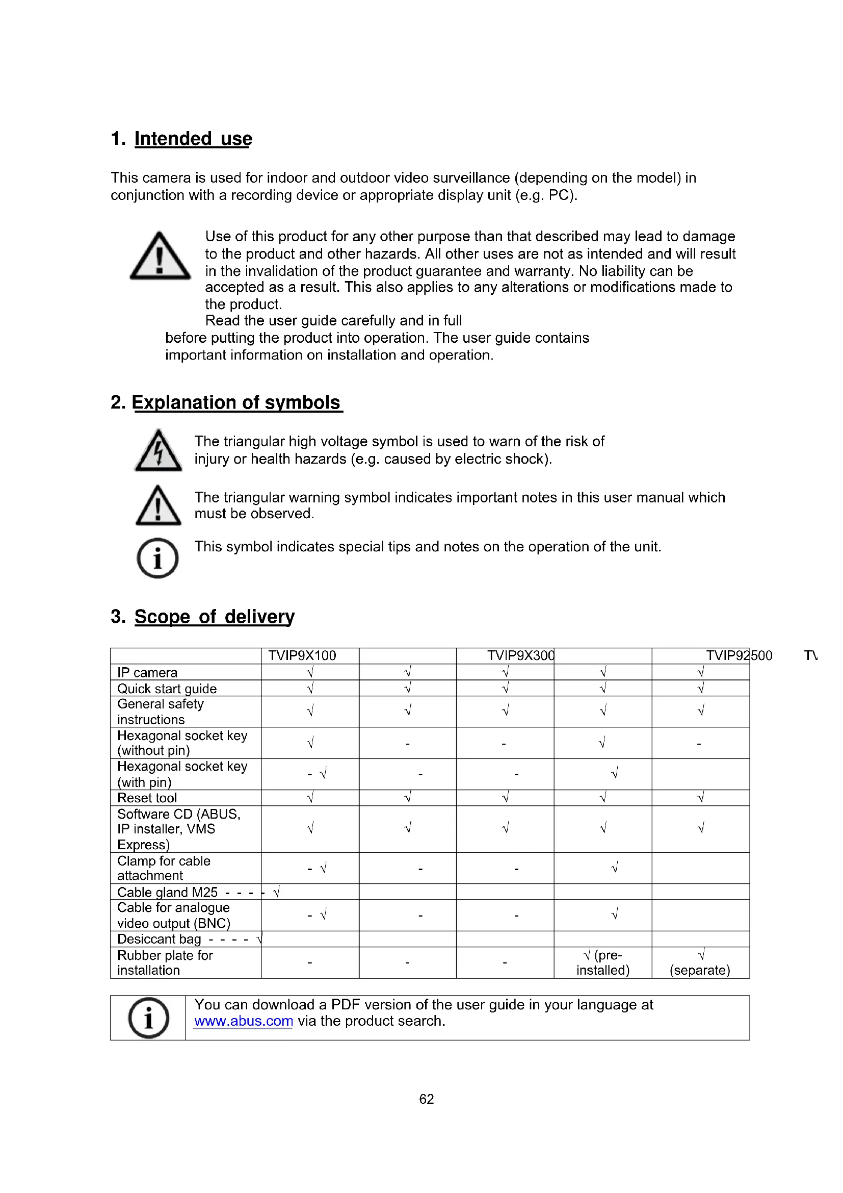
1. Intended use
This camera is used for indoor and outdoor video surveillance (depending on the model) in conjunction with a recording device or appropriate display unit (e.g. PC).

Use of this product for any other purpose than that described may lead to damage to the product and other hazards. All other uses are not as intended and will result in the invalidation of the product guarantee and warranty. No liability can be accepted as a result. This also applies to any alterations or modifications made to the product.
Read the user guide carefully and in full before putting the product into operation. The user guide contains important information on installation and operation.
2. Explanation of symbols
The triangular high voltage symbol is used to warn of the risk of injury or health hazards (e.g. caused by electric shock).

The triangular warning symbol indicates important notes in this user manual which must be observed.

This symbol indicates special tips and notes on the operation of the unit.
3. Scope of delivery
| TVIP9X100 | TVIP9X300 | TVIP92500 | |||
| IP camera | √ | √ | √ | √ | √ |
| Quick start guide | √ | √ | √ | √ | √ |
| General safety instructions | √ | √ | √ | √ | √ |
| Hexagonal socket key (without pin) | √ | - | - | √ | - |
| Hexagonal socket key (with pin) | - √ | - | - | √ | |
| Reset tool | √ | √ | √ | √ | √ |
| Software CD (ABUS, IP installer, VMS Express) | √ | √ | √ | √ | √ |
| Clamp for cable attachment | - √ | - | - | √ | |
| Cable gland M25 - - - - √ | |||||
| Cable for analogue video output (BNC) | - √ | - | - | √ | |
| Desiccant bag - - - - √ | |||||
| Rubber plate for installation | - | - | - | √ (pre-installed) | √(separate) |

You can download a PDF version of the user guide in your language at www.abus.com via the product search.
4. Features and functions
TVIP91XXX
• HD 720p resolution: 1280 x 720 @ 25 fps
- 3.6 mm fixed lens
- Day/night switching with electromechanical IR blocking filter (ICR)
- WDR function (46 dB) to compensate for image contrasts
- IR LEDs for night vision (TVIP91100 and TVIP91600 only)
- 16 GB internal memory for recording in the event of a power failure (TVIP91300 and TVIP91700 only)
• Power over Ethernet (PoE)
• ONVIF profile S compatible
TVIP92XXX
• Full HD 1080p resolution: 1920 x 1080 @ 25 fps
- Sony Xarina DSP and Sony Exmore image sensor
- Tamron Motor Vario lens 3–9 mm (TVIP92100, TVIP92300, TVIP92610 and TVIP92700 only) or 9–22 mm (TVIP92600)
• 16 GB internal memory for recording in the event of a power failure
- Day/night switching with electromechanical IR blocking filter (ICR)
- IR LEDs with variable intensity (TVIP92100, TVIP92600 and TVIP92610 only)
- WDR function to compensate for high image contrasts
• Power over Ethernet (PoE)
- ONVIF-compatible
5. Device description
5.1 Overview - Model numbers
| Model number | TVIP91100 | TVIP91300 | TVIP91600 | TVIP91700 |
| Resolution | 720p | 720p | 720p | 720p |
| DWDR/WDR | DWDR,46 dB | DWDR,46 dB | DWDR,46 dB | DWDR,46 dB |
| 2D DNR/3D DNR | √ | √ | √ | √ |
| Lens | Fixed-lens,3.6 mm | Fixed-lens,3.6 mm | Fixed-lens,3.6 mm | Fixed-lens,3.6 mm |
| Operating voltage 12 V DC 12 V DC | 12 V DC 12 V DC | |||
| PoE | IEEE802.3af | IEEE802.3af | IEEE802.3af | IEEE802.3af |
| Model number TVIP92100 TVIP92300 | TVIP92500 | TVIP92600 | TVIP92700 | ||
| Resolution | 1080p | 1080p | 1080p | 1080p | 1080p |
| DWDR/WDR | WDR, >100 dB | WDR, >100 dB | WDR, >100 dB | WDR, >100 dB | WDR, >100 dB |
| 2D DNR/3D DNR | √ | √ | √ | √ | √ |
| Lens | Motor 3–9 mm | Motor zoom, 3–9 mm | - | Motor zoom, 9–22 mm | Motor zoom, 3–9 mm |
| Operating voltage 12 V DC 12 V DC | 12 V DC 12 V DC 12 V DC | ||||
| PoE | IEEE 802.3af | IEEE 802.3af | IEEE 802.3af | IEEE 802.3af | IEEE 802.3af |
| Model number TVIP92610 | |
| Resolution | 1080p |
| DWDR/WDR | WDR, >100 dB |
| 2D DNR/3D DNR √ | |
| Lens | Motor 3-9 mm |
| Operating voltage 12 V DC | |
| PoE | IEEE 802.3af |
zoom,
5.2 Unpacking the device
Handle the device with extreme care when unpacking it.

If the original packaging has been damaged, inspect the device first. If the device shows signs of damage, return it in the original packaging and inform the delivery service.
5.3 Overview of connections, control elements, front/back
TVIP91100
text_image
Technical diagram of a Mitsubishi industrial sensor with numbered components and labeled parts
text_image
Technical diagram of a mechanical device with numbered components and exploded view indicatorsDE
- lens
- Photo sensor
- Microphone
- IR LEDs
- Base plate
- Safety screws
①
- Alarm input and output
- Power supply 12V
- RJ45 connection, PoE capable
- Password reset
- Reset button
- Power LED
- Safety screws
- Breakout point, if lateral cable
routing is desired - 3-axle mount
FR
text_image
Technical diagram of a device with numbered components and labeled parts in Chinese
text_image
Technical diagram of a dome-shaped device with numbered labels pointing to its components.
B
-
Reset button
-
Password reset
-
Status LED for 12 V power supply
-
Lens
-
Photo sensor
-
Fixing screws for camera module
EIR
-
Recess for removing the cover
-
Recess for concealed cable routing
-
Breakout point, if lateral cable
routing is desired
-
12 V power supply
-
RI45 connection, PoE capable
FR
The Ground Truth image displays a single, solid horizontal line. According to Rule 2 (UNDERSCORE & LINE RULES), this is a stylistic or background line, not a placeholder underscore. Therefore, the OCR result must ignore it and output nothing or only meaningful text. The provided OCR content is "\_\_\_\_", which consists of four underscores. This is an incorrect interpretation of the line as a placeholder, violating the rule that stylistic lines must be ignored. The OCR has hallucinated placeholder underscores where none exist in the GT. Hence, the OCR result is inconsistent with the Ground Truth.
-
-
[Non-Text]
[Non-Text]
[Non-Text]
[Non-Text]
[Non-Text]
[Non-Text]
[Non-Text]
[Non-Text]
[Non-Text]
[Non-Text]
[Non-Text]
[Non-Text]
-
m = 311
The Ground Truth image displays a single, solid horizontal line. According to Rule 2 (UNDERSCORE & LINE RULES), this is a stylistic or background line, not a placeholder underscore. Therefore, the OCR result must ignore it and output nothing or only meaningful text. The provided OCR content is "\_\_\_\_", which consists of four underscores. This is an incorrect interpretation of the line as a placeholder, violating the rule that stylistic lines must be ignored. The OCR has hallucinated placeholder underscores where none should exist in the GT. This adheres to the strict requirement to ignore such lines.
[Non-Text]
[Non-Text]
[Non-Text]
[Non-Text]
[Non-Text]
[Non-Text]
[Non-Text]
[Non-Text]
[Non-Text]
[Non-Text]
[Non-Text]
[Non-Text]
-
The Ground Truth image displays a single, solid horizontal line. According to Rule 2 (UNDERSCORE & LINE RULES), this is a stylistic or background line, not a placeholder underscore. Therefore, the OCR result must ignore it and output nothing or only meaningful text. The provided OCR content is "\_\_\_\_", which consists of four underscores. This is an incorrect interpretation of the line as a placeholder, violating the rule that stylistic lines must be ignored. The OCR has hallucinated placeholder underscores where none should exist in the GT. This adheres to the strict requirement to ignore such lines.
[Non-Text]
[Non-Text]
[Non-Text]
[Non-Text]
[Non-Text]
[Non-Text]
[Non-Text]
[Non-Text]
[Non-Text]
[Non-Text]
[Non-Text]
-
m = 311
The Ground Truth image displays a single, solid horizontal line. According to Rule 2 (UNDERSCORE & LINE RULES), this is a stylistic or background line, not a placeholder underscore. Therefore, the OCR result must ignore it and output nothing or only meaningful text. The provided OCR content is "\_\_\_\_", which consists of four underscores. This is an incorrect interpretation of the line as a placeholder, violating the rule that stylistic lines must be ignored. The OCR has hallucinated placeholder underscores where none should exist in the GT. This adheres to the strict requirement to ignore such lines.
[Non-Text]
[Non-Text]
![ABUS TVIP91300 - [Non-Text] - 1](/content/2026/02/412729/images/52666b3a37c2edd692d68dce7bb03d1970962b73b9752a9bd643a4ee297f9960.jpg)
text_image
Technical diagram of an ADRUS industrial sensor with numbered components and labeled parts![ABUS TVIP91300 - [Non-Text] - 2](/content/2026/02/412729/images/a8875079c9803dbc41828450f49a646fa5d608ed96edabcc7b47734302be1f33.jpg)
text_image
Technical diagram of a mechanical device with numbered components and exploded view labelsDH
- lens
- Photo sensor
- Status LED
- IR LEDs
- Base plate
- Safety screws
- Sun shield
FR
- Breakout point, if lateral cable routing is desired
- 3-axle mount
- Password reset
- Reset button
- Alarm input and output
- Power supply 12 VDC
- RI45 connection, PoE capable
PR
①
text_image
Technical diagram of a mechanical device with numbered components and labeled parts in Chinese
text_image
Technical diagram of a mechanical component with numbered parts labeled ⑨, ⑪, and ⑯.

DE
- Reset button
- Password reset
- Status LED for 12 V power supply
- Lens
- Photo sensor
- Fixing screws for camera module
FR
- 12 V power supply
- RJ45 connection, PoE capable
- Recess for removing the cover
- Recess for concealed cable routing
- PG screw connection M25 for lateral cable routing
FR
text_image
Technical diagram of a mechanical component with numbered parts labeled ① to ⑥
text_image
Technical diagram of a mechanical device with numbered components and exploded view labelsUR
- Lens
- Photo sensor
- Microphone
- IR LEDs
- Base plate
- Safety screws
- Alarm input and output
- Power supply 12V
- RJ45 connection, PoE capable
FR
[Non-Text]
[Non-Text]
[Non-Text]
[Non-Text]
[Non-Text]
[Non-Text]
[Non-Text]
[Non-Text]
[Non-Text]
FR
- (1)
- [Non-Text]
18.
PL
text_image
Technical diagram of a mechanical device with numbered components for identification
text_image
Technical diagram of a dome-shaped device with numbered components and corresponding close-up images labeled ⑩ and ⑪.DE
- Reset button / Zoom In
- Password reset / Zoom Out
- Status LED for 12 V power supply
- Lens
- Photo sensor
- Fixing screws for camera module
FIR
- Recess for removing the cover
- Recess for concealed cable routing
- Breakout point, if lateral cable routing is desired
- 12 V power supply
- RJ45 connection, PoE capable
FR
- Lens connection
- ¼ inch thread on top
and bottom sides - Status LED
- Lens base (CS mount)
- Photo sensor
FR
The Ground Truth image displays a single, solid horizontal line. According to Rule 2 (UNDERSCORE & LINE RULES), this is a stylistic or background line, not a placeholder underscore. Therefore, the OCR result must ignore it and output nothing or only meaningful text. The provided OCR content is "____", which consists of four underscores. This is an incorrect interpretation of the line as a placeholder, violating the rule that stylistic lines must be ignored. The OCR has hallucinated placeholder underscores where none exist in the GT. Hence, the OCR result is inconsistent with the Ground Truth.
[Non-Text]
[Non-Text]
[Non-Text]
[Non-Text]
FR
text_image
Technical diagram of an ABUS industrial sensor with numbered components and labeled parts
text_image
Technical diagram of a mechanical device with numbered parts and corresponding component labels in ChineseDE
- Lens
- Phot
- Status LED
- IR LEDS
- Base plate
- Safety screws
- Sun shield
用
- Breakout point, if lateral cable routing is desired
- 3-axle mount
- Password reset
- Reset button
- Alarm input and output
- Power supply 12 VDC
- RJ45 connection, PoE capable
- Audio Input
- Audio output
- Analogue video output for service
四
⑪
text_image
Technical diagram of a mechanical device with numbered components and directional arrows indicating assembly or flow.
text_image
Technical diagram of a mechanical component with labeled parts and two inset images showing internal components.DE
- Reset button / Zoom In
- Password reset / Zoom Out
- Status LED for 12 V power supply
- Lens
- Photo sensor
- Fixing screws for camera module
图
- 12 V power supply
- R045 connection, PoE capable
- Recess for removing the cover
- Recess for concealed cable routing
- PG screw connection M25 for lateral cable routing
m
Instructions for how to mount the camera are described in the quickstart guide for the relevant IP camera TVIP9XXXX.

When mounting the dome cameras TVIP91700 and TVIP92700 please make sure that the desiccant bag supplied is placed inside the camera before placing on the dome. The bag must be placed close to the base plate. The bag must not be in the field of view of the lens. The bag must not be placed directly behind the lens or the camera board.
6.2 Laying the cables
You must pay attention to the following instructions when laying the cables:
TVIP91100/TVIP92100
A break-out panel for feeding the cable is located on the base plate for laying the cables at the side. Use pliers to remove the break-out panel. Use a file to smooth out the edges of the break-out panel.
TVIP91300/TVIP92300
A break-out panel for feeding the cable is provided for laying the cables at the side. Use a flat, narrow screwdriver to remove the break-out panel from the plastic.

These cameras are equipped ex works with a short connecting cable for networking (RJ45), power supply (barrel connector) and analogue video output. Making the connection is possible from inside the camera. In the most simple case, a network cable with Power over Ethernet power supply is all that's needed to operate the camera.
If the functions switching input, switching output or audio input/output (TVIP92300 only) are needed, you must install an extended connecting cable (for TVIP91300: TVAC40700; for TVIP92300: TVAC40720).
TVIP92500
When laying the cable, ensure that none of the plug connections is subject to mechanical tension. Furthermore, cables must be fixed in such a way as to prevent the plug from being bent or snapped off.
TVIP91600/TVIP92600 / TVIP92610
A break-out panel for feeding the cable is located on the base plate for laying the cables at the side. Use pliers to remove the break-out panel. Use a file to smooth out the edges of the break-out panel.
For this type of camera, the cable is intended to be laid at the side or concealed. There are openings at the side and on the base for this. The unused opening is sealed using a blind plug. For installation the supplied cable gland must be used (for the side and base) in accordance with protection class IP66. When using the optional wall bracket (TVAC31310), the cable gland may be omitted, as the wall bracket panel and dome camera have been manufactured to fit together tightly.

These cameras are equipped ex works with a short connecting cable for networking (RJ45), power supply (barrel connector) and analogue video output. Making the connection is possible from inside the camera. In the most simple case, a network cable with Power over Ethernet power supply is all that's needed to operate the camera.
If the functions switching input, switching output or audio input/output (TVIP92300 only) are needed, you must install an extended connecting cable (for TVIP91300: TVAC40700; for TVIP92300: TVAC40720).
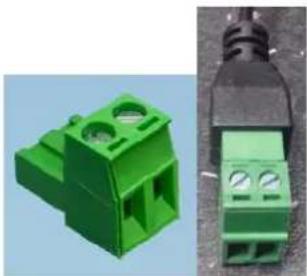
6.3 Power supply
Before starting installation, ensure that the power supply voltage and the rated voltage of the camera are identical.
natural_image
Two green plastic electrical connectors shown from different angles (no text or symbols visible)DC power supply, 12 V
TVIP9XXXX
The cameras have a 12 V DC power supply. Ensure correct polarity when connecting. The polarity is indicated with "+" and "-".
In addition, all cameras have Power over Ethernet (PoE) to supply the camera directly via the network cable.

If the camera has the function "Record during network failure" and this function is to be used, it's necessary to supply the camera via the 12 V DC terminal (do not use PoE).

When using PoE, you must pay attention to the power budget of the network switch. Make sure that each network port provides the maximum power for the standard (15.4 watt per network port). If the network switch distributes the power dynamically via all ports, it may cause power shortages.
6.4 Attaching the network cable
The maximum network cable (CAT7) length from the camera to the nearest active network point (e.g. network switch) should not exceed 100 metres.
6.5 Aligning the camera
Instructions for how to align the camera are given in the quickstart guide for the relevant IP camera TVIP9XXXX.
6.6 Zoom and focus settings
TVIP91100/TVIP91300/TVIP91600/TVIP91700
The cameras have a built-in fix lens. The focal length is dependent on the lens and the focus is already factory-set. It is not possible to change the angle of view or the focus.
TVIP92100/TVIP92300/TVIP92600/TVIP92610/TVIP92700
The cameras have a built-in Motor Vario zoom lens. It is possible to change the zoom factor or adapt the focus via the camera's web interface ("installer" access).
The zoom factor can be changed in stages, whereas the focus is automatically set for each of these zoom factors. It's possible to change the focus of each zoom factor via the camera's web interface ("installer" access). The change will be saved to the camera (over button "SAVE" on main page of "installer" access). When the camera undergoes a factory reset, the factory-set zoom/focus relationship is reset too.
It is also possible to operate the zoom function using the two reset buttons. You can find a more detailed description of this under point 6.10 "Restoring factory settings (reset)".
TVIP92500
Settings for zoom and focus are made manually in the lens to be installed (lens is not included in the scope of delivery).
6.7 Attaching the optional connecting cable for TVIP9X300 and TVIP9X700
Using the optional connecting cables TVAC40700, TVAC40710, TVAC40720 and TVAC40730, suitable dome cameras can gain the following additional interfaces:
| TVAC40700 TVAC40710 TVAC40720 TVAC40730 | ||||
| Suitable for TVIP91300 TVIP91700 | TVIP92300 TVIP92700 | |||
| Audio input, 3.5 mm stereo plug | - | - | ||
| Audio output, 3.5 mm stereo plug | - | - | ||
| 1 x switching input | ||||
| 1 x switching output | ||||
| Video output, BNC 1 Vss | - | - | ||
6.8 Switching input and switching output
| The maximum load values must be observed, otherwise the camera may be damaged irreparably. |
| Name Connection instructions | ||
| Switching input DI+ 5 V DC ~ 12 V | DC max. 50 mA | |
| DI- | ||
| Switching output | DO+ Max. 60 V DC/AC, max. 400 mA, Ron=1.4 Ohm (photo relay) | |
| DO- | ||
6.9 Status indicators
TVIP91100/TVIP91300/TVIP91600/TVIP91700
The only status indicator available is the supply voltage display.
TVIP92100/TVIP92300/TVIP92500/TVIP92600/TVIP92610/TVIP92700
| Display LED Function | |
| LED to display supply voltage (green) | If the LED is active and uninterrupted, the supply voltage is correct and available. |
| Status LED (blue) a) LED flashes 1/s-> Camera is starting up, booting processb) LED deactivated (LED displaying supply voltage is permanently active)-> Camera start-up process has finished, functional status normalc) LED permanently on-> Fault. Network connection not possible.If it is not possible to access the camera, try to reset the camera using the reset button. | |
6.10 Connection instructions for audio input/output (TVIP92XXX)
Information will follow up!
6.11 Restoring factory settings (reset)
Resetting the password for "master" access
- Turn off the camera.
- Press and hold the "PW reset" button on the camera.
- Now connect the power supply to the camera (using 2-pin power supply or Power over Ethernet) and hold down the "PW reset" button for a further 60 seconds.
Reset all camera settings
- Turn off the camera.
- Press and hold the "Reset" button on the camera.
- Now connect the power supply to the camera (using 2-pin power supply or Power over Ethernet) and hold down the "Reset" button for a further 60 seconds.
Further use of the reset buttons
This function only applies for TVIP92100, TVIP92300, TVIP926X0 and TVIP92700.
If the camera has finished its start-up process (status LED inactive, LED for power supply active), the two reset buttons preserve the function for zooming in and zooming out.
6.12 Changing the dome
TVIP91300/TVIP92300/TVIP91700/TVIP92700
If required, there is a tinted dome available for the IP dome cameras specified (ABUS item number TVAC31065).
The dome is installed as follows:
- Remove the dome from the camera by loosening the four fixing screws (dome with dome ring).
- Remove the remove fixing screws on the underside of the dome.
- Remove the dome from the dome ring.
- Insert the tinted dome into the dome ring.
- Place the fixing ring on the underside of the dome ring and screw in the four fixing screws.
7. Initial start-up
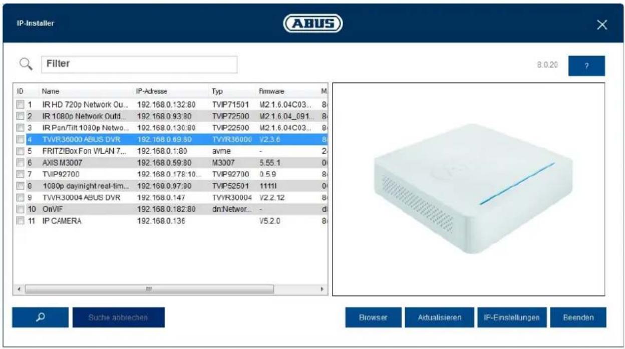
7.1 Using the ABUS IP Installer for camera search
Install and start up the ABUS IP Installer using the enclosed software CD (or alternatively using the ABUS website www.abus.com, available for each respective product).
The IP camera should now appear in the selection list without the relevant IP address for the target network, where appropriate. The IP settings for the camera can be changed using the IP installer.
The language preference for the camera can also be changed using the ABUS IP installer. This will change the language preference for the master and installer users at the same time (for an explanation of master/installer, see chapter "User accounts and passwords"). Individual language preferences can be amended in the settings menus for master and installer.

Please be aware, that the language preference for the camera homepage is set automatically depending on the operating system language preference. If this language is not available in the camera, the homepage will be shown in English.
Using the "Browser" button, a previously selected camera can be opened directly in the internet browser (the default browser for Windows will be used).
text_image
IP-Installer ABUS Filter 8.0.20 ? ID Name IP-Adresse Typ Firmware M 1 IR HD 720p Network Ou... 192.168 0.132:80 TVIP71501 M2 1.6.04C03... 8 2 IR 1080p Network Outd... 192.168 0.93:80 TVIP72500 M2 1.6.04_091... 8 3 IR Pan/Tilt 1080p Netwo... 192.168 0.130:80 TVIP22500 M2 1.6.04C03... 8 4 TVVR36000 ABUS DVR 192.168 0.69:80 TVVR36000 V2.3.6 8 5 FRITZ!Box Fon WLAN 7... 192.168 0.1:80 avme - 2 6 AXIS M3007 192.168 0.59:80 M3007 5.55.1 0 7 TVIP92700 192.168 0.178:10... TVIP92700 0.5.9 8 8 1000p day/night real-tim... 192.168 0.97:80 TVIP52501 1111I 0 9 TVVR30004 ABUS DVR 192.168 0.147 TVVR30004 V2.2.12 8 10 OnVIF 192.168 0.182:80 dnNetwor... - d 11 IP CAMERA 192.168 0.136 V5.2.0 8 Suche abblechen Browser Aktualisieren IP-Einstellungen Reenden7.2 Accessing the network camera using a web browser
Enter the camera IP address into the address bar in the browser (if a different HTTP Port is used in Internet Explorer you must also enter "http://" before the IP address.)

text_image
http://192.168.0.182/ IP_Camera7.2.1 General instructions for using the settings pages
| Functional element Description | |
 | Save settings that have been made on the page.Please note that the new settings will only apply after the save button has been pressed. |
  | Function activated |
 DHCP DHCP | Function deactivated |
  | List selection |
 | Input field |
| [30TK] [TXSA] max. | Slide control |
7.3 Installing a video plugin
Internet Explorer
A plugin called ActiveX is used for displaying videos in Internet Explorer. This plugin must be installed in the browser. You will be asked to confirm the installation directly after entering your username and password (default: master/master).

If the ActiveX Plugin installation is blocked by Internet Explorer, you will need to reduce your security settings to install/initialise ActiveX.
Google Chrome
A plugin is used for displaying videos in the Google Chrome browser. You will be asked to confirm the installation directly after entering your username and password (default: master/master or installer/installer).

text_image
TVIP92700 | Outdoor Dome | H.264 1920X1080 ABUS Install Plugin > There is no Browser plugin installed. You should install the TVIP Plugin to view camera video stream. Continue without Plugin > Image display is slower without plugin.
Google Chrome users please note: the video plugin is only supported by the Windows version of the Google Chrome browser.
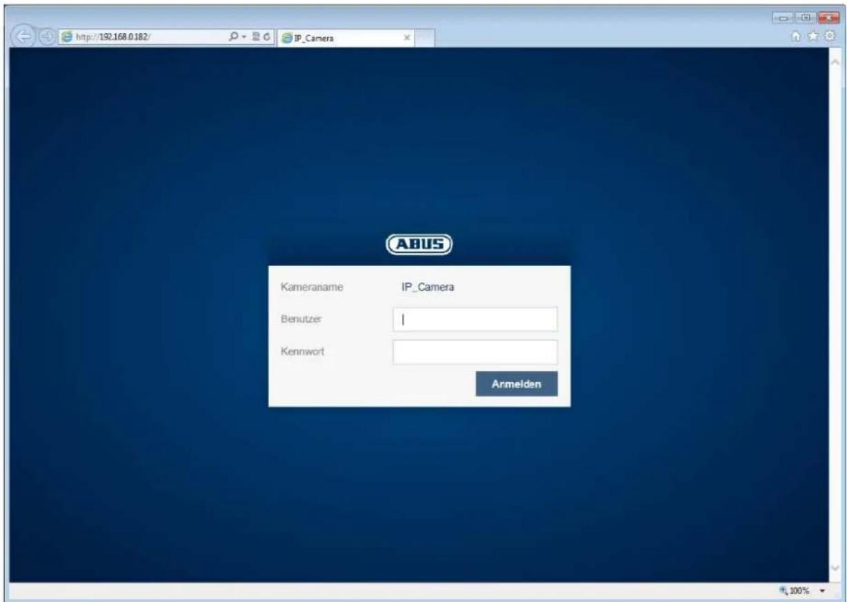
7.4 Homepage (login page)
After entering the IP address in the browser's address bar and opening up the page, the home page will appear in the language set in the Internet Explorer options (Windows setting).
Each respective user account (installer, master or user) can set their language individually. For example, the settings pages can be set to English for the "installer" account and German for the "master" account.
The following languages are supported: German, English, French, Dutch, Danish, Polish, Spanish, Portuguese, Swedish, Italian and Russian.
If a language is not supported, the website will be displayed in English.
text_image
http://192.168.0.182/ IP_Camera ABUS Kameraname IP_Camera Benutzer | Kennwort Armelden7.5 User accounts and passwords
Overview of the types of user with the username descriptions, the default passwords and corresponding privileges.
| User types | Username | Default password | Privileges | |
| Installer | Installer | Video display on web browserInstant imageLocal video recording on PCControl microphone/Speaker (optional)Full screen mode in browserZoom/Focus setting (if available)System overviewImage settings for day and night modeVideo streaming quality settingsSetting for network loss recordingDay/night switchingPrivacy maskingIP address settingsSetting for connection portsDDNS settingsHTTPS settingsSMTP settingsDisplayed textDate/TimeExport/Import/RestoreFirmware update/RestartLog fileMotion detection settingsAlarm management (email/switch output)Audio parameter | ||
| master | master | Video display on web browserInstant imageLocal video recording on PCControl microphone/Speaker (optional)Full screen mode in browserAdd, change or delete usersBlock and unblock "installer" accessPlayback of recordings from the internal memory (after network failure) | ||
| user | assigned and modified by master> | Video display on web browserInstant imageLocal video recording on PCControl microphone/Speaker (optional)Full screen mode in browser | ||
| Recording | NVR | Access to video stream for recordingsSetting the video quality of the video stream for recordings | ||
| Mobile device mobile | mobile | |||
7.6 Linking up the camera with ABUS VMS/ABUS VMS Express
The following information is required to link up the camera with ABUS VMS/ABUS VMS Express:
• IP address/domain name
- http port (default 80)
- rtsp port (default 554, can be changed, is detected automatically)
- Username: NVR
- Password: NVR (can be modified via the installer settings)
7.6 Linking up the camera with ABUS NVR/ABUS Hybrid DVR
The following information is required to link up the camera with ABUS NVR/ABUS Hybrid DVR:
• IP address/domain name
- http port (default 80)
- rtsp port (default 554, may not be changed)
- Username: NVR
- Password: NVR (can be modified via the installer settings)
7.8 Linking up the camera to IPCam
The following information is required to link up the camera with IPCam:
- IP address/domain name
- http port (default 80)
- rtsp port (default 554)
- Username: mobile
- Password: mobile (can be modified in the installer settings)
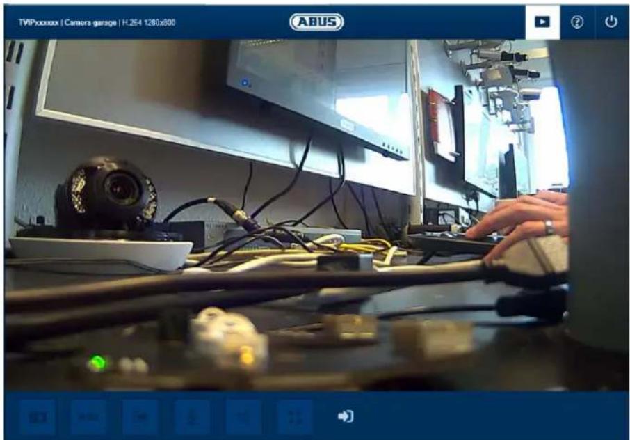
8. User menu "user"
| Button/display on screen Function | ||
| TVIPxxxxxx | Camera garage | H.264 1280x800 | Information bar | |
 | Live display | |
 | Help page | |
 | Log out as user | |
natural_image
Interior view of a computer lab with electronic equipment and a person working at a desk (no visible text or symbols)| Button/display on screen | Function | |
 | Instant image functionThis function saves an instant image from the current video stream in JPEG format. The picture is stored in the following folder:C:/Benutzer/ | |
 | Video functionThis function saves a video from the current video stream in AVI format.The video is stored in the following folder:C:/Benutzer/ Eigene Videos | |
 | Activate switching outputThis button can be used to manually activate or deactivate the switching output (e.g. door opener function). | |
 | Muting the microphone (if available)This button can be used to deactivate the microphone in the camera (TVIP91100) or the microphone in the optional audio input (TVIP92xxx). | |
 | Muting the speaker (if available)This button can be used to deactivate the speaker in the optional audio output (TVIP92xxx). | |
 | Full screen modeSwitching the video picture on the monitor to full screen mode (you can also do this by double clicking within the video frame). You can exit full screen mode by double clicking within the video frame again or pressing the ESC button. | |
 | Status display switching inputThis symbol displays the activation status of the switching input. | |
9. View and configuration menu user "master"

text_image
http://192.168.0.178/camera.html#Zoom TVIP92700 | Outdoor Domo | H.264 1920X1080 ABUS IP-Kamera Webserte(example image of TVIP92700)
| Button/display on screen | Function |
 | Instant image functionThis function saves an instant image from the current video stream in JPEG format. The picture is stored in the following folder:C:/Benutzer//Eigene Bilder |
 | Video functionThis function saves a video from the current video stream in AVI format.The video is stored in the following folder:C:/Benutzer//Eigene Videos |
 | Activate switching outputThis button can be used to manually activate or deactivate the switching output (e.g. door opener function). |
 | Muting the microphone (if available)This button can be used to deactivate the microphone in the camera (TVIP91100) or the microphone in the optional audio input (TVIP92xxx). | |
| Muting the speaker (if available)This button can be used to deactivate the speaker in the optional audio output (TVIP92xxx). | ||
 | Full screen modeSwitching the video picture on the monitor to full screen mode (you can also do this by double clicking within the video frame). You can exit full screen mode by double clicking within the video frame again or pressing the ESC button. | |
 | Status display switching inputThis symbol displays the activation status of the switching input. | |
| Live view page for "master" user | ||
 | Information page with explanations of what the buttons do. | |
| Settings page for "master" user. | ||
 | Log out as user. Afterwards the login page is displayed again. |
9.1 Adding users
text_image
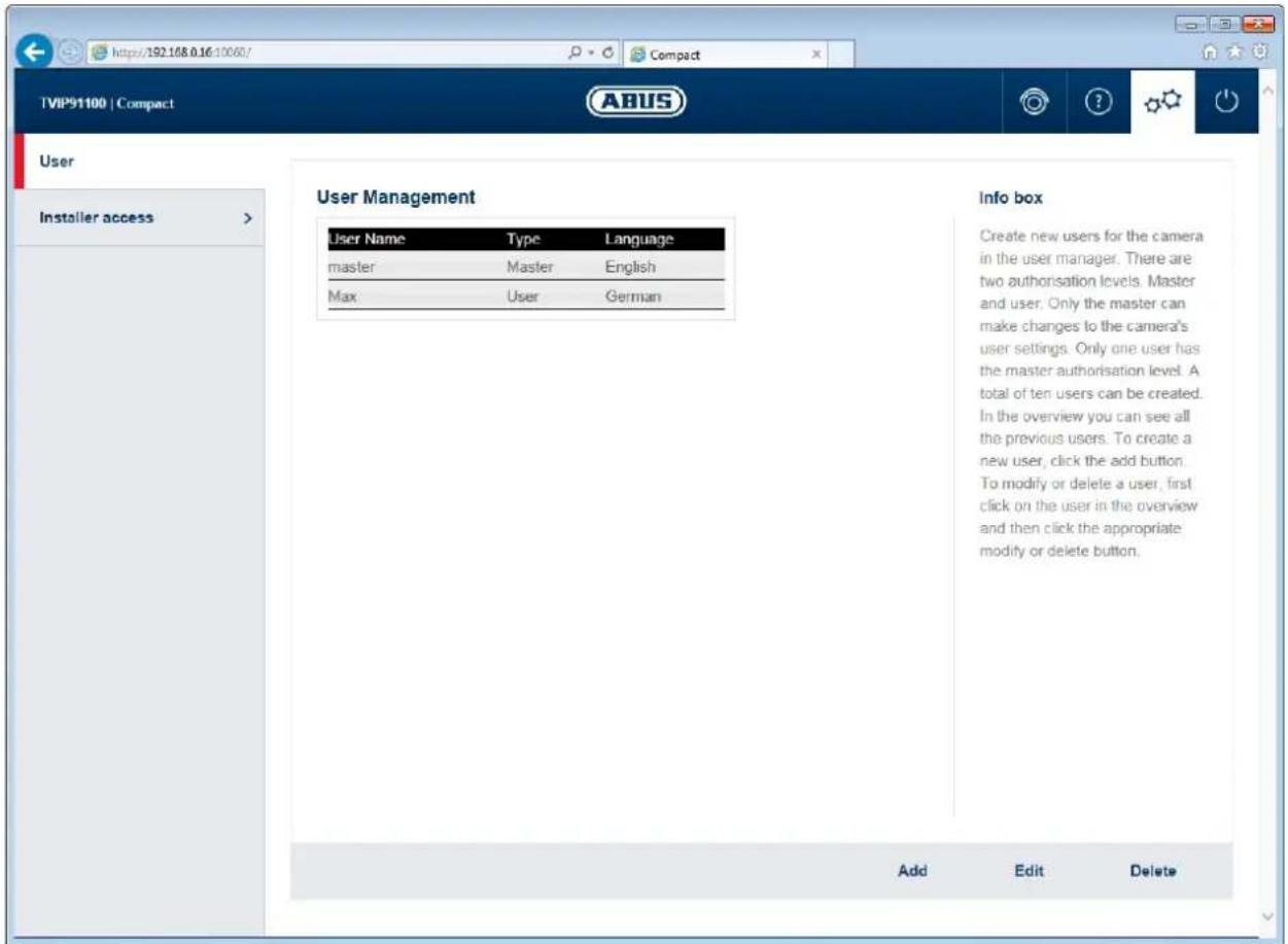
TVP91100 | Compact User Installer access > User Management User Name Type Language master Master English Max User German Info box Create new users for the camera in the user manager. There are two authorisation levels. Master and user. Only the master can make changes to the camera's user settings. Only one user has the master authorisation level. A total of ten users can be created. In the overview you can see all the previous users. To create a new user, click the add button. To modify or delete a user, first click on the user in the overview and then click the appropriate modify or delete button. Add Edit DeleteUser management:
Username: display registered username
Type: the registered user's user account type There may only be one "master" user account type. Up to 10 users can be assigned the "user" account type.
Language: display the language set for the users. Available languages are: English, German, French, Dutch, Danish, Polish, Italian, Spanish, Russian and Swedish
Add: open the menu for registering users of account type "user"
Edit: edit the language or password for "master" or "user"
Delete: delete users of account type "user". Users of account type "master" cannot be deleted.
Password: assign the password for the user.
Permissible characters are: A-Z, a-z, 0-9
Confirm password: confirmation of password for the user.
Change password: ticking the checkbox opens up the menu for changing the password.
Password: enter the new password.
Permissible characters are: A-Z, a-z, 0-9
Confirm password: confirm the password
9.2 Video stream settings
9.2 Deactivate/activate installer access
text_image
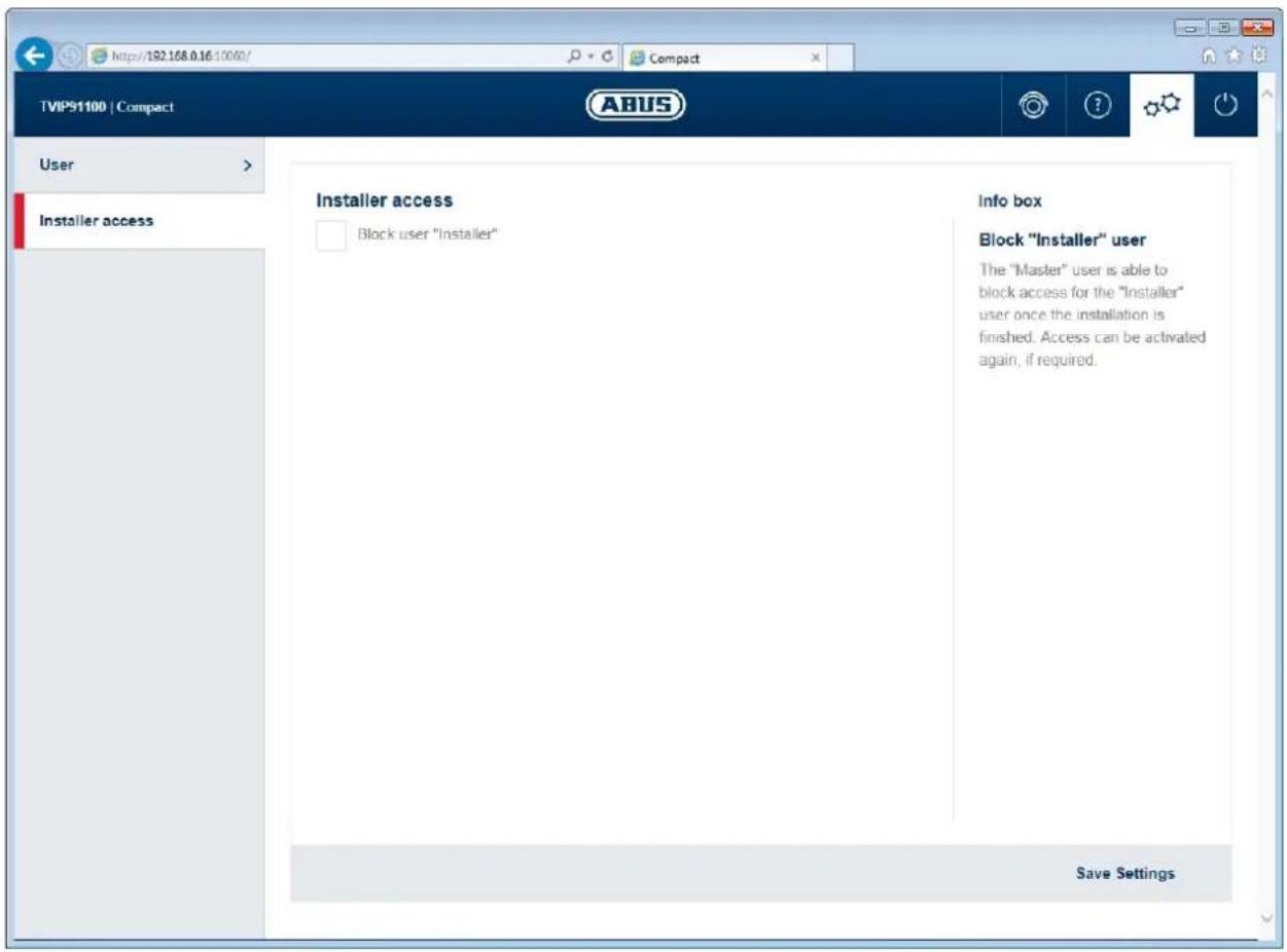
TIP91100 | Compact User Installer access Installer access Block user "Installer" Info box Block "Installer" user The "Master" user is able to block access for the "Installer" user once the installation is finished. Access can be activated again, if required. Save SettingsBlock user "installer": ticking the box will block access for the user "installer". Only the "master" user can unblock access again.

If the "master" user has forgotten their login information, it is possible to perform a factory reset for the "master" user's login information using the "PW reset" button.

If the "installer" user has forgotten their login information, you must load the factory settings for the camera via the "RESET" button. This will restore all usernames and passwords to factory settings.
9.3 Displaying/downloading video from the internal memory
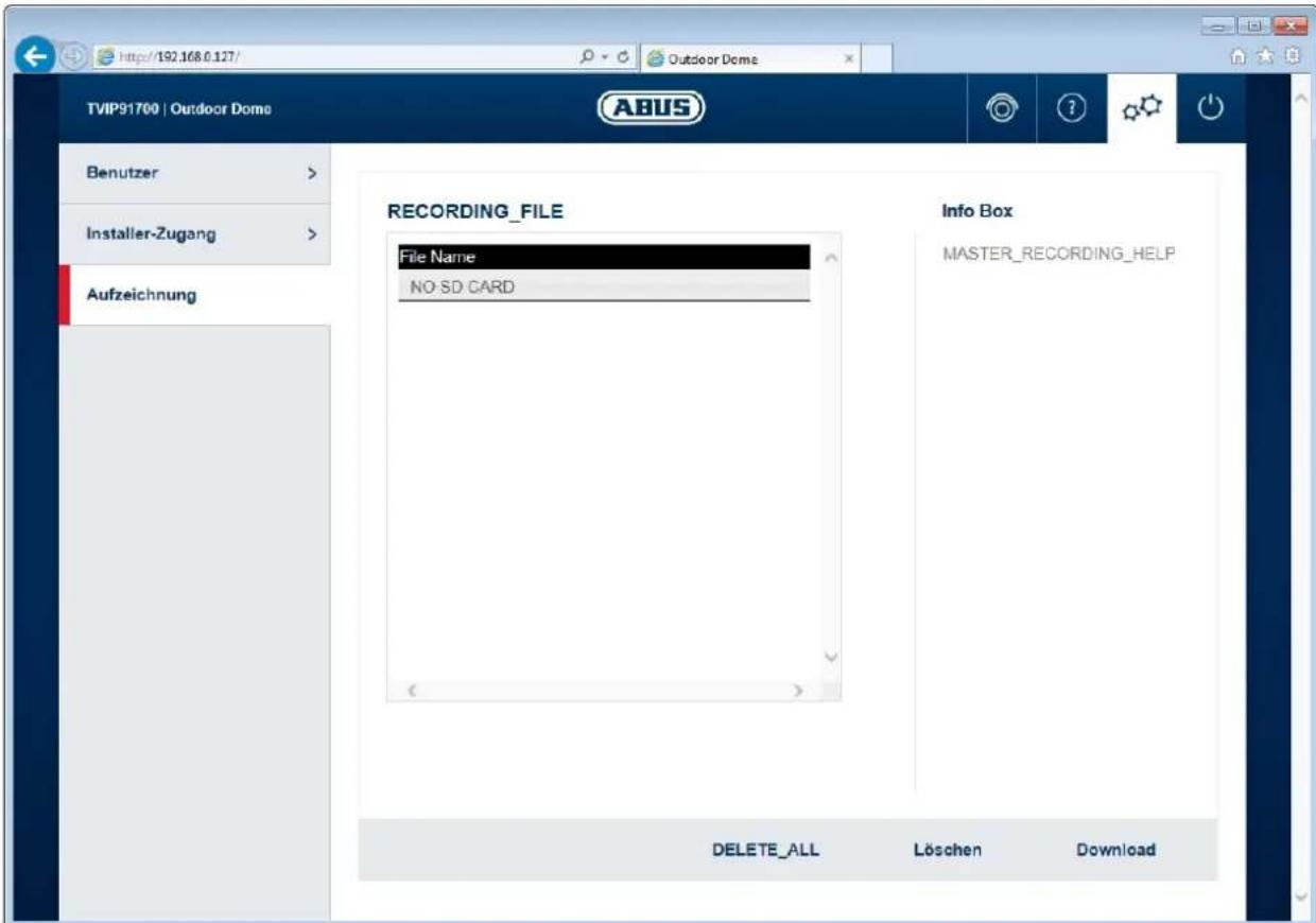
File list: all the video data recorded by the camera during a network failure is displayed here. The maximum file size is 150 MB. If the file size is exceeded due to the length of recording, a new file is opened.
The file name represents the recording's starting time. File format: YYYYMMTThhmmss.avi
Make sure that the camera's time setting is entered correctly before activating the network loss recording function.
Delete all: delete all recorded data from the camera's internal memory. Important: all files are permanently lost after performing this function.
Delete: delete one or more files by marking them in the file list.
Download: download files by marking them in the file list (they will be downloaded one after another).
10. View and configuration menus user "installer"
10.1 Live view
The live view display for the installer user is similar to that of the master user. However, the installer user has extended options for settings such as the set up wizard or extended configuration.
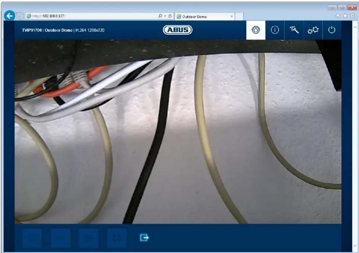
text_image
http://192.168.0.127/ Outdoor Dome TVIP91700 | Outdoor Dome | H.264 1280x720 ABUS(example image of TVIP91700)
| Button/display on screen | Function |
 | Instant image functionThis function saves an instant image from the current video stream in JPEG format. The picture is stored in the following folder:C:/Benutzer/ |
 | Video functionThis function saves a video from the current video stream in AVI format.The video is stored in the following folder:C:/Benutzer/ |
| Activate switching outputThis button can be used to manually activate or deactivate the switching output (e.g. door opener function). | ||
 | Muting the microphone (if available)This button can be used to deactivate the microphone in the camera (TVIP91100) or the microphone in the optional audio input (TVIP92xxx). | |
| Muting the speaker (if available)This button can be used to deactivate the speaker in the optional audio output (TVIP92xxx). | ||
 | Full screen modeSwitching the video picture on the monitor to full screen mode (you can also do this by double clicking within the video frame). You can exit full screen mode by double clicking within the video frame again or pressing the ESC button. | |
 | Zoom/focus setting (only available with TVIP92100, TVIP92300, TVIP926X0 and TVIP92700) | |
 | Status display switching inputThis symbol displays the activation status of the switching input. | |
 | Setting the basic position of the lens (zoom factor 1x, wide angle) | |
 | Save the currently configured zoom and focus position. After restarting the camera, this position is set again. | |
 | Live view page for "master" user | |
 | Information page with explanations of what the buttons do. | |
 | Settings page for "master" user. | |
 | Log out as user. Afterwards the login page is displayed again. | |
10.2 Info page
The info page displays general information about the camera, e.g. installed firmware version or MAC address of the camera.
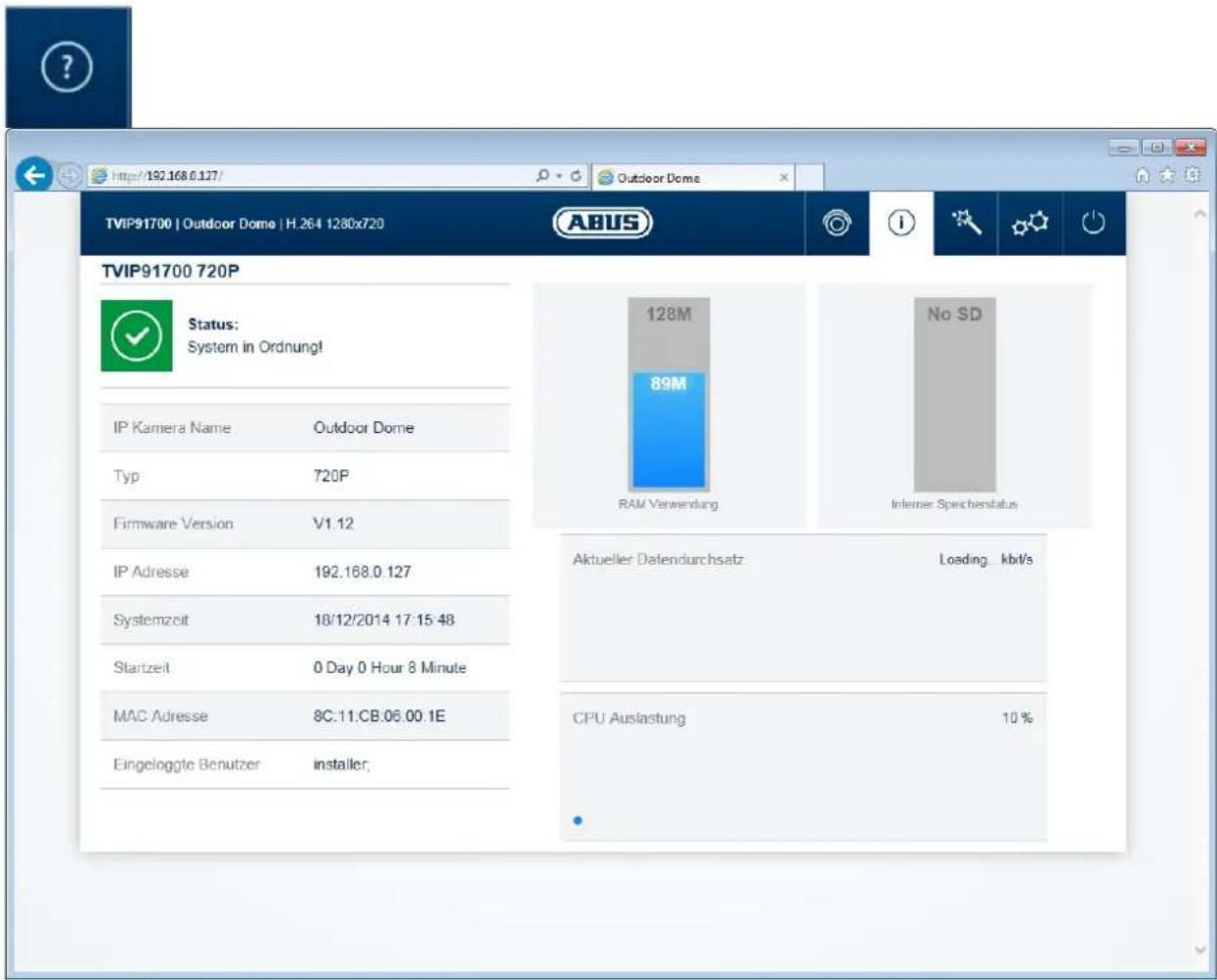
In the area to the upper left, the general status of the system is represented by a symbol.
 | System is running correctlyAll parameters such as system temperature and processor usage are fine. All functions in use are working correctly. |
 | System is faultyErrors have occurred in the system. But these are not critical to the basic functionality of the camera. However, they could cause limitations or malfunctions within certain functions. The system may need to be tested by the installer. |
 | System condition is criticalCertain parameters such as system temperature or processor usage are critical for the system. The system must be tested by the installer immediately. |
IP camera name: display of the camera name. Can be modified using Configuration/System
Type: display of the max. resolution of the camera platform. Firmware version: display of the firmware version currently installed
IP address: display of the IP address currently set
System time: current date/time set:
MAC address: MAC address of the camera (hardware address of the network interface)
Logged on user: user currently logged on
Memory usage: internal memory status
Data throughput: total video and audio bit rate over the network interface (outgoing)
CPU usage: display of the processor usage of the camera.
10.3 Setup wizard
The setup wizard navigates you through the most important menu options the camera has. The setup wizard deals with the following menu options:
Network ▶ DDNS ▶ Text ▶ Date/time ▶ Installer ▶ Service ▶ Storage/Restart

For more information on each settings option see the section "Advanced camera settings".
10.4 Advanced camera settings
10.4.1 Video
10.4.1.1 General
Mirroring: The following image mirroring options are available:
horizontal, vertical, horizontal and vertical
Network frequency: setting for 50 Hz or 60 Hz network frequency.
Shutter preset: this function adjusts certain exposure-related camera settings
by default for scenes inside or outside. Select the appropriate setting for the scene.
10.4.1.2 Day profile
For the day mode settings can be made for the following parameters. The night profile settings in the following point are unaffected by these.
Brightness: image brightness settings
Contrast: image contrast settings
Sharpness: image sharpness settings. A high sharpness value can increase image noise.
Hue: image hue settings
Saturation: image saturation settings
WDR: ticking the checkbox activates the camera's wide dynamic range
(WDR) function.
WDR level: the WDR function intensity can be set here.
Noise reduction: ticking the checkbox activates the DNR function.
Colour image: if this function is activated, a colour image is displayed in day mode.
When it's deactivated, a black and white image is displayed. This function is active by default.
10.4.1.3 Night profile
The settings options for night mode are almost identical to the day profile. The day and night profile settings are independent of one another.
Brightness: see option "Day profile"
Contrast: see option "Day profile"
Sharpness: see option "Day profile"
Hue: see option "Day profile"
Noise reduction: ticking the checkbox activates the corresponding noise reduction function.
2D-DNR level: noise reduction for static images
3D-DNR level: noise reduction for dynamic images
Colour image: see option "Day profile"
IR LEDs off: this function is only available for models TVIP92100 and TVIP92600.
This function helps if the built-in IR LEDs are causing undesired reflections in the video picture (e.g. camera installation behind window panes or too close to objects) Checkbox ticked: IR LEDs are deactivated in night mode Checkbox not ticked: IR LEDs are activated in night mode.
10.4.1.4 Day/night switching
Lighting level: the current lighting level is measured using a light sensor on the camera. Day/night switching is controlled according to the lighting level. The minimum gap required to avoid constant switching between the two is set automatically.
Day > Night: the lighting threshold for switching from day mode to night mode.
Night > Day: the lighting threshold for switching from night mode to day mode.
Schedule: switching between day and night mode using a time schedule. The camera can be set to switch at intervals of 30 minutes.

The time range set represents the day time range. Outside of these times, night mode is used.
Day: the camera stays in day mode permanently. In day mode the infrared cut filter (ICR) is constantly in front of the lens. This means that the image sensor can't pick up any infrared light.
Night: the camera stays in night mode permanently. The infrared cut filter is constantly separated from the lens.
10.4.1.5 Privacy masking
Up to three ranges can be selected in the video. The ranges are automatically named P1, P2 and P3. These ranges are marked as black in the actual video image.
List of ranges: list of all the ranges established
Add: if you press this button, a new entry is created in the list. Then click on the list entry to select a mask further on in the preview. Selecting a second one will remove the previously selected mask. The masks are applied by saving them to the settings.
Delete: deleting a range previously selected in the list of ranges.
10.4.1.6 Video stream settings
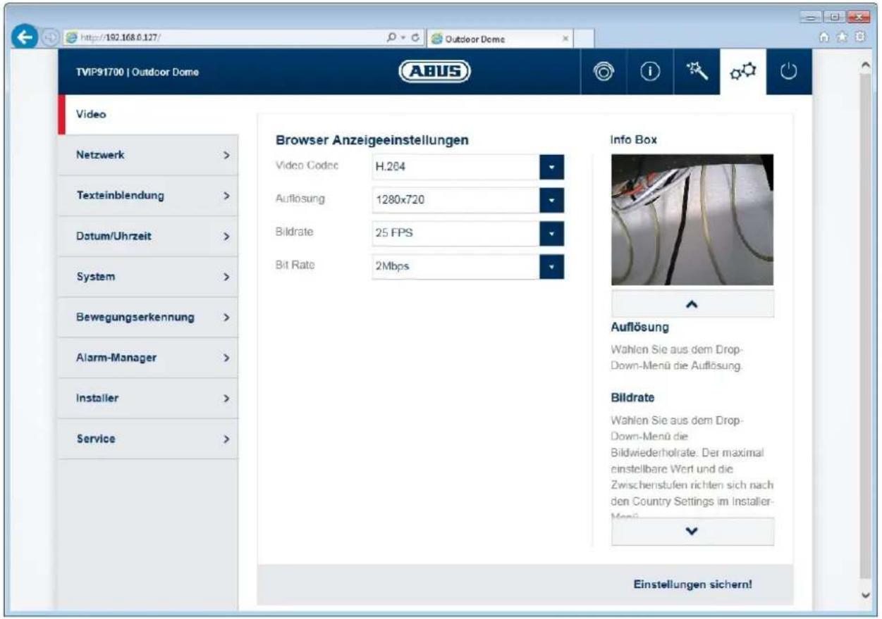
These setting options allow the "installer" user to define the quality settings for displaying in an internet browser and recording using the device (settings Video Stream 1).
TV output: activating or deactivating the analogue video output on the camera (only available for 1080p models)
Video codec: select the video codec. The available codecs are H.264 and MJPEG.
Resolution: the following resolutions are available for the video stream: TVIP91XXX: 1280x720 (default), 800x456, 720x408, 640x360, 320x184 TVIP92XXX: 1920x1080 (default), 1280x720, 800x456, 720x408, 640x360, 320x184
Frame rate: the following frame rates are available for the video stream:
30, 25, 15, 10, 5, 2
Bit rate: the following video bit rates are available for the video stream. A higher video bit rate gives better picture quality as the image is less compressed. TVIP91XXX: 8 Mbit/s up to 32 kBit/s (default is 2 Mbit/s)
TVIP92XXX: 8 Mbit/s up to 64 kBit/s (default is 3 Mbit/s)
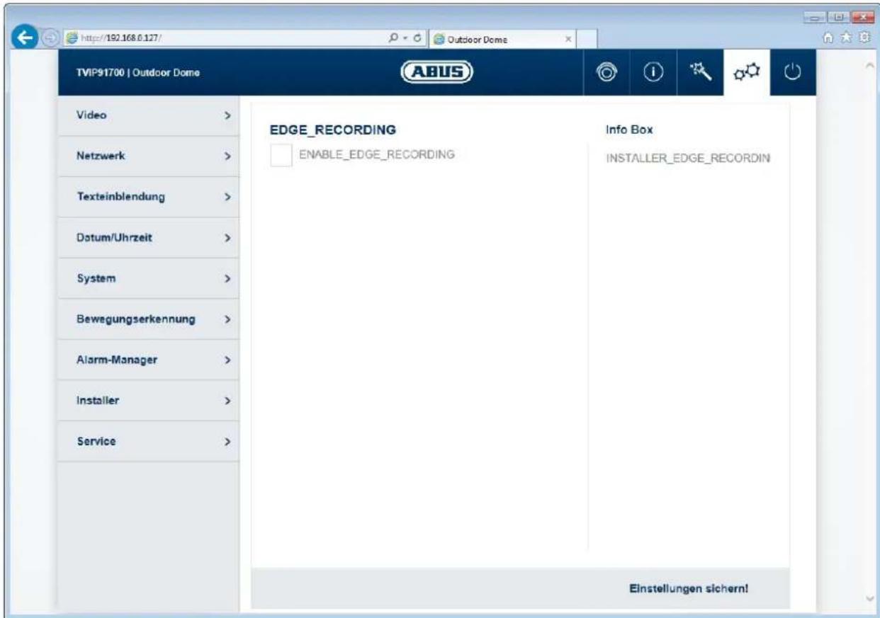
10.4.1.7 Network loss recording
This function allows you to record video data to your internal camera memory in case of IP network failure. Despite the recording device losing its connection to the network, the video data remains available in the camera for this period.
As the function tests the existence of a certain IP address or domain address in the network, it can also be considered "recording when the network device fails". That means that the camera can record internally if another camera fails. This function is useful where both cameras have the same or a similar field of view.
text_image
http://192.168.0.127/ Outdoor Dome TVIP91700 | Outdoor Dome Video > Netzwerk > Texteinblendung > Datum/Uhrzeit > System > Bewegungserkennung > Alarm-Manager > Installer > Service > EDGE_RECORDING ENABLE_EDGE_RECORDING Info Box INSTALLER_EDGE_RECORDIN Einstellungen sichern!Enable network loss recording: activates the function
Cycle recording: if activated, old data is deleted when the internal memory
reaches its maximum capacity so that new data can be stored.
Ping IP address: IP address or domain address that is tested for existence in
the network (this could be the NVR, for example)
Interval: interval for the test. The ping interval determines when
recording starts after the unsuccessful ping. The smaller the interval, the earlier the recording is able to begin (but this does require a good network infrastructure).

If the camera has the function "Record during network failure" and this function is to be used, it's necessary to supply the camera via the 12 V DC terminal (do not use PoE).
10.4.2 Network
10.4.2.1 IPv4 Settings
DHCP: the IP address, subnet mask, gateway (default router) and address for the DNS server are obtained automatically from a DHCP server. An activated DHCP server must be present in the network in this case. The fields on this page are deactivated in this mode and serve as informational fields for the data obtained.
Static IP address: manual setting of the network parameter for IPv4.
IP address: manual setting of the camera's IP address
Subnet mask: manual setting of the camera's subnet mask
Gateway: manual setting of the camera's gateway IP address (also known as default router)
DNS server 1: manual setting of the DNS server's IP address
DNS server 2: alternative IP address of a DNS server
10.4.2.2 Ports
HTTP port: the default port for HTTP transmission is 80. If several IP cameras are located on one subnet, each camera should have its own unique HTTP port.
RTSP port: the default port for RTSP transmission is 554. If several IP cameras are located on one subnet, each camera should have its own unique RTSP port.
RTSP authentication: when authorising an activated RTSP, you must give your username and password for the video to be requested by a client.

If the camera is to be accessed via routers (e.g. from the internet to the local network), port forwarding must be set up for the HTTP and RTSP port in the router. If HTTPS is also being used, port forwarding must be set up for the HTTPS port too.
10.4.2.3 DDNS
Activate DDNS: ticking the checkbox activates the DDNS function.
Select service: select a service provider for the DDNS service.
Username: user account identification with the DDNS service provider
Password: account password with the DDNS service provider
Host name: registered host name with the DDNS service provider

Further information on the "ABUS SERVER" can be found on the help page at the following address:
https://www.abus-server.com/faq.html
10.4.2.4 HTTPS
Activate HTTPS: ticking the checkbox activates the HTTPS function (fixed, self-signed certificate). The HTTP interface is largely active.
HTTPS port: the default port for HTTPS transmission is 443. If several IP cameras are located on one subnet, each camera should have its own unique HTTPS port.

If the camera is to be accessed via routers (e.g. from the internet to the local network), port forwarding must be set up for the HTTP and RTSP port in the router. If HTTPS is also being used, port forwarding must be set up for the HTTPS port too.
10.4.2.5 SMTP/Email
The settings on this page are required to send an email in case of an incident. This action is configured in the "Alarm manager" menu option.
Activate email: ticking the checkbox activates the SMTP/email function.
Sender email address: email address of sender
Sender name: name of sender
SMTP server: SMTP server address of email provider
SMTP server port: SMTP server port
Activate SSL: ticking the checkbox activates the SSL function if the SMTP server supports or requires this.
Activate TLS: ticking the checkbox activates the TLS function if the SMTP server supports or requires this.
Activate authentication: ticking the checkbox activates authentication if the SMTP server supports or requires this.
Username: username for the SMTP server account
Password: password for the SMTP server account
Test email address: assign an optional email address for sending a test email. To send the test email, press the button "Test email".
10.4.3 Overlay text
This function allows certain text, the date and time to be superimposed on to the video.
Activate overlay text: ticking the checkbox activates the function.
Date: superimposes the date
Time: superimposes the time
Text activated: activation of text
Text: assignment of text. Up to a maximum of 16 characters can be assigned. Permissible characters are: A-Z, a-z, 0-9
10.4.4 Date/time
Current date and time: the current date and time settings are displayed here.
Time zone: select the time zone in which the camera is located.
Enable daylight savings time: by ticking the checkbox, you are confirming that the location in which the camera is installed takes part in daylight savings time. Auto: the camera automatically uses the switch-over times every year. Manual: manual switch-over time settings.
NTP server synchronisation: tick the box for the camera to automatically obtain the date and time from a server (please note: the NTP server does not hold any information on the summer/winter time changeover).
NTP server: enter the domain name or the IP address of the time server here.
NTP update interval: update interval for the date and time with the server. An update also takes place when the camera is restarted.
PC time synchronisation: when you save, the date and time from the connected client PC are adopted.
Manual: manual assignment of date and time
10.4.5 System
10.4.5.1 General
Camera name: you can change the default camera name here. Up to a maximum of 16 characters are permitted. Permissible characters are: A-Z, a-z, 0-9
Export configuration: export the camera's configuration data into a file Import configuration: import the camera's configuration data from a file Reset settings: restore all settings to factory settings, except network settings
Include network: after ticking the checkbox and performing the function for resetting settings, all settings including the network parameter are reset.
Status LED: when the checkbox is ticked, the status LED on the camera is active (except TVIP91100).
10.4.5.2 Firmware/Reset
Current firmware: displays the firmware version currently installed Firmware online check: this function checks whether a new firmware version is available on the ABUS website. If there is, the camera offers to download the firmware on to the PC (download link). Then the firmware must be manually installed using the firmware update function.
Firmware update: a more recent version of the camera firmware can be installed here. More information on firmware is available on the ABUS website (www.abus.com).
Restart: manual camera restart
Schedule restart: the camera can be restarted here at a specific frequency.
10.4.5.3 Log file
Log file: data relevant to the system is recorded in the log file. This can help with troubleshooting, for example.
Export: exporting the log file into another file
10.4.6 Motion detection
List of ranges: displays all the ranges of movement set
Display all: tick the checkbox to display a preview of all ranges at the same time.
Range name: name of range
Add: after assigning the range a name and pressing this button, a new
entry is created in the list. Then click on the list entry to select a mask further on in the preview. Selecting a second one will remove the previously selected mask. The masks are applied by saving them to the settings.
Delete: selecting a range in the list and pressing this button deletes the range.
Threshold value: represents the area that has to be changed in the video frame
Day sensitivity: represents the rate of change (day mode)
Night sensitivity: represents the rate of change (night mode)
10.4.7 Alarm manager
Alarm manager: in alarm manager you can create rules for handling events, e.g.
switching a camera switching output during motion detection.
A maximum of one trigger can be used for each rule.
A maximum of one action can be set for each rule.
A maximum of five rules can be created for handling one event.
Trigger: select the event trigger
Schedule: defines when the rule should be active (in half hour increments). If an area is marked as red, it's marked as active.
Action: you can choose between two events:
1) Switching output:
the switching output can either function as a normally closed or normally open contact whereby the active periods can be defined.
There are certain time periods and continuous activities available as an active period.
2) Email
An email can be sent to a specific recipient. The content and subject line can be assigned. It is also possible to select a certain number of pre- and post-alarm images.
Add: adds a new event rule
Edit: edits an event rule
Delete: deletes an event rule
The following triggers for events are available:
Switching input: all cameras in the TVIP9XXXX series have a switching input (an optional cable in dome cameras). On standby, you can select N.O. (normally open) or N.C. (normally closed).
Motion detection: select the camera's internal motion detection. This will analyse all configured masks. It is not possible to detect which mask has made the trigger.
Restart: triggering when the camera restarts
Watchdog error: the system can restart automatically after a serious malfunction (this is known as 'watchdog'). This can be used as a trigger.
Day/night switching: choose between switching to day or night mode as an event trigger.
Authentication error: entering an incorrect password twice can be used as a trigger.
Back up settings: the last page of event configuration displays an overview of all rule parameters that have been set. You must then press the "Save" button.
10.4.8 Audio
This option only appears if the camera has audio functionality. There is one model with a built-in microphone (TVIP91100) in addition to five models with connectible audio input and output devices (TVIP92100, TVIP92300, TVIP92500, TVIP926X0 and TVIP92700).
Audio input: settings for input volume
Audio output: settings for output volume
10.4.9 Installer
Language: select language for the "installer" user. The settings pages available are displayed in this language. The language settings for the "master" and "user" users are unaffected by this.

The home page and login window are displayed in the language of the PC as long as this language is available in the camera. If the language is not available, it will be displayed in English.
In the next few steps, the passwords for the "installer" user, recording client (e.g. NVR) and mobile client (e.g. APP) can be set.
Change password: tick the checkbox to show the field for entering your password and confirming this password.
Password: enter the new password.
Confirm password: confirm the new password.
10.4.10 Service
Country of service: select the country responsible for providing support for the camera in use.
Network frequency: set the network frequency (only 720p camera types). In Germany the standard network frequency is 50 Hz.
Send data: with approval from the "installer" user, the camera settings data and log file can be sent to ABUS Support. This is dependent on the previous setting in your country of service.
Service user: if service is required, this function can create a username and password.
Username: service
Password: the password must be entered. Max. 16 characters. Permissible characters are:
11. Maintenance and cleaning
11.1 Function test
Regularly check the technical safety of the product, e.g. check the housing for damage.
If it seems that it may no longer be possible to operate the device safely, stop using the product and secure it to prevent unintentional use.
It is likely that safe operation is no longer possible in the event that:
- the device shows signs of visible damage
- the device no longer works correctly
- the device has been stored in adverse conditions for a long period of time
- the device has been exposed to stresses during transportation.

Please note:
You do not need to perform any maintenance on the product. There are no components requiring servicing or checking inside the product. Never open it.
11.2 Cleaning
Clean the product with a clean, dry cloth. The cloth can be dampened with lukewarm water if there is dirt that is hard to remove.

Make sure that no liquids enter the inside of the device, as this will destroy it. Do not use any chemical cleaning agents, as these could damage the surface of the housing.
12. Disposal
Devices displaying this symbol may not be disposed of with domestic waste. At the end of its service life, dispose of the product according to the applicable legal requirements.
Please contact your dealer or dispose of the products at the local collection point for electronic waste.
- Technical data
| TVIP91100 | TVIP91300 | TVIP91600 | TVIP91700 | |
| Image sensor | 1/3 inch progressive scan CMOS | |||
| Camera type | Compact Indfor dome Outdoor tube Outdoor dome | |||
| Resolution | 720p | |||
| Pixels (total) | 1280 x 800 | |||
| Pixels (effective) | 1280 x 720 | |||
| Lens | Fixed lens | |||
| Focal length | 3.6 mm | |||
| Horizontal angle of view | 78° | |||
| Lens control | AES | |||
| Day/night switching | IR cut filter (ICR), colour/B/W | |||
| IR LEDs | 3 high performance LEDs | - | 4 performance LEDs | high - |
| IR range | 10 m - 15 m - | |||
| Minimum illumination (colour) | 0,5 Lux 0,5 Lux | Lux 0,5 Lux 0,5 Lux | ||
| Minimum illumination (IR) | 0 Lux | 0 Lux (external IR) | 0 | 0 Lux (external Lux IR) |
| Noise reduction | 2D DNR, 3D DNR | |||
| Electronic shutter | Auto | |||
| White balance | AWB | |||
| Amplifier control | Auto | |||
| Backlight compensation | WDR | |||
| Dynamic range (WDR) | Max. 46 dB | |||
| Video system | IP | |||
| Privacy masking | 3 freely configurable masks | |||
| ONVIF | ONVIF profile S | |||
| Connections | 1 x RJ45, 1 x DC, 1 x alarm input, 1 x alarm output, 1 x audio input, 1 x audio output, 1 x FBAS | 1 x RJ45, 1 x DC, 1 x FBAS optional: 1 x alarm input, 1 x alarm output, 1 x audio input, 1 x audio output | 1 x RJ45, 1 x DC, 1 x FBAS, 1 x alarm input, 1 x alarm output, 1 x USB | 1 x RJ45, 1 x DC, 1 x alarm input, 1 x alarm output, 1 x audio input, 1 x audio output, 1 x FBAS |
| Power supply | 12 V DC | |||
| PoE | 802.3af | |||
| Power consumption | 270 mA (max.) | 140 mA (max.) 270 | mA (max.) 140 mA | (max.) |
| Operating temperature | 0°C–+50°C | 0°C–+50°C | -10°C–+50°C | -10°C–+50°C |
| Humidity | 0–75% non-condensing 0–85% non-condensing | |||
| Protection class | IP24 | IP24 | IP66 | IP66 |
| Dimensions (WxHxD) | 82 x 82 x 145 mm | 141 x 141 x 98 mm | 82 x 82 x 238 mm | 141 x 141 x 102 mm |
| Weight | 560 g 690 g | 1090 g 1020 g | ||
| Certifications | CE, RoHS, REACH | |||
| TVIP92100 | TVIP92300 | TVIP92500 | TVIP92600 | TVIP92700 | |
| Image sensor | 1/2.8 inch Progressive Scan Sony Exmore CMOS | ||||
| DSP | Sony XARINA | ||||
| Camera type | Compact Indoor dome Box | Outdoor tube | Outdoor | dome | |
| Resolution | 1080p | ||||
| Pixels (total) | 1952 x 1116 | ||||
| Pixels (effective) | 1920 x 1080 | ||||
| Lens | Motor zoom Motor zoom | ||||
| Focal length | 3-9 mm 3-9 mm - 9-22 mm 3-9 mm | ||||
| Horizontal angle of view | 35°-90° | 32°-90° | - | 13°-30° | 32°- |
| Lens control | Auto iris | ||||
| Day/night switching | IR cut filter (ICR), colour/B/W | ||||
| IR LEDs | 3 high performance LEDs | - | - | 4 performance LEDs | -high |
| IR range | 10 m - - | 20 m - | |||
| Minimum illumination (colour) | 0,2 Lux 0,2 Lux 0,2 Lux | 0,35 | Lux 0,2 Lux | ||
| Minimum illumination (IR) | 0 Lux | 0 Lux (external IR) | 0 Lux (IR extern) | 0 Lux | 0 Lux (external IR) |
| Noise reduction | 2D DNR, 3D DNR | ||||
| Electronic shutter | Auto | ||||
| White balance | ATW | ||||
| Amplifier control | Auto | ||||
| Backlight compensation | WDR | ||||
| Dynamic range (WDR) | >100 dB | ||||
| Video system | IP | ||||
| Privacy masking | 3 freely configurable masks | ||||
| ONVIF | ONVIF profile S | ||||
| Connections | 1 x RJ45, 1 x DC, 1 x alarm input, 1 x alarm output, 1 x audio input, 1 x audio output, 1 x FBAS | 1 x RJ45, 1 x DC, 1 x FBAS optional: 1 x alarm input, 1 x alarm output, 1 x audio input, 1 x audio output, 1 x FBAS | 1 x RJ45, 1 x DC, 1 x FBAS, 1 x alarm input, 1 x alarm output, 1 x USB | 1 x RJ45, 1 x DC, 1 x alarm input, 1 x alarm output, 1 x audio input, 1 x audio output, 1 x FBAS | 1 x RJ45, 1 x DC, 1 x FBAS optional: 1 x alarm input, 1 x alarm output, 1 x audio input, 1 x audio output, 1 x audio output |
| Power supply | 12 V DC | ||||
| PoE | 802.3af | ||||
| Power consumption | 480 mA (max.) | 300 mA (max.) | 250 mA (max.) | 500 mA (max.) | 300 mA (max.) |
| Operating temperature | 0°C-+50°C | 0°C-+50°C | 0°C-+50°C | -25°C-+50°C | -25°C-+50°C |
| Humidity | 0-75% non-condensing | 0-85% non-condensing | |||
| Protection class | IP24 | IP24 | IP24 | IP66 | IP66 |
| Dimensions (WxHxD) | 82 x 82 x 145 mm | 141 x 141 x 98 mm | 63 x 63 x 129 mm | 82 x 82 x 238 mm | 141 x 141 x 102 mm |
| Weight | 670 g | 680 g | 355 g | 1090 g | 1010 g |
| Certifications | CE, RoHS, REACH | ||||
| TVIP92610 | |||||
| Image sensor | 1/2,8" Progressive Scan Sony Exmore CMOS | ||||
| DSP | Sony XARINA | ||||
| Camera type | Outdoor Tube | ||||
| Resolution | 1080p | ||||
| Pixels (total) | 1952 x 1116 | ||||
| Pixels (effective) | 1920 x 1080 | ||||
| Lens | Motor-Zoom | ||||
| Focal length | 3,0 – 9,0 mm | ||||
| Horizontal angle of view | 35° – 90° | ||||
| Lens control | Auto Iris | ||||
| Day/night switching | IR cut filter (ICR), Color / B/W | ||||
| IR LEDs | High performance LEDs | ||||
| IR range | 20 m | ||||
| Minimum illumination (colour) | 0,2 Lux | ||||
| Minimum illumination (IR) | 0 Lux | ||||
| Noise reduction | 2D DNR, 3D DNR | ||||
| Electronic shutter | Auto | ||||
| White balance | ATW | ||||
| Amplifier control | Auto | ||||
| Backlight compensation | WDR | ||||
| Dynamic range (WDR) | >100 dB | ||||
| Video system | IP | ||||
| Privacy masking | 3 freely configurable masks | ||||
| ONVIF | ONVIF Profile S | ||||
| Connections | 1 x RJ45, 1 x DC, 1 x alarm input, 1 x alarm output, 1 x audio input, 1 x audio output, 1 x FBAS | ||||
| Power supply | 12 V DC | ||||
| PoE | 802.3af | ||||
| Power consumption | 500 mA (max.) | ||||
| Operating temperature | -25°C - +50°C | ||||
| Humidity | 0 - 85%, non-condensing | ||||
| Protection class | IP66 | ||||
| Dimensions (WxHxD) | 82 x 82 x 238 mm | ||||
| Weight | 1090 g | ||||
| Certifications | CE, RoHS, Reach | ||||
TVIP91XXX / TVIP92XXX
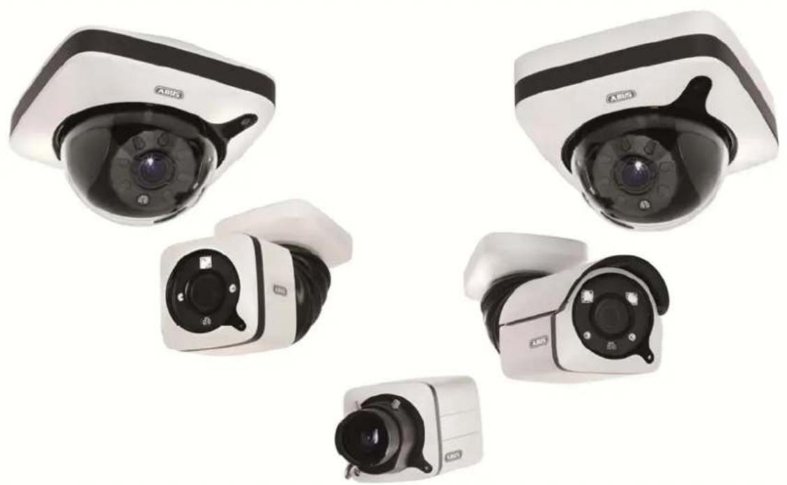
natural_image
Five different ASIS security cameras shown from different angles (no visible text or labels)Version 09/2016
TVIP91XXX
TVIP92XXX
CE
text_image
Technical diagram of a Mitsubishi industrial sensor with numbered components and labeled parts
text_image
Technical diagram of a mechanical device with numbered components and exploded view indicatorsDE
- lens
- Photo sensor
- Microphone
- IR LEDs
- Base plate
- Safety screws
①
- Alarm input and output
- Power supply 12V
- RJ45 connection, PoE capable
- Password reset
- Reset button
- Power LED
- Safety screws
- Breakout point, if lateral cable
routing is desired - 3-axle mount
FR
text_image
Technical diagram of a device with numbered components and labeled parts in Chinese
text_image
Technical diagram of a dome-shaped device with numbered labels pointing to its components.
B
-
Reset button
-
Password reset
-
Status LED for 12 V power supply
-
Lens
-
Photo sensor
-
Fixing screws for camera module
FR
-
Recess for removing the cover
-
Recess for concealed cable routing
-
Breakout point, if lateral cable
routing is desired
-
12 V power supply
-
RI45 connection, PoE capable
FR
text_image
Technical diagram of an Airbus AG motor with numbered components and labeled parts
text_image
Technical diagram of a mechanical device with numbered components and exploded view labelsDH
- lens
- Photo sensor
- Status LED
- IR LEDs
- Base plate
- Safety screws
- Sun shield
FR
- Breakout point, if lateral cable routing is desired
- 3-axle mount
- Password reset
- Reset button
- Alarm input and output
- Power supply 12 VDC
- RI45 connection, PoE capable
PR
①
text_image
Technical diagram of a mechanical device with numbered components and labeled parts in Chinese
text_image
Technical diagram of a mechanical component with numbered parts labeled 9, 10, and 11

DE
- Reset button
- Password reset
- Status LED for 12 V power supply
- Lens
- Photo sensor
- Fixing screws for camera module
FR
- 12 V power supply
- RJ45 connection, PoE capable
- Recess for removing the cover
- Recess for concealed cable routing
- PG screw connection M25 for lateral cable routing
FR
text_image
Technical diagram of a mechanical component with numbered parts labeled ① to ⑥
text_image
Technical diagram of a mechanical device with numbered components and exploded view labelsUR
- Lens
- Photo sensor
- Microphone
- IR LEDs
- Base plate
- Safety screws
- Alarm input and output
- Power supply 12V
- RJ45 connection, PoE capable
FR
[Non-Text]
[Non-Text]
[Non-Text]
[Non-Text]
[Non-Text]
[Non-Text]
[Non-Text]
[Non-Text]
[Non-Text]
FR
- (1)
- [Non-Text]
18.
PL
- (二)
B. - 6.7
- 12
- 四、15
- 18
- 10.
- [Non-Text]
[Non-Text]
[Non-Text]
[Non-Text]
[Non-Text]
10. 11. - 10. 11.
- 10. 11.
- 10. 11.
- 10.
- 10.
- 10.
- [Non-Text]
[Non-Text]
[Non-Text]
[Non-Text]
[Non-Text]
[Non-Text]
[Non-Text]
[Non-Text]
[Non-Text]
[Non-Text]
[Non-Text]
[Non-Text]
广力云
。
[Non-Text]
[Non-Text]
[Non-Text]
[Non-Text]
[Non-Text]
[Non-Text]
[Non-Text]
[Non-Text]
[Non-Text]
[Non-Text]
广力云
。
[Non-Text]
[Non-Text]
[Non-Text]
[Non-Text]
[Non-Text]
[Non-Text]
[Non-Text]
[Non-Text]
[Non-Text]
[Non-Text]
[Non-Text]
[Non-Text]
[Non-Text]
[Non-Text]
[Non-Text]
[Non-Text]
[Non-Text]
[Non-Text]
[Non-Text]
1
1
1
1
1
[Non-Text]
[Non-Text]
[Non-Text]
[Non-Text]
[Non-Text]
[Non-Text]
[Non-Text]
[Non-Text]
[Non-Text]
[Non-Text]
[Non-Text]
[Non-Text]
[Non-Text]
。
[Non-Text]
[Non-Text]
[Non-Text]
[Non-Text]
[Non-Text]
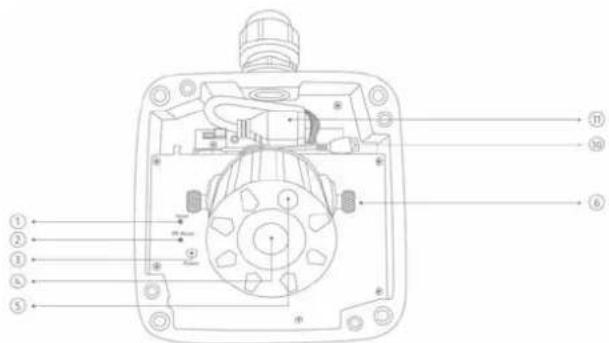
text_image
Technical diagram of a mechanical device with numbered components for identification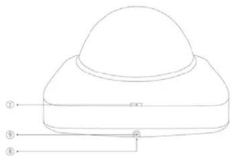
text_image
Technical diagram of a device with numbered labels pointing to its components.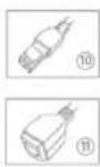
DE
- Reset button / Zoom In
- Password reset / Zoom Out
- Status LED for 12 V power supply
- Lens
- Photo sensor
- Fixing screws for camera module
FIR
- Recess for removing the cover
- Recess for concealed cable routing
- Breakout point, if lateral cable routing is desired
- 12 V power supply
- RJ45 connection, PoE capable
FR
- Lens connection
- ¼ inch thread on top
and bottom sides - Status LED
- Lens base (CS mount)
- Photo sensor
FR
The Ground Truth image displays a single, solid horizontal line. According to Rule 2 (UNDERSCORE & LINE RULES), this is a stylistic or background line, not a placeholder underscore. Therefore, the OCR result must ignore it and output nothing or only meaningful text. The provided OCR content is "____", which consists of four underscores. This is an incorrect interpretation of the line as a placeholder, violating the rule that stylistic lines must be ignored. The OCR has hallucinated placeholder underscores where none exist in the GT. Hence, the OCR result is inconsistent with the Ground Truth.
[Non-Text]
[Non-Text]
[Non-Text]
FR
- Analogue video output for service
- Status LED for 12 V power supply
- Audio input
- Audio output
- Reset button
- Reset button
- Password reset
- Micro SD card slot
- 12 V power supply
- Alarm input and output
- RI45 connection, PoE capable
- Earth connection
FR
(1) 本说明仅供参考。
IT
text_image
Technical diagram of an ABUS industrial sensor with numbered components and labeled parts
text_image
Technical diagram of a mechanical device with numbered parts and corresponding component labels in Chinese.DE
- Lens
- Phot
- Status LED
- IR LEDS
- Base plate
- Safety screws
- Sun shield
用
- Breakout point, if lateral cable routing is desired
- 3-axle mount
- Password reset
- Reset button
- Alarm input and output
- Power supply 12 VDC
- RJ45 connection, PoE capable
- Audio Input
- Audio output
- Analogue video output for service
四
⑪
text_image
Technical diagram of a mechanical device with numbered components and directional arrows indicating assembly or flow.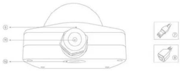
text_image
Technical diagram of a mechanical component with labeled parts and two inset images showing internal components.DE
- Reset button / Zoom In
- Password reset / Zoom Out
- Status LED for 12 V power supply
- Lens
- Photo sensor
- Fixing screws for camera module
图
- 12 V power supply
- R045 connection, PoE capable
- Recess for removing the cover
- Recess for concealed cable routing
- PG screw connection M25 for lateral cable routing
m
natural_image
Two green plastic electrical connectors shown from different angles (no text or symbols visible)text_image
TVIP92700 | Outdoor Dome | H.264 1920X1080 ABUS Install Plugin > There is no Browser plugin installed. You should install the TVIP Plugin to view camera video stream. Continue without Plugin > Image display is slower without plugin.
natural_image
Interior view of a computer lab with electronic equipment and a person using a laptop (no visible text or symbols)text_image
Dateiname 20150401163627_20150401164632_Indoor_Dome_8C11CB060019.avinatural_image
Close-up of a car interior with curved pipes and wiring, no visible text or symbols on the main subject.Image : TVIP91700
natural_image
Five different ARIS security cameras shown from different angles (no text or labels visible)V e r s i e TVIP91XXX TVIP92XXX 9 / 2 0 CE 16
text_image
Technical diagram of a Mitsubishi industrial sensor with numbered components and labeled parts
text_image
Technical diagram of a mechanical device with numbered components and exploded view labelsDE
- lens
- Photo sensor
- Microphone
- IR LEDs
- Base plate
- Safety screws
①
- Alarm input and output
- Power supply 12V
- RJ45 connection, PoE capable
- Password reset
- Reset button
- Power LED
- Safety screws
- Breakout point, if lateral cable
routing is desired - 3-axle mount
FR
text_image
Technical diagram of a device with numbered components and labeled parts in Chinese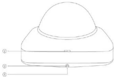
text_image
Technical diagram of a dome-shaped device with numbered labels pointing to its components.
B
-
Reset button
-
Password reset
-
Status LED for 12 V power supply
-
Lens
-
Photo sensor
-
Fixing screws for camera module
FR
-
Recess for removing the cover
-
Recess for concealed cable routing
-
Breakout point, if lateral cable
routing is desired
-
12 V power supply
-
RI45 connection, PoE capable
FR
text_image
Technical diagram of an Airbus AG motor with numbered components and labeled parts
text_image
Technical diagram of a mechanical device with numbered components and exploded view labelsDH
- lens
- Photo sensor
- Status LED
- IR LEDs
- Base plate
- Safety screws
- Sun shield
FR
- Breakout point, if lateral cable routing is desired
- 3-axle mount
- Password reset
- Reset button
- Alarm input and output
- Power supply 12 VDC
- RI45 connection, PoE capable
PR
①
text_image
Technical diagram of a mechanical device with numbered components and labeled parts in Chinese
text_image
Technical diagram of a mechanical component with numbered parts labeled 9, 10, and 11

DE
- Reset button
- Password reset
- Status LED for 12 V power supply
- Lens
- Photo sensor
- Fixing screws for camera module
F8
- 12 V power supply
- RJ45 connection, PoE capable
- Recess for removing the cover
- Recess for concealed cable routing
- PG screw connection M25 for lateral cable routing
FR
text_image
Technical diagram of a mechanical component with numbered parts labeled ① to ⑥
text_image
Technical diagram of a mechanical device with numbered components and exploded view labelsUR
-
Lens
-
Photo sensor
-
Microphone
-
IR LEDs
-
Base plate
-
Safety screws
-
Alarm input and output
-
Power supply 12V
-
R045 connection, PoE capable
FR
-
Audio input
-
Audio output
-
Analogue video output for service
-
Password reset
-
Reset button
-
Power Ltd
-
Safety screws
-
Breakout point, if lateral cable
-
2 cycle mount
-
3-die mount
FR
text_image
Technical diagram of a mechanical device with numbered components for identification
text_image
Technical diagram of a device with numbered components and corresponding close-up images labeled ⑩ and ⑪.DE
- Reset button / Zoom In
- Password reset / Zoom Out
- Status LED for 12 V power supply
- Lens
- Photo sensor
- Fixing screws for camera module
FIR
- Recess for removing the cover
- Recess for concealed cable routing
- Breakout point, if lateral cable routing is desired
- 12 V power supply
- RJ45 connection, PoE capable
FR
- Lens connection
- ¼ inch thread on top
and bottom sides - Status LED
- Lens base (CS mount)
- Photo sensor
FR
- Analogue video output for service
- Status LED for 12 V power supply
- Audio input
- Audio output
- Reset button
- Reset button
- Password reset
- Micro SD card slot
- 12 V power supply
- Alarm input and output
- RI45 connection, PoE capable
FR
©
IT
text_image
Technical diagram of an ABUS industrial sensor with numbered components and labeled parts
text_image
Technical diagram of a mechanical device with numbered parts and corresponding component labels in ChineseDE
- Lens
- Phot
- Status LED
- IR LEDS
- Base plate
- Safety screws
- Sun shield
用
- Breakout point, if lateral cable routing is desired
- 3-axle mount
- Password reset
- Reset button
- Alarm input and output
- Power supply 12 VDC
- RJ45 connection, PoE capable
- Audio Input
- Audio output
- Analogue video output for service
四
DIN
text_image
Technical diagram of a mechanical device with numbered components and directional arrows indicating assembly or flow.
text_image
Technical diagram of a mechanical component with labeled parts and two inset images showing internal components.DE
- Reset button / Zoom In
- Password reset / Zoom Out
- Status LED for 12 V power supply
- Lens
- Photo sensor
- Fixing screws for camera module
图
- 12 V power supply
B. RJ45 connection, PoE capable - Recess for removing the cover
- Recess for concealed cable routing
- PG screw connection M25 for lateral cable routing
m
natural_image
Two green plastic electrical connectors shown from different angles (no text or symbols visible)Voedingsspanning, 12 V DC
TVIP9XXXX
text_image
TVIP92700 | Outdoor Dome | H.264 1920X1080 ABUS Install Plugin > There is no Browser plugin installed. You should install the TVIP Plugin to view camera video stream. Continue without Plugin > Image display is slower without plugin.
7.6 Camera integreren in ABUS VMS / ABUS VMS Express
7.8 Camera integreren in IPCam
natural_image
Interior view of a computer lab with electronic equipment and a person at the desk (no visible text or symbols)text_image
http://192.168.0.127/ Outdoor Dome TVIP91700 | Outdoor Dome | H.264 1280x720 ABUS30, 25, 15, 10, 5, 2
natural_image
Five different ARIS security cameras shown from different angles (no text or labels visible)Version 09/2016
TVIP91XXX
TVIP92XXX
CE
text_image
Technical diagram of a Mitsubishi industrial sensor with numbered components and labeled parts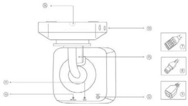
text_image
Technical diagram of a mechanical device with numbered components and exploded view indicatorsDE
- lens
- Photo sensor
- Microphone
- IR LEDs
- Base plate
- Safety screws
①
- Alarm input and output
- Power supply 12V
- RJ45 connection, PoE capable
- Password reset
- Reset button
- Power LED
- Safety screws
- Breakout point, if lateral cable
routing is desired - 3-axle mount
FR
text_image
Technical diagram of a device with numbered components and labeled parts in Chinese
text_image
Technical diagram of a dome-shaped device with numbered labels pointing to its components.
B
-
Reset button
-
Password reset
-
Status LED for 12 V power supply
-
Lens
-
Photo sensor
-
Fixing screws for camera module
EIR
-
Recess for removing the cover
-
Recess for concealed cable routing
-
Breakout point, if lateral cable
routing is desired
-
12 V power supply
-
RI45 connection, PoE capable
FR
text_image
Technical diagram of an ABUS industrial sensor with numbered components and labeled parts
text_image
Technical diagram of a mechanical device with numbered components and exploded view labelsDE
- lens
- Photo sensor
- Status LED
- IR LEDs
- Base plate
- Safety screws
- Sun shield
FR
- Breakout point, if lateral cable routing is desired
- 3-axle mount
- Password reset
- Reset button
- Alarm input and output
- Power supply 12 VDC
- RI45 connection, PoE capable
PR
①
text_image
Technical diagram of a mechanical device with numbered components and labeled parts in Chinese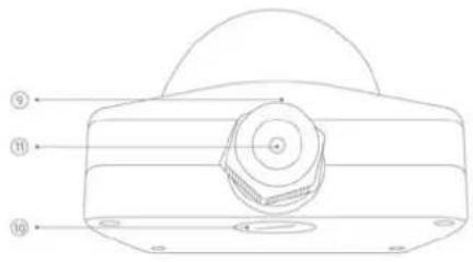
text_image
Technical diagram of a mechanical component with numbered parts labeled ⑨, ⑪, and ⑩.

DE
- Reset button
- Password reset
- Status LED for 12 V power supply
- Lens
- Photo sensor
- Fixing screws for camera module
FR
- 12 V power supply
- RJ45 connection, PoE capable
- Recess for removing the cover
- Recess for concealed cable routing
- PG screw connection M25 for lateral cable routing
FR
text_image
Technical diagram of a mechanical device with numbered components and labeled parts
text_image
Technical diagram of a mechanical device with numbered components and labeled parts in ChineseUR
- Lens
- Photo sensor
- Microphone
- IR LEDs
- Base plate
- Safety screws
- Alarm input and output
- Power supply 12V
- RJ45 connection, PoE capable
FR
[Non-Text]
[Non-Text]
[Non-Text]
[Non-Text]
[Non-Text]
[Non-Text]
[Non-Text]
[Non-Text]
[Non-Text]
FR
- (1)
- [Non-Text]
18.
PL
- (二)
B. - 6.7
- 12
- 四、15
- 10
- [Non-Text]
B. - 6.7
- [Non-Text]
B. - [Non-Text]
- 24
6.7 - 71
[Non-Text]
B. - [Non-Text]
B.
10.
text_image
Technical diagram of a mechanical device with numbered components for identification
text_image
Technical diagram of a device with numbered components and corresponding close-up images labeled ⑩ and ⑪.DE
- Reset button / Zoom In
- Password reset / Zoom Out
- Status LED for 12 V power supply
- Lens
- Photo sensor
- Fixing screws for camera module
广
- Recess for removing the cover
- Recess for concealed cable routing
- Breakout point, if lateral cable routing is desired
- 12 V power supply
- RJ45 connection, PoE capable
FR
- Lens connection
- ¼ inch thread on top
and bottom sides - Status LED
- Lens base (CS mount)
- Photo sensor
FR
- Analogue video output for service
- Status LED for 12 V power supply
- Audio input
- Audio output
- Reset button
- Reset button
- Password reset
- Micro SD card slot
- 12 V power supply
- Alarm input and output
- RI45 connection, PoE capable
- Earth connection
FR
(1) 本次股东大会的召集和召开程序
PL
text_image
Technical diagram of an ABUS industrial sensor with numbered components and labeled parts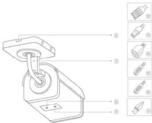
text_image
Technical diagram of a mechanical device with numbered parts and corresponding component labels in ChineseDE
- Lens
- Phot
- Status LED
- IR LEDS
- Base plate
- Safety screws
- Sun shield
用
- Breakout point, if lateral cable routing is desired
- 3-axle mount
- Password reset
- Reset button
- Alarm input and output
- Power supply 12 VDC
- RJ45 connection, PoE capable
- Audio Input
- Audio output
- Analogue video output for service
四
⑪
text_image
Technical diagram of a mechanical device with numbered components and directional arrows indicating assembly or flow.
text_image
Technical diagram of a mechanical component with labeled parts and two inset images showing internal components.DE
- Reset button / Zoom In
- Password reset / Zoom Out
- Status LED for 12 V power supply
- Lens
- Photo sensor
- Fixing screws for camera module
图
- 12 V power supply
- R045 connection, PoE capable
- Recess for removing the cover
- Recess for concealed cable routing
- PG screw connection M25 for lateral cable routing
m
natural_image
Two green electrical connectors shown from different angles (no text or symbols visible)text_image
TVIP92700 | Outdoor Dome | H.264 1920X1080 ABUS Install Plugin > There is no Browser plugin installed. You should install the TVIP Plugin to view camera video stream. Continue without Plugin > Image display is slower without plugin.
7.4 Startside (login-side)
natural_image
Interior view of a computer lab with electronic equipment and a person working at a desk (no visible text or symbols)text_image
Dateiname 20150401163627_20150401164632_Indoor_Dome_8C11CB060019.avinatural_image
Close-up of a white industrial pipe with yellow insulation and coiled ducts, captured in a technical view (no visible text or symbols)30, 25, 15, 10, 5, 2
10.4.7 Alarm-manager
Alarm-manager: I alarm-manageren kan der oprettes regler for
natural_image
Five different ARIS security cameras shown from different angles (no text or labels visible)Wersja 09/2016
TVIP91XXX
TVIP92XXX
CE
text_image
Technical diagram of a Mitsubishi industrial sensor with numbered components and labeled parts
text_image
Technical diagram of a mechanical device with numbered components and exploded view indicatorsDE
- lens
- Photo sensor
- Microphone
- IR LEDs
- Base plate
- Safety screws
①
- Alarm input and output
- Power supply 12V
- RJ45 connection, PoE capable
- Password reset
- Reset button
- Power LED
- Safety screws
- Breakout point, if lateral cable
routing is desired - 3-axle mount
FR
text_image
Technical diagram of a device with numbered components and labeled parts in Chinese
text_image
Technical diagram of a dome-shaped device with numbered labels pointing to its components.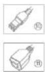
B
-
Reset button
-
Password reset
-
Status LED for 12 V power supply
-
Lens
-
Photo sensor
-
Fixing screws for camera module
EIR
-
Recess for removing the cover
-
Recess for concealed cable routing
-
Breakout point, if lateral cable
routing is desired
-
12 V power supply
-
RI45 connection, PoE capable
FR
text_image
Technical diagram of an Airbus AG motor with numbered components and labeled parts
text_image
Technical diagram of a mechanical device with numbered components and exploded view labelsDH
- lens
- Photo sensor
- Status LED
- IR LEDs
- Base plate
- Safety screws
- Sun shield
FR
- Breakout point, if lateral cable routing is desired
- 3-axle mount
- Password reset
- Reset button
- Alarm input and output
- Power supply 12 VDC
- RI45 connection, PoE capable
PR
①
text_image
Technical diagram of a mechanical device with numbered components and labeled parts in Chinese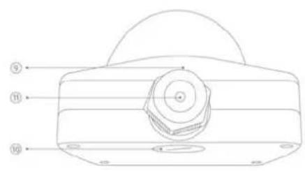
text_image
Technical diagram of a mechanical component with numbered parts labeled 9, 10, and 11

DE
- Reset button
- Password reset
- Status LED for 12 V power supply
- Lens
- Photo sensor
- Fixing screws for camera module
F8
- 12 V power supply
- RJ45 connection, PoE capable
- Recess for removing the cover
- Recess for concealed cable routing
- PG screw connection M25 for lateral cable routing
FR
text_image
Technical diagram of a mechanical device with numbered components and labeled parts
text_image
Technical diagram of a mechanical device with numbered components and exploded view indicatorsUR
- Lens
- Photo sensor
- Microphone
- IR LEDs
- Base plate
- Safety screws
- Alarm input and output
- Power supply 12V
- RJ45 connection, PoE capable
FR
[Non-Text]
[Non-Text]
[Non-Text]
[Non-Text]
[Non-Text]
[Non-Text]
[Non-Text]
[Non-Text]
[Non-Text]
FR
- (1)
- [Non-Text]
18.
PL
text_image
Technical diagram of a mechanical device with numbered components for identification
text_image
Technical diagram of a dome-shaped device with numbered components and corresponding close-up images labeled ⑩ and ⑪.DE
- Reset button / Zoom In
- Password reset / Zoom Out
- Status LED for 12 V power supply
- Lens
- Photo sensor
- Fixing screws for camera module
FIR
- Recess for removing the cover
- Recess for concealed cable routing
- Breakout point, if lateral cable routing is desired
- 12 V power supply
- RJ45 connection, PoE capable
FR
- Lens connection
- ¼ inch thread on top
and bottom sides - Status LED
- Lens base (CS mount)
- Photo sensor
FR
- Analogue video output for service
- Status LED for 12 V power supply
- Audio input
- Audio output
- Reset button
- Reset button
- Password reset
- Micro SD card slot
- 12 V power supply
- Alarm input and output
- RI45 connection, PoE capable
- Earth connection
FR
(1) 本次股东大会的召集和召开程序
PL
text_image
Technical diagram of an ABUS industrial sensor with numbered components and labeled parts
text_image
Technical diagram of a mechanical device with numbered parts and corresponding component labels in ChineseDE
- Lens
- Phot
- Status LED
- IR LEDS
- Base plate
- Safety screws
- Sun shield
用
- Breakout point, if lateral cable routing is desired
- 3-axle mount
- Password reset
- Reset button
- Alarm input and output
- Power supply 12 VDC
- RJ45 connection, PoE capable
- Audio Input
- Audio output
- Analogue video output for service
四
⑪
text_image
Technical diagram of a mechanical device with numbered components and directional arrows indicating assembly or flow.
text_image
Technical diagram of a mechanical component with labeled parts and two inset images showing internal components.DE
- Reset button / Zoom In
- Password reset / Zoom Out
- Status LED for 12 V power supply
- Lens
- Photo sensor
- Fixing screws for camera module
图
- 12 V power supply
B. RJ45 connection, PoE capable - Recess for removing the cover
- Recess for concealed cable routing
- PG screw connection M25 for lateral cable routing
m
natural_image
Two green plastic electrical connectors shown from different angles (no text or symbols visible)text_image
TVIP92700 | Outdoor Dome | H.264 1920X1080 ABUS Install Plugin > There is no Browser plugin installed. You should install the TVIP Plugin to view camera video stream. Continue without Plugin > Image display is slower without plugin.
natural_image
Interior view of a computer lab with electronic equipment and a person working at a desk (no visible text or symbols)natural_image
Close-up of a car interior with curved pipes and wiring, no visible text or symbols on the main subject.30, 25, 15, 10, 5, 2
natural_image
Five different ARIS security cameras shown from different angles (no text or labels visible)Версия 09/2016
TVIP91XXX
TVIP92XXX
CE
Уважаемый клиент,
text_image
Technical diagram of a Mitsubishi industrial sensor with numbered components and labeled parts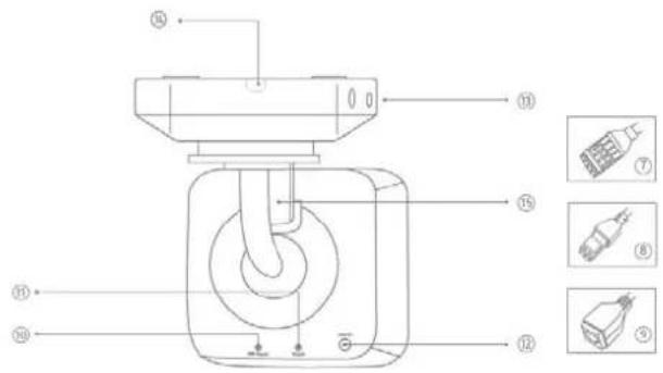
text_image
Technical diagram of a mechanical device with numbered components and exploded view indicatorsDE
- lens
- Photo sensor
- Microphone
- IR LEDs
- Base plate
- Safety screws
①
- Alarm input and output
- Power supply 12V
- RJ45 connection, PoE capable
- Password reset
- Reset button
- Power LED
- Safety screws
- Breakout point, if lateral cable
routing is desired - 3-axle mount
FR
text_image
Technical diagram of a device with numbered components and labeled parts in Chinese
text_image
Technical diagram of a dome-shaped device with numbered labels pointing to its components.
B
-
Reset button
-
Password reset
-
Status LED for 12 V power supply
-
Lens
-
Photo sensor
-
Fixing screws for camera module
EIR
-
Recess for removing the cover
-
Recess for concealed cable routing
-
Breakout point, if lateral cable
routing is desired
-
12 V power supply
-
RI45 connection, PoE capable
FR
text_image
Technical diagram of an ADRUS sensor with numbered components and labeled parts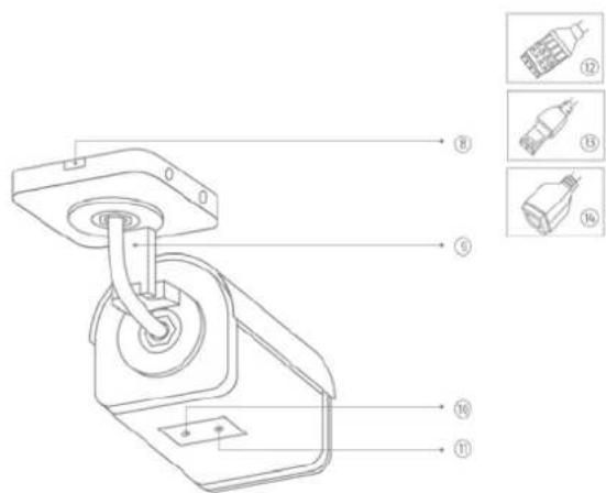
text_image
Technical diagram of a mechanical device with numbered components and exploded view labelsDH
- lens
- Photo sensor
- Status LED
- IR LEDs
- Base plate
- Safety screws
- Sun shield
FR
- Breakout point, if lateral cable routing is desired
- 3-axle mount
- Password reset
- Reset button
- Alarm input and output
- Power supply 12 VDC
- RI45 connection, PoE capable
PR
①
text_image
Technical diagram of a mechanical device with numbered components and labeled parts in Chinese
text_image
Technical diagram of a mechanical component with numbered parts labeled 9, 10, and 11

DE
- Reset button
- Password reset
- Status LED for 12 V power supply
- Lens
- Photo sensor
- Fixing screws for camera module
F8
- 12 V power supply
- RJ45 connection, PoE capable
- Recess for removing the cover
- Recess for concealed cable routing
- PG screw connection M25 for lateral cable routing
FR
text_image
Technical diagram of a mechanical component with numbered parts labeled ① to ⑥
text_image
Technical diagram of a mechanical device with numbered components and exploded view labelsUR
- Lens
- Photo sensor
- Microphone
- IR LEDs
- Base plate
- Safety screws
- Alarm input and output
- Power supply 12V
- RJ45 connection, PoE capable
FR
[Non-Text]
[Non-Text]
[Non-Text]
[Non-Text]
[Non-Text]
[Non-Text]
[Non-Text]
[Non-Text]
[Non-Text]
FR
- (二)
B. - 单位
td.
PL
- (二) 2017年
B. - 10
- 11.
[Non-Text]
[Non-Text]
广力云智慧零售收银系统
。
[Non-Text]
[Non-Text]
[Non-Text]
[Non-Text]
[Non-Text]
[Non-Text]
[Non-Text]
[Non-Text]
[Non-Text]
[Non-Text]
[Non-Text]
[Non-Text]
[Non-Text]
[Non-Text]
[Non-Text]
[Non-Text]
[Non-Text]
[Non-Text]
NL
[Non-Text]
[Non-Text]
[Non-Text]
[Non-Text]
[Non-Text]
[Non-Text]
[Non-Text]
[Non-Text]
[Non-Text]
2
c
[Non-Text]
[Non-Text]
[Non-Text]
[Non-Text]
[Non-Text]
[Non-Text]
[Non-Text]
[Non-Text]
[Non-Text]
[Non-Text]
2
c
[Non-Text]
[Non-Text]
[Non-Text]
[Non-Text]
2
[Non-Text]
[Non-Text]
[Non-Text]
[Non-Text]
[Non-Text]
[Non-Text]
[Non-Text]
[Non-Text]
[Non-Text]
[Non-Text]
341
341
[Non-Text]

text_image
Technical diagram of a mechanical device with numbered components for identification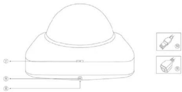
text_image
Technical diagram of a device with numbered components and corresponding close-up images labeled ⑩ and ⑪.DE
- Reset button / Zoom In
- Password reset / Zoom Out
- Status LED for 12 V power supply
- Lens
- Photo sensor
- Fixing screws for camera module
广
- Recess for removing the cover
- Recess for concealed cable routing
- Breakout point, if lateral cable routing is desired
- 12 V power supply
- RJ45 connection, PoE capable
FR
- Lens connection
- ¼ inch thread on top
and bottom sides - Status LED
- Lens base (CS mount)
- Photo sensor
FR
- Analogue video output for service
- Status LED for 12 V power supply
- Audio input
- Audio output
- Reset button
- Reset button
- Password reset
- Micro SD card slot
- 12 V power supply
- Alarm input and output
- RI45 connection, PoE capable
- Earth connection
PL
text_image
Technical diagram of an ABUS industrial sensor with numbered components and labeled parts
text_image
Technical diagram of a mechanical device with numbered parts and corresponding component labels in ChineseDE
- Lens
- Phot
- Status LED
- IR LEDS
- Base plate
- Safety screws
- Sun shield
用
- Breakout point, if lateral cable routing is desired
- 3-axle mount
- Password reset
- Reset button
- Alarm input and output
- Power supply 12 VDC
- RJ45 connection, PoE capable
- Audio Input
- Audio output
- Analogue video output for service
四
[Non-Text]
⑪
text_image
Technical diagram of a mechanical device with numbered components and directional arrows indicating assembly or flow.
text_image
Technical diagram of a mechanical component with labeled parts and two inset images showing internal components.DE
- Reset button / Zoom In
- Password reset / Zoom Out
- Status LED for 12 V power supply
- Lens
- Photo sensor
- Fixing screws for camera module
图
- 12 V power supply
- R045 connection, PoE capable
- Recess for removing the cover
- Recess for concealed cable routing
- PG screw connection M25 for lateral cable routing
m
natural_image
Two green plastic electrical connectors shown from different angles (no text or symbols visible)text_image
TVIP92700 | Outdoor Dome | H.264 1920X1080 ABUS Install Plugin > There is no Browser plugin installed. You should install the TVIP Plugin to view camera video stream. Continue without Plugin > Image display is slower without plugin.
natural_image
Interior view of a computer lab with electronic equipment and a person at the desk (no visible text or symbols)natural_image
Interior view of a car showing curved pipes and wiring, with no visible text or symbols on the main subject.These operating instructions are published by ABUS Security-Center GmbH & Co.KG, Linker Kreuthweg 5, 86444 Affing, Germany. No reproduction (including translation) is permitted in whole or part e.g. photocopy, microfilming or storage in electronic data processing equipment, without the express written consent of the publisher. The operating instructions reflect the current technical specifications at the time of print. We reserve the right to change the technical or physical specifications.
© Copyright 04/2015 by ABUS Security-Center